VEXILAR FL-10 User manual

1
CONTENTS
General Description 2
Specifications 3
Unit Installation 4 - 5
Transducer Installation 6 - 9
Unit Operation 10 - 15
elpful Tips 16
Trouble Shooting Chart 17
About Transducer Beam Angles 18 - 19
Other Vexilar Products 20 - 21
Transducers 22 - 22
Service and Support 24
Founded in 1960, Vexilar, Inc. has a
long history of bringing revolutionary
technology to the sport fishing industry.
Just some of the Vexilar firsts include: the
first liquid crystal display, the first fish
alarm, the first three color display, and
the first CRT and straight line paper
graphs for the sport fisherman.
FL-10 Operation Manual

2
GENERAL DESCRIPTION
The FL-10 is a
compact in-dash
mounted flasher
fish finder. Besides
indicating depth,
the unit also shows
changes in bottom
content and condi-
tions. It can also
discriminate
between large underwater targets, such as fish, and smaller
targets like baitfish and plankton.
The unit transmits bursts of high frequency pulses, which
are converted from electrical to mechanical energy by the
transducer. These "sound" pulses radiate from the
transducer downward and are reflected back up to the
transducer where the energy is converted back to electrical
signals. The FL-10 then processes these signals and displays
them.
The circular display is accomplished by attaching an LED
(Light Emitting Diode) to a wheel, which is then spun at a
high speed in the clockwise direction. This allows for an
extremely high speed update. The bottom, as well as other
targets, are displayed as red, orange, or green to indicate
strong, medium and weak signals respectively.

3
SPECIFICATIONS
Operating Voltage: 10.5 - 15 Volts (12 Volts Nominal)
Current Draw: .25 Amps
Power Output: 400 Watts (Peak to Peak)
Frequency: 200 k z
Resolution: 525 Segments
Target Separation: 2.65" Min.
Display Colors: 3 - Red, Orange, and Green
Depth Scales: 0-20, 0-40, and 0-200’ Feet
Weight: 2-1/2 Lbs. w/transducer
Tran ducer Beam Angle:
Puck Style - 12 Degree
Transom Mount - 12
Degree
Additional beam angle
options are available.
See page 22
Dimen ion
The FL-10 is designed to
fit in a 3-3/8” to 3 1/2”
hole.

4
UNIT INSTALLATION
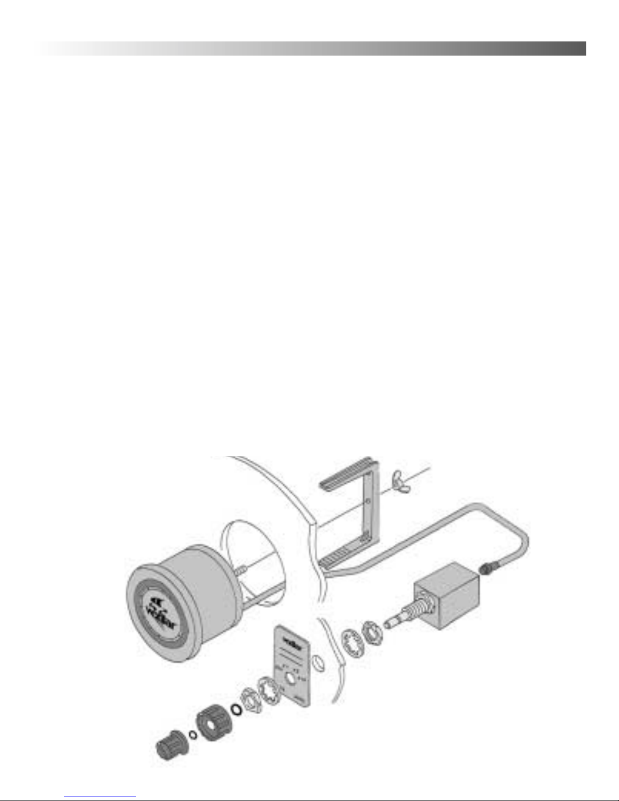
To install the unit refer to Figure 4. You must have a
minimum 3-3/8" hole in your dash or panel. Also, within 12",
you should dedicate space for a 3/8" hole for the control and
decal. Make sure that you will have enough room behind the
dash to accept the unit and control. The flasher unit and the
control each needs at least 3" of depth.
To mount the flasher unit, feed the transducer, power, and
control cables through the larger hole and set the unit into
place. From behind the panel, place the metal U bracket onto
the back of the unit so that the arms of the bracket will make
contact with a solid part of the backside of the panel. Make
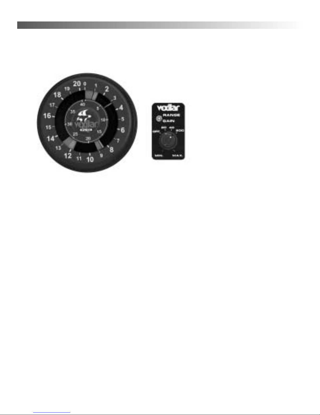
sure the Zero Mark on the flasher display is at the 12 o’clock
position and then use the provided wing nut to tighten the
unit into place. If the stud protruding from the back of the
flasher is not long enough you can reduce the length of the
bracket arms using the marks to guide you. Use a pair of
pliers to snap off a section of each arm at the pre-cut
perforations.
Before you mount the control unit, first install the control
decal. Remove the peel-off backing and carefully place the
decal over the hole making sure that the hole in the decal
aligns with the hole in the dash and that the decal is straight
and level before you press it into place. Next, install a nut,
star washer onto the control shaft. Insert the control unit from
behind the panel into the 3/8" hole. Install the remaining nut
and star washer onto the shaft from the front side. The posi-
tion of the nuts will be determined by the thickness of the

panel. Ideally you want the outside nut to be as close to the
outer end of the shaft as possible. When the right spacing has
been achieved tighten snugly into place.
Make sure the inner shaft portion is rotated fully
counter-clockwise and then place the larger rubber o-ring fol-
lowed by the larger control knob onto the shaft. Using the
provided wrench, tighten the knob down. Make sure that the
white mark lines up with the OFF position on the decal. Next
install small rubber o-ring and then the smaller control knob.
Make sure that, with the shaft turned fully counter-clock-
wise, the white mark lines up with the minimum position.
Finally, plug the eight pin connector from the flasher unit into
the back of the control and tighten snugly.
Connect the power cable to a 12 volt source. It is
recommended to use the main starting battery for power.
Connect the white wire to positive and the black to negative.
5
Figure 4

6
PUCK TRANSDUCER MOUNTING
To attach a puck style transducer
to a trolling motor use the large cable
tie provided. Notice the slots in the
transducer for this purpose. Locate the
transducer on the bottom of the lower
unit (figure 5). Run the cable up the
shaft using smaller cable ties to hold
it in position. Make sure that the
motions of the trolling motor will not
damage the cable. Before you plug the
transducer connector into the inline
jack, it is recommended to spray some
lubricant or dab some common petroleum jelly inside. This
will help prevent long term corrosion.
IN-HULL MOUNTING
Puck transducers can also be mounted in-hull. This
method gives high-speed readings without the worry of
having a transducer hanging on the back of the boat to get
damaged. Finding the best location for the transducer before
installation is critical. Choose a flat smooth spot near the
center of the transom of the boat near the drain plug area. It
is recommended to make a "test run" before you permanently
install the transducer to make sure that you can get a good
reading through your hull at all speeds. You may need
someone’s help for the test, but it will insure you get a good
reading after final installation.
Figure 5

7
After the boat is launched, put about a half inch of water
in the bilge and set the transducer into the the water. Moving
it even an inch in any direction can effect the quality of the
reading drastically. Move it around until you get the best
reading. Be sure to try this when the boat is on plane and
running at top speed. Mark the best spot.
To install the transducer, first clean the spot of mud and
oil and then dry it thoroughly. Using an epoxy* or silicone
glue, make a puddle, about the same size as the transducer,
on the inside of the hull. Place the transducer in the glue and
press it down firmly, gently twisting it back and forth,
making sure that there are no air bubbles in the glue between
the transducer and the hull. It is important that you let the
glue dry completely before turning the unit on.
Run the transducer cord up to the unit. Before you plug
the transducer connector into the inline jack, it is
recommended to spray some lubricant or dab some common
petroleum jelly inside. This will help prevent long term
corrosion.
* If your hull is aluminum, use silicone. This material will flex with
the hull at high speeds and in rough water.

8
TRANSOM TRANSDUCER MOUNTING
Locate the transducer, and bracket hardware. This
includes;
1 - Transducer
2 - Angle Brackets
4 - Bracket Screws
2 - Bracket Plates
4 - Nuts
4 - Mounting Screws
First, attach the bracket to the transducer as shown in
Figure 7. The flanges of the bracket normally point outward,
away from the transducer. If mounting space is tight, you can
reverse the angle brackets and face the flanges inward.
TRANSOM TRANSDUCER INSTALLATION
When choosing an area to mount the transducer, keep in
mind that you need smooth water flow across the face of the
transducer to insure a good reading at all speeds. Try to stay
away from rivets, ribs, or strakes that would be just in front
of the transducer. They can disturb the water and scramble
the reading.
With the mounting bracket attached to the transducer,
hold it up to the boat where you are planning to mount it.
Mark the holes on the transom, or mounting plate, so the
bottom of the transducer is flush with the bottom of the boat
the holes are located at the bottom of the bracket slots. This
gives you room to "fine tune" the position of the transducer
and optimize your reading after you've put the boat in the

9
water. Ideally, the
transducer should be just
under the bottom of the
boat. owever, you may
need to lower it 1/2” to
5/8”, depending on your
hull shape, to get a good
reading at top speed.
Drill out the holes and
tighten the bracket to the
hull securely. Be sure to
seal any holes drilled into
the transom with silicone
to prevent water from
leaking into the boat. Give
the rear of the transducer
a slight tilt downward so
that the back is about 1/8”
lower than the front.
Tighten the bracket screws and nuts securely. Run the trans-
ducer cord up to the unit. Before you plug the transducer
connector into the inline jack, it is recommended to spray
some lubricant or dab some common petroleum jelly inside.
This will help prevent long term corrosion.
Figure 7

10
UNIT OPERATION
To switch the FL-10 on, turn the larger control knob to the
right. Turning the unit on also selects the depth range. The
first setting covers zero to 20 feet. The second range covers 0
to 40 feet and the third range covers 0 to 200 feet. If the first
setting shows only a mark at the zero position on the display,
switch to a deeper range until you see the depth mark appear.
Depth is read in the clockwise direction. Zero, or the water
surface, is at the 12:00 position. The depth gets deeper as you
go around the dial clockwise.
GAIN CONTROL
The smaller knob is the gain control. This controls the
amount of signal that you see on the display. A gain setting
of MIN will display a minimum amount of signal while a
gain setting of MAX will show the maximum amount.
Different conditions will require different gain settings. Deeper
water will require higher gain than shallow water. A weedy
bottom will demand a lower gain setting than a clean bot-
tom. Keep the gain level low. Too much gain can "wash out"
the targets that you want to see. Generally, it is a good idea
to set the gain at an appropriate level and leave it there, unless
water depth or conditions change substantially.

11
HOW TO FIND BOTTOM
To read how deep it is, start at the zero mark (at the 12
o’clock position) and move clockwise. The bottom will be the
largest mark other than the zero. The leading edge, the one
closest to zero, will be where you read the depth. The width
and color makeup of the bottom mark tells you what kind of
bottom it is.
The three-color display on the FL-10 will give you a lot
more information than just depth. A color represents the
strength of a signal. A red color indicates a strong signal, an
orange color indicated a medium strength signal, and green
represents a weak signal. The colors will combine to give you
information about objects, such as bottom echoes, structure,
fish, and plankton. The way in which these colors combine,
and the width of the marks, tells you what is what.
Note - Depth will not “wrap” beyond zero. Changing ranges is
required if the depth drops below the current range setting.
HARD BOTTOM
Under these conditions the bottom will be mostly red,
although you will always see some orange and green at the
trailing edge, as in figure J. A sharp red leading edge tells you
that the bottom is very clean. If you were to move from a hard
bottom to a softer bottom you would see the bottom mark
get wider and a change in color to more orange and green.
Try not to change the gain setting as you move around as this
will affect the color and width of the mark.

12
Figure. J
Figure. K
ZERO MARK
ZERO MARK
TRAILING
EDGE
TRAILING
EDGE
BOTTOM
SIGNAL
BOTTOM
SIGNAL
SURFACE
CLUTTER
SURFACE
CLUTTER
BAIT FIS
OR
PLANKTON
FIS
LEADING EDGE
Read Depth Here
LEADING EDGE
Read Depth Here
POSSIBLE FIS
WEED TOPS
WEEDS

13
WEEDY BOTTOM
In weedy conditions the bottom can be harder to
determine. Figure K gives you an idea of what it may look
like. To find the bottom in weeds it is important to keep the
gain control low. If the gain is too high the bottom and the
weeds will "run together" making it difficult to determine the
actual depth. Some weed beds can be so dense that they will
display as solid color, even at minimum gain. To find depth
in these conditions it is often helpful to read the display
backwards. In the counter-clockwise direction, look for the
bottom by first finding the trailing edge of the signal. Further
into it, you’ll see the main part of the bottom mark and then
the leading edge , as in figure K. If you are in weedy
conditions often, you may want to add an S-Cable to your
system (see page 23). This cuts down your output power
allowing for clearer readings in shallow weedy water.
SEEING FISH
The FL-10 sees a fish as a target, much like the bottom. It
has a leading edge, a width, and color content. Refer again
to figure J. If the range control is set to the 20 foot scale, then
the fish is just over three feet above the bottom. It is a fairly
wide mark and is made up of all three colors. This should be
recognized as a significant fish, something you may want to
catch. The marks that appear just above this fish are smaller
and there is no red. ere is where target identification gets a
bit trickier. Since we do not know the position of the targets

14
in the cone of sound we cannot readily identify them. For
example, the green mark at seven feet in figure J could be a
small piece of floating debris or a single small baitfish in the
center of the cone. It could also be a large game fish at the
very edge of the transducer cone.
In the weeds, spotting fish is more difficult. Figure K
shows a bottom at twelve feet. The weeds extend from the
bottom up to about six feet. Notice the red mark at nine feet
is labeled "possible fish". We cannot say that it is a definite
fish because the weeds around it are dense enough to give a
red signal themselves. Again, keep the gain as low as you can
for reading in the weeds. If you can't turn the gain down far
enough you may want to get an optional S-Cable to cut down
the power of your unit.
CLUTTER AND NOISE
Clutter is created by very small targets in the water. It is
usually displayed as thin green or orange lines. Clutter can
include bait fish, plankton, floating debris, or air bubbles.
Although clutter is not fish, it can be useful in finding fish.
One type of noise is electrical noise, which is caused by
the engine ignition, radios, or trolling motors. It can be
displayed as red, orange, or green marks that flash as the
interfering equipment is operated. The FL-10’s internal
circuitry will block out most noise, but sometimes, extra
measures are required to eliminate it. Please contact our
service department or log on to www.vexilar.com for more
information.

15
Another type of noise is acoustical. This comes from the
transducer picking up noise from turbulent water under the
transducer. This can be due to a poor transducer mounting
job or from engine exhaust or trolling motor thrust passing
under it. Acoustical noise can be eliminated by adjusting the
transducer’s location or position.
HIGH SPEED OPERATION
The FL-10 can accurately read depths at almost any boat
speed. ere high speed is defined as any speed at or above
the planning speed of the boat. Once the boat starts to plane
out, turbulence will develop behind the transom. If you are
using the wrong type of transducer, or it is poorly mounted,
the unit will lose the bottom at a certain boat speed or fill the
display with acoustical noise. This is due to all of the air
bubbles in the turbulent water. Make sure you are using the
proper transducer for your application and that you follow
the mounting instructions carefully.
NAVIGATION
Although the FL-10 can give you a very fast update of
depth information, use common sense when navigating. Even
though you can see the depth get shallow fast, you may not
be able to react fast enough to avoid danger. Plea e navigate
with extreme caution.

16
HELPFUL TIPS
WHERE TO SET THE GAIN CONTROL
Set the gain control so as to get a strong bottom mark. If
you don’t see a bottom mark, switch to a deeper range
setting, then turn the gain up until the bottom appears. Good
bottom marks will show all three colors. The leading edge of
the bottom echo should show a solid red band bleeding into
orange. The trailing edge of the bottom mark will bleed from
orange into green. Keep the gain control as low as possible,
especially in weedy conditions, while still showing a good
bottom signal.
HOW TO RECOGNIZE FISH
Any mark that is between the zero and the bottom marks,
but not connected to either, COULD be a fish. Remember that
the colors indicate the strength of the mark. If you see a red
mark, it probably is a fish. The wider the red part of the mark
is, the larger the fish is. An orange or green mark could also
be fish, but we do not know for sure. They may indicate small
bait fish or larger fish off to side of your position. Only if these
marks turn to red can you be fairly sure it is a fish.
AVOIDING TROLLING MOTOR NOISE
Usually a simple grounding wire connected between the
negative trolling motor lead and the negative starting
battery post will eliminate any noise. Use an 18 gauge wire
with a 1 amp fuse. Contact Vexilar service or log on to
www.vexilar.com for more information.

17
TROUBLE SHOOTING CHART
Symptom Possible Cause
Unit is turned on, but no
display and motor is not
running.
Check for bad connections, proper hook
up polarity, and make sure you have a
good, fully charged, battery.
Unit is turned on and
the motor is running,
but there is no display.
Supply voltage too low. The unit will
show no display if the voltage is below
10 volts. Check while unit is running.
Unit runs well for a
short time, then lights
fade out or unit quits.
Low battery or bad connection. Voltage
may be good when checked, but will fall
as unit runs.
Unit runs and shows
display light, but does
not read depth.
Transducer is not plugged in, not in con-
tact with the water. Unit needs to be set
to a deeper range or higher gain.
Unit works, but needs
high gain to see bottom
or targets.
Transducer is not aimed correctly or
needs to be cleaned. In-hull mount may
be loose. Remove S-Cable
Unit works, but has too
many lines on the dis-
play. Can't tell what is
what.
Improper transducer mounting. Also,
gain may be set too high or ,if gain is set
to minimum, you may need an S-Cable
(see page 23).
Unit works well when sit-
ting still or when slow
trolling, but loses reading
at higher speeds.
Improper transducer style, installation,
or adjustment causing a loss of smooth
water flow under the transducer when
the boat reaches a certain speed.
Unit shows noise when
engine or electric motor
is turned on.
Defective engine or electric motor. Also
can be improper wiring or missing
ground in electrical system.
Everything is working
great, but cannot catch
any fish.
That is why they call it “fishing” and not
“catching”. We here at Vexilar experience
this often. --- Just have fun.

18
ABOUT TRANSDUCER BEAM ANGLES
Beam angle has a large effect on the performance of your
depth finder. There is more to it than simply area of cover-
age. The correct beam angle to use depends entirely on what
you are trying to do with your sonar. If you are fishing for
suspended fish then you probably would be very pleased
with the performance of a 19º. owever, if you were going
after fish that are hanging right on the bottom, along a steep
drop-off in very deep water, you would have better results
with a 9º. ere's why;
Dead Zone is an area within the transducer’s cone of
sound that is blind to you. The wider the beam angle the
greater the possible dead zone. The sonar will mark bottom
as the nearest distance it sees. If you are fishing over a slope,
it may see the high side of the slope, at the edge of the cone,
and mark that as bottom. The fish that are hanging on the
bottom in the center of the cone will
be invisible to you because they are
actually within the bottom signal on
your depth finder. A narrower beam
angle will reduce this effect.
A depth finder puts out a constant
amount of power. It does not matter
where you have the gain level set.
Gain simply controls how much you
amplify the signal that is bounced off
of the bottom. Therefore, a narrow
beam transducer will appear to be

19
Depth 9º 12º 19º
10’ 1.6’ 2.2’ 3.4’
20’ 3.2’ 4.3’ 6.7’
30’ 4.7’ 6.3’ 10.0’
40’ 6.3’ 8.4’ 13.4’
50’ 7.9’ 10.6’ 16.7’
60’ 9.4’ 12.6’ 20.8’
70’ 11.0’ 14.7’ 23.4’
80’ 12.6’ 16.8’ 26.8’
90’ 14.2’ 20.0’ 30.1’
100’ 15.7’ 21.0’ 33.5’
120’ 18.9’ 25.2’ 40.2’
150’ 23.6’ 31.5’ 50.2’
200’ 31.4’ 42.0’ 67.0’
This chart indicates the transducer’s theoretical beam angle. What
you actually see on the display of your depth finder depends on factors
such as target size, reflectivity, and gain level.
much more powerful than a wide beam transducer. This is
because you are putting that same amount of power into a
smaller area. This can be an advantage if you are fishing in
deep water or a detriment if you are fishing shallow. A nar-
row beam transducer can be overpowering in shallow water.
The FL-10 In-Dash comes standard with the 12 degree
angle. This beam angle that works well in most applications.
You can purchase optional transducers, for more specialized
applications, with different beam angles.
Actual shape
of beam
Theoretical
Beam Angle
(-3dB Point)
Tran ducer Area of Coverage v Depth

20
More Depth Finder From Vexilar
The EDGE2Model LC-507
The Edge, LC-507, is an amazing depth
sounder. It is unique in that it is like
having two totally different sonar
systems in one unit. It comes with two
transducers, a 107 k z, 38 degree, and a
400 k z, 10 degree. The idea is that you mount the
transducers right next to each other and compare the two
different views directly on the split screen. You can also run
either beam at full screen. Speed, temp, and voltage sensors
are included. This unit was designed for the very serious
fisherman, but is one of the easiest units ever made to
understand and operate.
The FL-18
The FL-18 is the first ever flasher to
incorporate a split-screen zoom. With two
modes of zoom, a low power mode for
shallow water, and a super bright display,
this unit is the ultimate three-color flasher.
The FL-8SE
The FL-8SE has the same great features
as your FL-10 In-Dash, plus six depth
ranges and an enhanced interference
rejection system that allows it to run
cleanly right next to another depth finder.
Other manuals for FL-10
1
Table of contents
Other VEXILAR Fish Finder manuals
Popular Fish Finder manuals by other brands

Humminbird
Humminbird 778c HD XD Operation manual

NorthStar
NorthStar EXPLORER 443D Installation and operation manual

Marcum Technologies
Marcum Technologies Showdown user manual

Navman
Navman TRACKFISH 6500 Installation and operation manual

Apelco
Apelco XVA-70 instruction manual

Raymarine
Raymarine Dragonfly-4 DV Installation and operation instructions