VEXILAR FL Series User manual

1
Vexilar Two-Year Extended
Limited Warranty Application
Price: $39.95 USD
Anytime within 12 months of purchase.
Model Units Covered
FL-8®SE • FLX-12 • FL-18 • FLX-20 • FLX-28
If you purchased a new Vexilar pack that includes a qualifying model, you may buy the
extended warranty, for that head unit only, from Vexilar, Inc. for up to 12 months after
your purchase. This warranty is transferable to a new owner.
Two Ways to Order
By Mail
Send the form below, along with the
standard warranty registration card
attached, along with $39.95. We accept
checks, money order, Visa and MasterCard.
Make checks payable to “Vexilar, Inc.”
Please submit required items to:
Vexilar, Inc.
Attn: Warranty Dept.
6667 West Old Shakopee Rd. Suite 101
Minneapolis, MN 55438
On-Line
Save the stamp and the mailing hassles.
Just go online to complete your standard
warranty registration and complete the
extended warranty form on our website.
http://vexilar.com/warranty
(Required)
Notice: The model and serial number of your unit MUST be provided to Vexilar with your original purchase
date to be able to register your unit for your first two year warranty AND to be able to
purchase the additional two year extended warranty. Batteries warranties are pro-rated. See Page 43
Flasher-Family-Manual-2019.indd 1 5/15/19 12:26 PM

2 3
VEXILAR FL SERIES SONAR/FISH FINDERS
OWNERS MANUAL
For Models:
FL-8®SE | FLX-12 | FL-18 | FLX-20 | FLX-28
Contents
Vexilar — Pioneers
in Marine Electronics 4
About Flashers 5
Flasher Operation
Basic Use 6
About the Display 7
Range Control
FL-8®SE 8
FL-18 9
FLX-12 10
FLX-20 11
FLX-28 12
Setting the Gain 13
Interference Rejection 14
Low Power Mode 16
Auto Zoom 17
FLX-20 Color & Demo Modes 17
Bottom Lock 18
Low Battery Indicator 18
Understanding Zoom
FL-18 Zoom 19
FLX-20 Zoom 20
FLX-28 Zoom 21
Welcome to the FLX-28
FLX-28 Auto Range 22
Multi-Layer Display 24
Color Mode Operation 25
Interference Rejection 26
Mode Settings 27
Battery Voltage 29
FLX-28 FAQs 30
Ice Fishing
Basic Principals 31
The Ice-Ducer™ System 32
Seeing Your Lure 33
Ice Fishing Systems
Genz Pack 34
Pro Pack II 36
Ultra Pack 38
Digital Depth & Battery Level 40
Battery Charging 41
Battery & Charging Tips 42
Pro-Rated Warranty 43
Boat Use
Navigation 44
Bottom Content 45
Vegetation 45
Boat Installation
Unit Installation 46
Power Connection 46
Transducer Installation
Types and Methods 47
Transom Mounting 48
In-Hull Mounting 49
Trolling Motor Mounting 50
Open Water Options 51
About Transducers
Cone of Sound 52
Dead Zone 53
Output Power 53
Parts and Accessories
Accessories 54
Transducers & Replacement Parts 56
Trouble Shooting 58
Electrical Interference 59
Service and Support 60
Product Specifications 61
MNL017U RV2019
Vexilar Two-Year Extended Limited Warranty
The Vexilar extended Warranty is not only the best in the Marine Industry, but also an exceptional
value. Your new Vexilar has a full two-year limited warranty against defects or malfunctions in
material, workmanship, or against failure to conform to the product’s written specifications. (See
specifics in this Vexilar owner’s manual.)
Now you have the opportunity to extend the warranty protection of your Vexilar unit from the time
of purchase by an additional two years—for a total of FOUR YEARS of protection. Models FL-8®SE,
FLX-12, FL-18, FLX-20 & FLX-28 are eligible for this program. This Two-year Extended Warranty must
be purchased within twelve (12) months from the original date of purchase for $39.95. (Please
note, your two years of extended Limited Warranty coverage will take effect after the original
factory warranty expires. This will give you a total of four years of limited coverage based on the
original purchase date of the unit.)
How To Apply
If you decide to participate in the extended warranty program anytime within twelve (12) months
after the original purchase date of the unit, you must buy it directly from Vexilar, Inc. for $39.95. To
qualify, follow the instructions on the previous page.
When mailing your registration, please fill out the information on the extended warranty applica-
tion completely. The serial number of the unit is located on the back of the head assembly. Vexilar
will send you a notice via mail confirming your extended warranty is valid and activated within 6
to 8 weeks. The reply from Vexilar will clearly state when your extended warranty period expires.
If you do not get a confirmation notice within this time, please contact Vexilar customer service im-
mediately as no extended warranty service on your unit will be done if you did not apply properly.
Be sure to keep copies of all receipts for your own records. For more information or for addi-
tional copies of the Vexilar Limited Extended Warranty forms call: 952-884-5291, e-mail
warranty@vexilar.com or visit our website. See order form for complete listing of the select models
covered. Vexilar, Inc. may find it necessary to change or modify this offer at any time.
Extended Warranty Coverage
The Extended Warranty gives you two extra years on the “head” assembly for model FL-8®SE, FLX-
12, FL-18, FLX-20 and FLX-28 units. During the extended warranty period, Vexilar, Inc. will repair
or at its option, replace any parts, labor and return shipping at no cost to you. Your FL unit’s serial
number must be on file with Vexilar in order to receive warranty coverage. The unit must be shipped
prepaid to...
Vexilar, Inc. Attn: Service
6667 West Old Shakopee Road, Suite 101 Minneapolis, MN 55438
This warranty does not apply if the product has been damaged by accident, misuse, internal water
damage or as a result of service modification by anyone other than the factory. This extended
warranty does not cover batteries, chargers, cases, accessories, transducers, gimbal bracket or lost
parts. This warranty is transferable to new owners.
Flasher-Family-Manual-2019.indd 2-3 5/15/19 12:26 PM

4 5
VEXILAR — PIONEERS IN
MARINE ELECTRONICS
Established in 1960, Vexilar, Inc. has been a leading innovator of marine electronics
in the sport fishing industry for over 50 years. Some of their innovations include:
• The first straight-line paper graph for sportfishing (model 155)
• The first CRT (television) display (model 660)
• The first color display (model DE-12)
• The first fish alarm (model 120-SOS)
• The first Liquid Crystal Display (LCD) (model 480)
• The first self-leveling ice fishing transducer design (Ice-Ducer)
• The first split-screen zoom flasher (model FL-18)
• The first shoot-through-aluminum transducer design (AlumaDucer)
• The first 10’ Range Flasher (FL-22HD)
• The first tri-beam transducer in one housing.
• The first WiFi sonar driven by mobile app (SonarPhone)
• The first aftermarket digital Depth Display technology for all flashers (DD-100)
• The first flasher to use Brushless Data transfer technology (FLX-28)
The FL series three-color flashers continue to lead the way in real-time high definition flasher
performance. Quality products backed by world leading customer service are the
bedrock of Vexilar, Inc.
A Long History of Vexilar Products
ABOUT FLASHERS
How Sonar Works
SONAR stands for SOund NAvigation and Ranging. Sound travels through fresh water at
a speed of approximately 4920 feet per second. A sonar device (depth finder/fish finder)
measures the amount of time a burst of energy takes to travel to the bottom and return to
the transducer. This time variation is then displayed on the readout of your sonar. When the
depth gets deeper, the time of travel for the sound increases. The burst of energy, known
as the transmit pulse, is generated by the sonar’s transmit circuitry. This burst is delivered
to the water via the transducer. The return signal, known as the echo, is received by the
receiver circuit, also via the transducer. A central processing unit makes the calculations to
determine the depth and signal strength of the
bottom and other targets.
The sonar signal sent from the transducer will
reflect, or bounce off of any object that has
a different density than water. This makes it
possible to detect not only the lake bottom,
but also vegetation and fish.
How Flashers Work
The sonar portion of a flasher works in the
same manner as any other graph or LCD sonar device. The
difference is in how the return signal is displayed. Instead
of adding the data to a progressive representation of the
bottom to construct a history, the data on the flasher display
always represents the current point in time, also known as
“real time”. The display consists of a wheel with indicator
lights mounted in one location. The wheel is spun at high
speed and the lights turn on and off rapidly to show the
sonar readings.
The Vexilar Advantage
Vexilar’s sonar design offers an optimal balance between the power of the transmitted
pulse and the sensitivity of the receiver circuit. Excessive power has been shown to cause
premature transducer failure, distortion of the sonar signal, and possibly “spook” fish from
the audible noise they hear. Vexilar provides a balanced performance level for a wide
range of fishing scenarios.
Flasher Wheel Stationary
Flasher Wheel Spinning
Lights turn
on and off
rapidly as
wheel is
spun
Flasher-Family-Manual-2019.indd 4-5 5/15/19 12:26 PM

6 7
FLASHER OPERATION
Basic Use
The Vexilar FL series color flashers are great tools for open water and ice fishing. Once
you learn to understand the color display, you can apply this knowledge to greatly
increase your awareness of what’s under the water.
FL SerieS FL a Sh erS Can BeUSed For:
• Determining the current depth at any boat speed.
• Locating fish-holding underwater structure.
• Determining the bottom hardness and transition lines.
• Penetrating thick vegetation to see what’s below.
• Finding fish and the bait they feed on.
• Watching your bait and the fish around it.
Operation of each of the flasher models is very straight forward. You simply turn the unit
on, select an appropriate depth range setting, and then an appropriate gain level setting.
You should change the range and gain settings only when the conditions change.
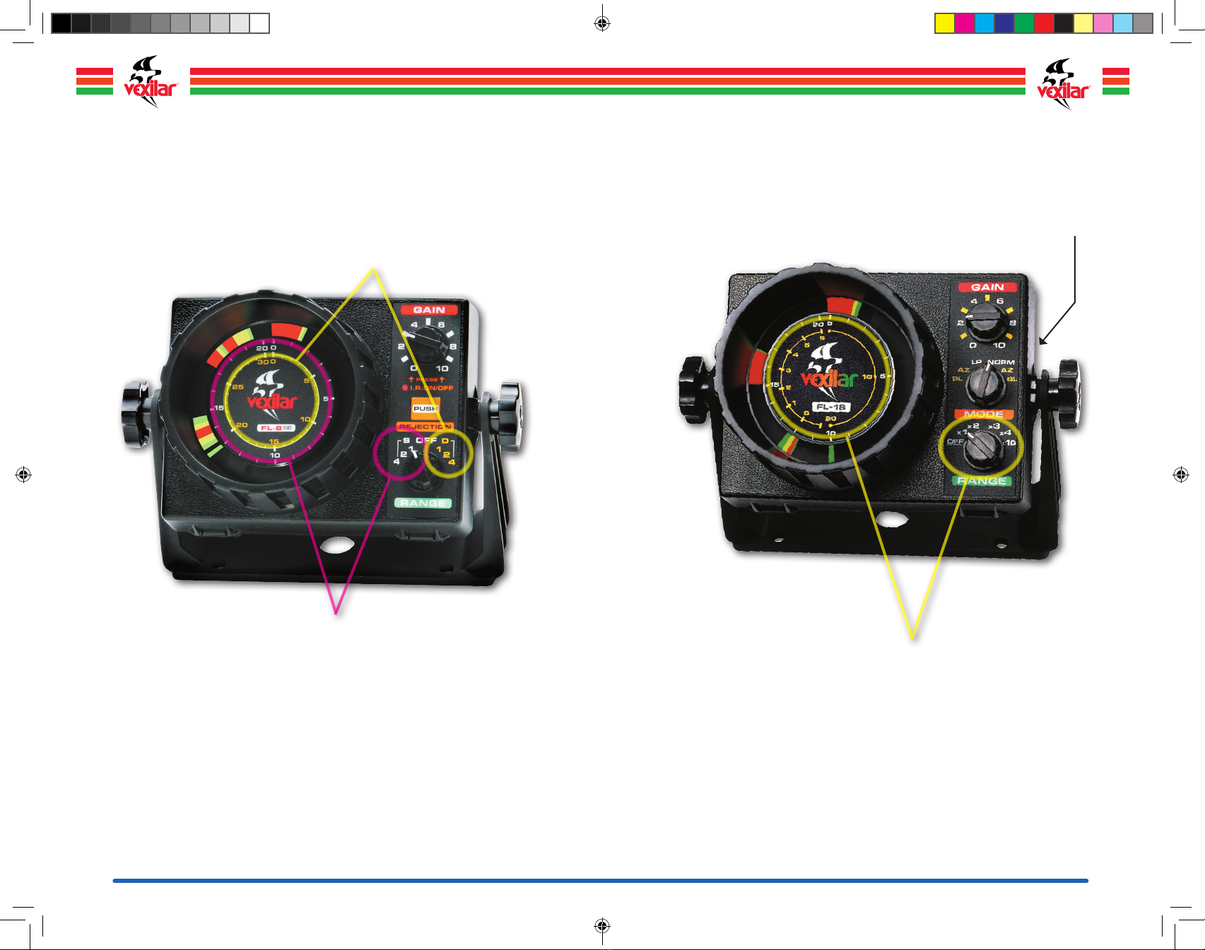
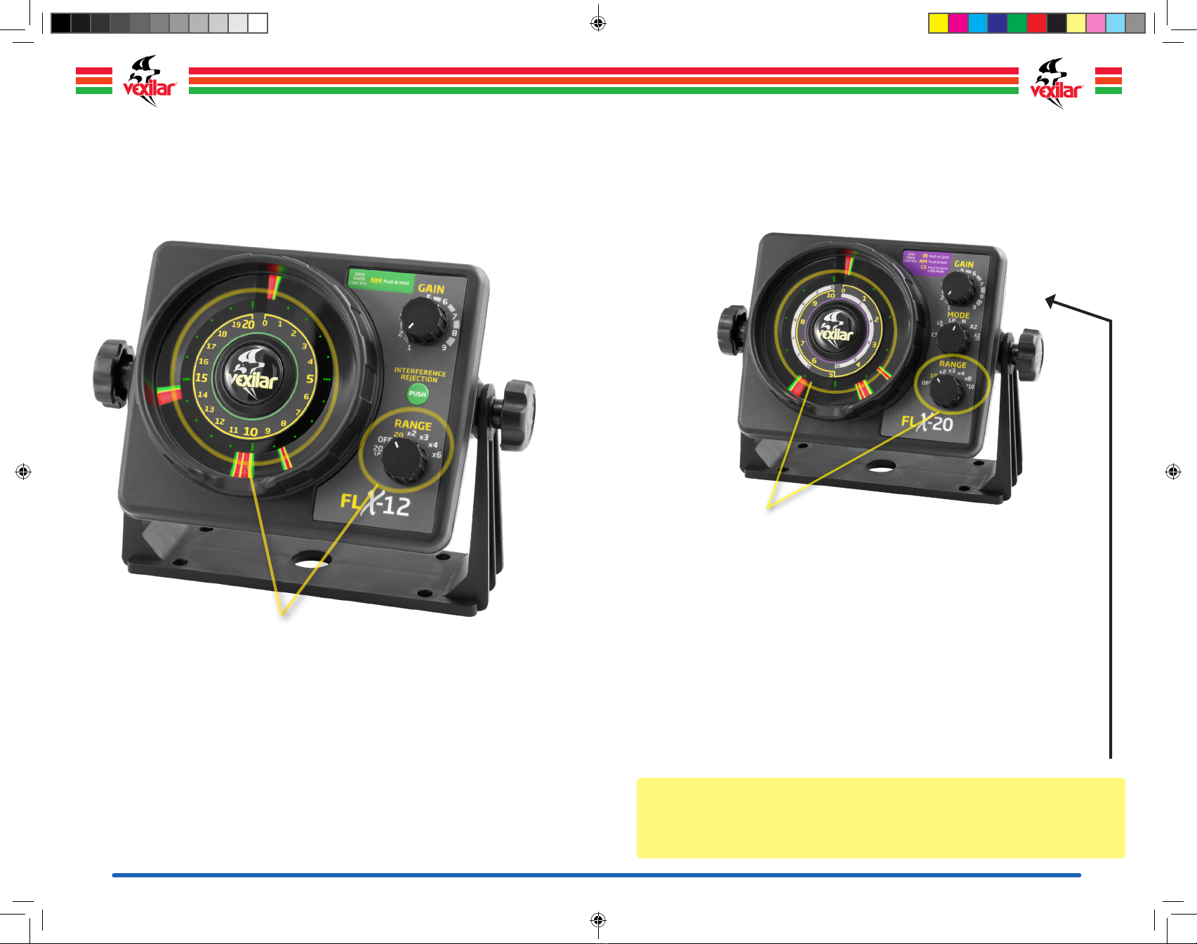
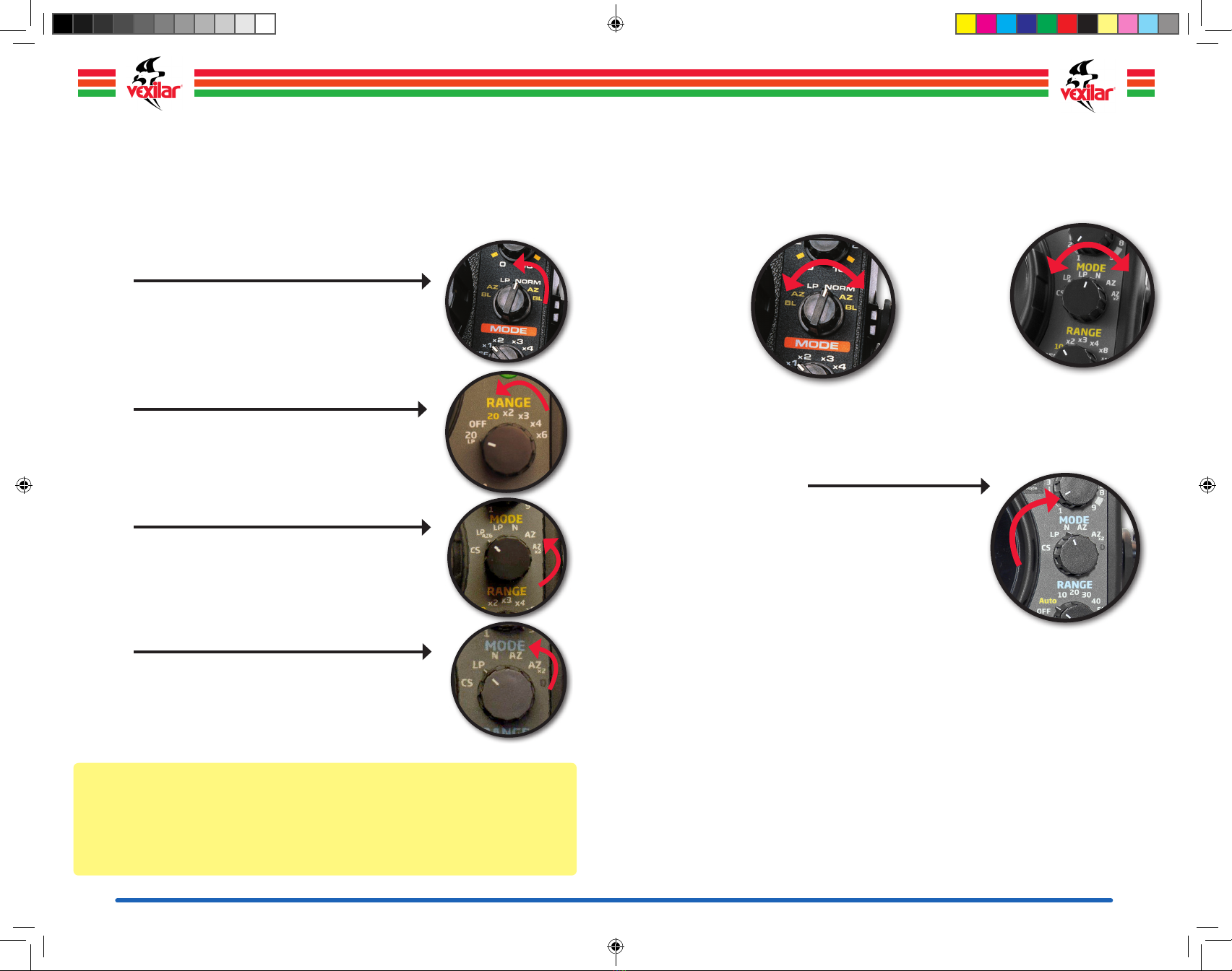
RANGE
Range determines the maximum depth of water in which the flasher can see the bottom.
For example, the shallowest range available on the FL-18 is 0 to 20 feet. This means that if
the water depth is between zero and 20 feet, the bottom will be displayed on the screen.
If the water depth gets deeper than 20 feet, you’ll want to select a deeper depth range
in order to see the bottom.
NOTE: It is usually best to select the shallowest depth range possible to see the bottom.
This allows the water column below to be represented by the greatest amount of display
screen area. This offers the highest resolution, makes things bigger and easier to see.
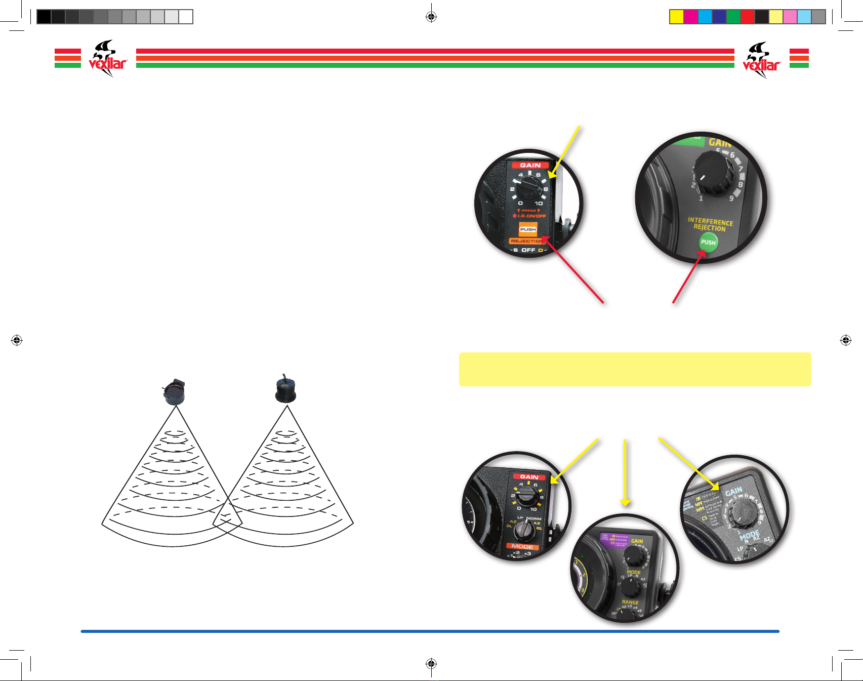
GAIN
Gain controls the amount of amplification applied to the return sonar signal. Think of gain
as your volume control. You turn up the gain to see more of what’s below. You turn down
the gain to see less of what you don’t want to see. The goal is to find a gain level that
shows you as much real information as possible, without displaying stray signals of clutter
and interference. Keep the gain setting as low as possible for best overall performance.
INTERFERENCE REJECTION
This feature rejects sonar interference generated by other nearby depth sounders.
Interference Rejection, or IR, comes on automatically when you turn the flasher on, but
you can adjust the setting if desired. Each unit uses a slightly different control for IR.
About the Display
The FL & FLX series flasher displays consists of multiple colors (marks) which appear at
various positions on the screen. Understanding what the colors mean, and the position
and size of the colored marks, is the key to being able to interpret the information correctly.
RED = Strong Strength Signals. Strong signals are generally produced by
significant underwater objects, such as the bottom, heavy vegetation, and large fish.
However, smaller objects, such as bait fish, can display as red if the object is directly
under the transducer.
ORANGE = Medium Strength Signals. Medium signals are produced by
smaller objects and softer bottom types. Also, medium strength signals can be produced
by larger objects in the immediate area around, but not directly under, the transducer.
GREEN = Weak Strength Signals. Weak signals are produced by small
objects, such as light vegetation, bait fish, and even air bubbles or aquatic micro marine
life. Larger objects off to the sides of the transducer can also be displayed as green.
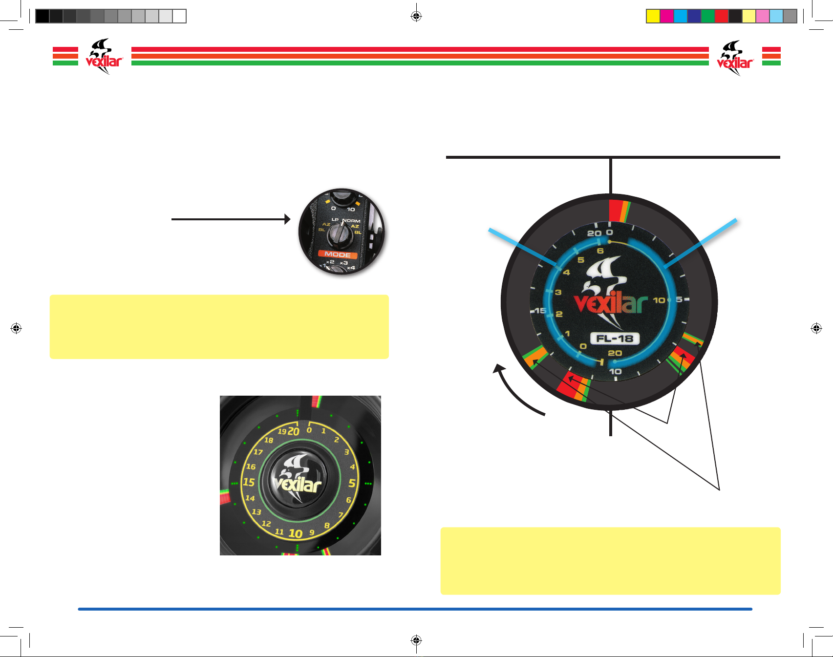
The Zero mark always shows, even if
the transducer is unplugged. This mark
indicates the starting point.
Marks just beyond the Zero
mark can indicate algae,
floating vegetation, or even
“ice noise” caused by thick
ice conditions.
Bottom is generally the
most prominent mark on
the display. Bottom usually
starts with a wide band
of red, with orange and
green trailing. READ DEPTH HERE: The current depth
is indicated by the leading edge of the
bottom mark. The depth is 12 feet here.
You read the display
in the clock-wise
direction. The further
around you go, the
deeper the water.
Fish, bait fish, and even
your lure, will show
anywhere between
the Zero mark and the
Bottom mark. Here,
a weak object shows
about a foot above a
much stronger object.
Marks beyond the bottom
mark can indicate either
hard objects within a soft
bottom or large objects well
off to the side.
What is What?
Here are the basics of what you will see on
the display of an FL series flasher.
NOTE: The FLX-28 has a more sophisticated color scheme. See page 25 for details.
Flasher-Family-Manual-2019.indd 6-7 5/15/19 12:26 PM

8 9
Setting the Range
FL-8®SE
The FL-8®SE has six depth ranges in two groups, Shallow and Deep. The Shallow group
includes Zero to 20’, 40’, and 80’. The deep group includes Zero to 30’, 60’, and 120’.
To interpret depth, you multiply the displayed reading by the range multiplier.
ShaLLow GroUp
• S-1 = Zero to 20 feet. Read the outer white scale directly.
• S-2 = Zero to 40 feet. Read the outer white scale and double the reading.
• S-4 = Zero to 80 feet. Read the outer white scale and multiply by 4.
deep GroUp
• D-1 = Zero to 30 feet. Read the inner yellow scale directly.
• D-2 = Zero to 60 feet. Read the inner yellow scale and double the reading.
• D-4 = Zero to 120 feet. Read the inner yellow scale and multiply by 4.
Setting the Range
FL-18
The FL-18 has 5 depth ranges. Zero to 20’, 40’, 60’, 80’, and 200’. To interpret depth,
you multiply the displayed reading by the range multiplier.
In normal mode, read the outer white scale and multiply by the
range setting. Here, the range is set to “x1”. Bottom is at 15
feet, a fish is at 12 feet, and there is a weak signal at 10 feet.
If the range control was set to “x2”, the bottom would be
interpreted as 30 feet, the fish at 24 feet, and the green mark
at 20 feet.
Normal mode selected
Reading the depth is the same in LP (Low Power) mode. Reading the depth in
AZ (Auto Zoom) or BL (Bottom Lock) mode is discussed on page 19.
Shallow Range Group
Look at the outer scale and the
left-hand multipliers in white
Deep Range Group
Look at the inner scale and the
right-hand multipliers in yellow
Flasher-Family-Manual-2019.indd 8-9 5/15/19 12:26 PM

10 11
Setting the Range
FLX-12
The FLX-12 has a maximum display range of 120 feet, with five depth ranges starting at
the 20 on the 0-20 scale that is marked on the front dial.
As you move deeper to find bottom, you will need to do a little math. The x2 setting
means the dial is now displaying a 0-40 foot scale, the x3 is a 0-60 foot scale the x4
is 0-80 the x6 is 0-120.
The 20’ Low Power (LP) range reads the same as the standard 20 foot range, except
using this selection puts the flasher into Low Power Mode, which is discussed on page
16.
Setting the Range
FLX-20
The FLX-20 has a total of 11 depth ranges to allow you to get maximum display resolution
for the fishing conditions you are in. The primary ranges for the FLX-20 will be in the
normal settings starting with 0-10 feet.
The x2 setting will mean you will need to double the depth on the display so you
now have a 0-20 foot display, the x3 is 0-30, the x4 is 0-40, x8 is 0-80 foot and
x10 will mean a 0-100 foot scale. Now if you want to activate the other set of depth
setting for super deep water fishing to 300 feet you need to follow the following
steps:
Getting into Deep Mode
To activate the 300’ Deep water ranges: Turn gain setting to “1” press in and turn
the unit on at the same time. This essentially triples the standard depth ranges. Now
the display will start out at the 0-30 foot range, the x2 is 0-60, the x3 is 0-90, the
x4 is 0-120, the x8 is 0-240 and the x10 setting is a 0-300 foot display on the dial.
Turning the unit OFF will revert the ranges back to normal.
KNOW YOUR DEPTH! The 0-10 foot scale allows for an easy system to get your depth
reading. If the signal says your bottom is at 6, you then simply look to see where your
range knob is set to and do the simple math. If you are on the x3 setting, then it is 6x3,
or 18 feet it’s that simple!
Flasher-Family-Manual-2019.indd 10-11 5/15/19 12:26 PM

12 13
Setting the Range
FLX-28
The FLX-28 is equipped with a digital depth readout on the inner display dial and the
“AUTO” stands for “Auto Range”. You can also select ranges manually.
The “AUTO” setting automatically selects the correct depth range to maximize your
display area. The shallowest range in the Auto setting is 0-10 feet. For example, if you are
fishing only 8 feet of water, in the “AUTO” mode setting, the entire dial of the display will
be dedicated to 10 feet or less. To override the AUTO feature, simply change the Range
control to the desired depth setting.
The digital display on the inner dial of your Vexilar will display your current digital depth
and also the current range you are in. So your display will read: Depth 17 ft – R-20 (for
Range = 20 feet).
Mode Available Range Settings
Auto-Range 10, 15, 20, 25, 30, 40, 50, 60, 80,
100, 120, 160, 200, 240 and 300 Feet
Manual-Range 10, 20, 30, 40 and 50 Feet
Setting the Gain
Gain SC aLe
Gain functions are the same on all models, using a numbered scale.
• The FL-8®SE and FL-18 use a zero to 10 scale.
• The FLX-12, FLX-20 and FLX-28 use a 1 to 9 scale.
FL-8®SE and FL-18
Gain Control
FLX-12, FLX-20 & FLX-28
Gain Control
Gain controls the amount of amplification applied to the return sonar signal. Think of gain
as your volume control. You turn up the gain to see more of what’s below. You turn down
the gain to see less of what you don’t want to see. The goal is to find a gain level that
shows you as much real information as possible, without displaying stray signals of clutter
and interference.
Start at a low gain setting, near minimum. Turn up the gain, if necessary, until you see what
you want to see. Generally, gain levels between minimum and one third are adequate for
most situations. Higher gain levels should only be required to read in deeper water or to
see small objects.
NOTE: Gain can act as a variable cone angle. As you increase the gain level, you can
see things further away from the transducer. This can be helpful in uncluttered conditions.
If you don’t see anything on the screen (other than bottom), turn up the gain temporarily
and see if anything shows up. If it does, it could be a fish some distance away from your
transducer. Unfortunately, this won’t work in cluttered water, such as weedy conditions,
because the objects in the center of the cone will get amplified and overlap anything on
the outside, making these objects impossible to distinguish. This is the hallmark of the Pro-
View transducer.
Flasher-Family-Manual-2019.indd 12-13 5/15/19 12:26 PM

14 15
Interference Rejection
The purpose of interference rejection is to reduce cross-talk interference from other nearby
depth sounders. This can be very helpful if you have another sounder mounted on your
boat running at the same frequency as your flasher. It is also helpful when other fishermen
are running sounders operating at the same frequency as your flasher nearby.
Cross-talk interference occurs when the signals sent from one depth sounder are received
by another. If the two sounder’s frequencies are the same, each unit is unable to
differentiate between it’s own signals and others. What you see as interference is actually
the reading of the other sounder displayed on your screen. The signals can circle around
the display or remain stable. Beware of the stationary interference signals. They can lead
you to believe the depth is different than it is or that there’s a fish hanging below you
which really isn’t there.
Usually, when you see interference on one sounder, the other sounder will show it too.
Therefore, when you use your Interference Rejection to reduce or eliminate the interference
on your display, the other sounder will see a similar reduction. This means you can use
your Vexilar flasher next to another sounder which does not have the I.R. feature and both
sounders can run more clearly.
If two Vexilar units are operating together, you will get the best results by leaving the IR
control set at one level on one unit, while adjusting out the interference displayed on both
units using the second unit’s IR feature.
Interference occurs when the cone angles of two different sounders
operating at the same frequency intersect. It can also occur if the
sonar signal from one sounder bounces off an underwater object and is
received by another sounder.
To reduce interference from other units, use a Pro View transducer
On the FL-8se®, you can turn off the
IR by pressing on the gain control.
Interference Rejection comes on automatically when you power up the flasher. If
interference from another sounder is present on the display, press the IR button
repeatedly until it goes away or is reduced as much as possible.
FL-18, FLX-20 and FLX-28
On these models, press the gain control repeatedly until it goes away or is
reduced as much as possible.
FL-8®SE FLX-12
For the FL-8®SE and FL-18, you are cycling through 10 distinct IR
settings. For the FLX Series, there are 20 distinct settings.
Flasher-Family-Manual-2019.indd 14-15 5/15/19 12:27 PM

16 17
ADDITIONAL FEATURES
Low Power Mode ( Not Available on FL-8®SE )
Low Power Mode, or LP Mode, reduces the output power of your flasher. It is useful for
situations where the gain cannot be turned down enough in Normal Mode. Use the Low
Power Mode only when you need to. Usually, you’ll use it in only very shallow or very
weedy conditions.
FL-18
Activate the Low Power Mode (LP) by switching the Mode
control to the left. The range can be set at any position. If you
switch to the left of LP, you can activate the 6’ AZ or 6’ BL Modes
in Low Power Mode.
FLX-12
Activate the Low Power Mode by switching the range control
from OFF to the left. The range will be set to 20 Foot, Low Power.
FLX-28
Activate the Low Power Mode by switching the mode control to
the LP setting. Note that Digital Depth is disabled in LP Mode.
NOTE: Low Power Mode will not affect how much battery power is required to run the
flasher. Switching to Low Power Mode will not increase your running time.
NOTE: You can have a Low Power Mode feature on an FL-8®SE too by purchasing a
Vexilar S-Cable. Learn more about it on page 54.
Auto Zoom ( FL-18, FLX-20 & FLX-28 Only )
Auto Zoom (AZ) puts the flasher into a split-screen view, with the complete water column on
the right and a magnified view from the bottom on the left. When you switch to Auto Zoom
Mode, the flasher automatically selects the magnified bottom view for you. However, you
do need to have the flasher set to a depth range in which the bottom is in view.
FL-18
Activate Auto
Zoom by
switching the
Mode control
to the AZ
selection on
the right or the
left. The right
selection operates Auto Zoom at the
normal power level. The left selection
operates Auto Zoom in Low Power
Mode.
FLX-20
Activate the
Auto Zoom by
switching the
Mode control
to either the
AZ (6’) or
AZx2 (12’)
setting to the
right, or the LP-AZ (6’) setting to the left.
FLX-28 Auto Zoom
Activate the Auto Zoom by switching the Mode
control to the right for either the normal powered
AZ (6’) or AZ x2 (12’) setting.
FLX-20
Activate the Low Power Mode by switching the mode control
from to the left. The first low power mode provides a normal
view. The LP-AZ mode places the unit in the split-screen 6’ Auto
Zoom mode and Low Power.
FLX-20 Color Modes
The FLX-20 allows for 3 different color modes. To adjust the modes, switch the Mode
control to CS, then press in on the Gain control. Each time you press the control, you will
see the color pallet change between Red, Yellow and Green, to Red and Yellow, and to
just Red alone. This makes for a good way to “weed-out“ weaker signals if desired.
FLX-20 Demo Mode
Like the FLX-28, the FLX-20 also incorporates a Demo Mode, so you can see the display
work in your home, as you read this manual. To turn on Demo Mode, set the Mode control
to Normal, rotate the Gain control to Maximum, then press in on the control while you
power ON the unit.
Flasher-Family-Manual-2019.indd 16-17 5/15/19 12:27 PM

18 19
Bottom Lock Zoom ( FL-18 Only )
Bottom Lock (BL) works the same as Auto Zoom, except the flasher continuously updates
the position of the bottom in the magnified view. This can be helpful in a boat that is
moving over varying depths or is riding in heavy waves.
Bottom Lock will keep the bottom reading lined up correctly with the zero mark on the
Zoom scale. This allows you to see objects which are very close to the bottom, even
though the depth may be changing rapidly. The range control must be set to a position
where the bottom is displayed in order for Bottom Lock to function.
FL-18 Bottom Lock (BL)
Activate Bottom Lock by switching the Mode control to
the BL selection on the right or the left. The right selection
operates Bottom Lock at the normal power level. The left
selection operates Bottom Lock in Low Power Mode.
Low Battery Indicator (FLX-12, FLX-20 & FLX-28)
The FLX-12 and FLX-20 series units will
give the angler a low battery warning
(10.6 volts) by flashing the green depth
lines around the inner side of the display
4 times every four minutes. At 8 volts, the
green depth lines will flash all the time just
before the system shuts down completely
(6.5 volts). All batteries are different and
how long you are able to fish after the first
warning will vary.
The FLX-28 displays a low battery message
on the display. See page 29.
IMPORTANT: Not for Ice Fishing. Bottom Lock works best for boats in motion. When ice
fishing, the Bottom Lock feature can incorrectly identify a large object slowly moving into
your view as a shallower depth change. The result is that the flasher adjusts to the new
level and the object is now displayed as the bottom.
Bottom Lock is only available on the FL-18.
Understanding the Zoom Modes
When Auto Zoom (AZ or BL) is active, the display is divided into two halves. When
reading depths always use the inner scale on the right side. Reading the overall depth is
the same, except only the right side of the display is used.
THE RIGHT HALF represents the entire
water column, from the water surface
to the bottom. Read the depth
using the inner yellow
scale.
THE LEFT HALF represents the zoom
view. From the bottom up to six feet.
Read the distance from the
bottom using the inner
yellow scale.
Bottom
Fish
The Zoom scale reads in the
opposite direction as the full view
scale. The bottom will always be at
the 7 O’clock position. Objects will appear
above this point. You can only see objects as far off
the bottom as the zoom setting permits, which is 6 feet.
Objects above this level will only appear on the right side,
which shows the entire water column.
FL-18 - Auto Zoom
IMPORTANT: Zoom should be activated only when the transducer is submerged. If the
zoom is activated before the transducer is placed in the water, such as when moving from
ice fishing hole to hole while the zoom is operating, the bottom may not line up with the
zero mark on the zoom scale correctly. If this happens, simply switch the flasher to Normal
Mode and then back to Zoom to reset the feature.
Flasher-Family-Manual-2019.indd 18-19 5/15/19 12:27 PM

20 21
THE RIGHT HALF represents the entire
water column, from the transducer to the
bottom. Read the depth using the
inner white scale.
THE LEFT HALF represents the zoom
view. From the bottom up to 6 or 12
feet. Read the distance from the
bottom using the large
white scale.
Bottom
Fish
The Zoom scale reads in
the opposite direction as
the full view scale. The bottom
will always be at the 7 O’clock
position. Objects will appear above
this point. You can only see objects as far
off the bottom as the zoom setting permits,
either 6 feet or 12 feet. Objects above this level
will only appear on the right side which show the
entire water column.
FLX-20 - Auto Zoom
IMPORTANT: Zoom should be activated only when the transducer is submerged. If the
zoom is activated before the transducer is placed in the water, such as when moving from
ice fishing hole to hole while the zoom is operating, the bottom may not line up with the
zero mark on the zoom scale correctly. If this happens, simply switch the flasher to Normal
Mode and then back to Zoom to reset the feature.
You interpret
the depth by
multiplying the
indicated value on
the white scale by
the multiplying factor
here.
10’ Range = 10
20’ Range = x2
30’ Range = x3
40’ Range = x4
80’ Range = x8
100’ Range = x10
Night Mode
FLX Series
Night Mode reduces
the flasher’s display
brightness to make
night time viewing more
comfortable to your eyes.
The display intensity is
reduced by about 50%.
FLX Series To activate Night Mode or return the display to
full brightness, press and hold on the top Gain control knob
for three seconds.
THE RIGHT HALF represents the entire
water column from the transducer to the
bottom.
THE LEFT HALF represents the zoom view
from the bottom up to 6 or 12 feet. Read
the distance from the bottom up using the
green depth markers.
Bottom
Fish
The zoom scale reads in the
opposite direction as the full view
scale. The bottom will always be at the
7 o’clock position. Objects will appear above
this point. You can only see objects as far off the
bottom as the zoom setting permits, which is 6 or 12 feet.
Objects above this level will only appear on the right side,
which shows the entire water column.
FLX-28 - Auto Zoom
Flasher-Family-Manual-2019.indd 20-21 5/15/19 12:27 PM

22 23
FLX-28 Auto Range Operation
It is possible to confuse your “Auto Range”
operation when fishing over very soft lake bottoms
or during conditions of thick ice. This can confuse
the software, as it cannot find a bottom point in
the return signal strong enough to trigger a lock on
the bottom. For this reason, there is a three second
delay beginning when you put the transducer in
the water before the unit attempts to lock. This
gives the software time to process the signal it is
seeing to best determine the true bottom point.
When soft bottom conditions exist, you may
need to turn up your gain initially to help enable
the program to find bottom. Then you can turn
the gain back down when fishing. If you find your
Auto setting cannot lock on bottom, the range
setting will default to the 300’ range. You can
then simply switch to a Manual Range option.
NOTE: There is nothing wrong with your Vexilar if the FLX-28 cannot lock on range
automatically. This is a very unique fishing scenario, so try switching to Normal mode,
a manual range and/or moving to a new location. The depth should then lock properly.
WELCOME TO THE FLX-28
Welcome to the age of the FLX series!
A unique brushless data transfer design
system allows for the creation of a
breakthrough flasher display with digital
depth and Auto Ranging technology.
The top of the line FLX-28 is totally
revolutionary in the world of winter flasher
sonar technology.
The following instructions should be read
before you take your FLX-28 to the water to
ensure you fully understand the capabilities
and limitations of this unit. What makes the
FLX-28 so special is the performance based automatic features that allow you to start
fishing faster and easier than ever before. There has never been more features inside a
single flasher sonar system than the FLX-28.
FLX-28 LP Mode & Open Water Use
The Digital Depth display is disabled in Low Power
mode. This is because accurate digital depth readings
cannot be maintained when running in this mode.
Because the Auto Range technology was designed
specifically for an ice fishing environment, it is
recommended to use Manual Range settings for open
water use. Note that while in the Manual Range
settings the digital depth readout will only display up
to 50 feet. If you lose the digital bottom depth reading
in a known area of less than 50 feet of water, or it does not seem to match with what the
flasher display is reading, these factors may come into play:
1. Very Soft Bottom
2. Too many fish
(Depth readings will jump up and back to bottom as fish pass)
3. Too Much Vegetation
4. Your actual depth may be deeper than the current range selected.
(Shift to 50 foot manual range)
NOTE: When fishing in very shallow water, you will see that the FLX-28 will not register
a digital depth readout when you are in waters shallower than 3 feet.
Flasher-Family-Manual-2019.indd 22-23 5/15/19 12:27 PM

24 25
Foot Markers Range Settings
1ft 10 - 30ft
5ft 40 - 60ft
10ft 80 - 300ft
The third inner layer of the display will be in red,
where you find your Digital Depth and Range
settings. This area is also used to display battery
levels, IR setting levels and your mode settings.
FLX-28 Color Mode Operation
On the top MODE setting control knob you have the “CS” option on the switch, this stands
for “Color Select.” Simply switch the MODE switch to CS and then tap (push in) the top
gain switch while the flasher is on. The FLX-28 display will tell you what color setting you
are selecting from scheme 1 through 5. Your FLX-28 will remain in whatever color palette
you select until you manually change it again.
CoLor Mode 1: CL a SS iC Ve xiL a r - red, YeLLow, Green
In this application, green shows you the weakest signals
below you. Commonly weeds are shown in green and
even your lure sometimes would be shown as green.
If you turn up the gain setting, that same green signal
will change to yellow or maybe even red. Yellow is the
next strongest signal and then red, which will be on your
display at the zero mark and again to show you bottom.
The beauty of the Vexilar three-color system is that you
are able to adjust your gain so that a fish target at the outer
edges of the signal will be green and as it approaches your lure
will shift to yellow and then red when the fish is directly below your
hole.
CoLor Mode 2: red, YeLLow onLY
The more you use a Vexilar, the more you are confronted
with situations where you will often be seeing a lot of green
in your display. Heavy weeds, for example, or in some
lakes where tiny bugs are so thick on a lake at night they
trigger a green cloud on your display. By taking out the
green, you take out much of the confusing signals that you
normally have to fish around. In this setting, your lure will
be yellow and you will notice that fish will “suddenly appear”
more, since the weaker green signal is no longer there to alert
you of a fish on the outer edge of your coverage.
CoLor Mode 3: white, red, YeLLow, Green (Factory
DeFault)
While color setting #2 limits some of the signals you could
display, color option #3 goes to the opposite end of the
spectrum. With green once again being the weakest signal,
the yellow stronger and the red now becomes not the
strongest signal but the SECOND to the strongest. White
becomes the strongest color now. The advantage of the
four colors will be to allow you to target specific fish that are
Multi-Layer Display
The FLX-28 incorporates a three-layer LED, spinning wheel display. The outer color display
layer is like our standard three-color Vexilar flasher display. However, with data transfer
technology, we can offer more color palettes.
The inner layer gives you a green marker for every foot shown on the display. This makes
it easy to position your baits one or two feet off the bottom without guessing.
As you change depth ranges, the line counts for each display will correspond to the depth
changes as shown in the table.
Flasher-Family-Manual-2019.indd 24-25 5/15/19 12:27 PM

26 27
directlybelowyou,ifyouarefishingaschooloffish forexample. Itisoftencalleda“Christmas
Tree” because of the wide variety of colored lights you will see when you find yourself fishing
over a large group of fish. When you see a fish in red, then turn to white, you know the fish
is inches from your lure. The four color setting will allow you to see more individual targets,
which might be too confusing to some, but you will gain the ability to target specific fish
better.
CoLor Mode 4: white, red, YeLLow, Green, BLUe
In all other modes, filtering limits the total signal level
you see on the display. The micro-processor then
decides when a target is worthy of your attention or
not. The five color FLX-28 option turns all filtering off
to show you nearly every signal possible. The dynamic
range of each color allows YOU not the computer to
interpret the colorful signal display. On one hand, you
might think having all this information is a good thing,
but if you can see the curl of our own fishing line as a blue
signal in the display, are you happy or just confused? To skilled
flasher anglers, having five colors gives you more advance warning of nearby fish,
better understanding of fish attitudes and even know if your bait is on the hook or not.
Give it a try and see if you like it.
CoLor Mode 5: white, red, BLUe
Designed to function EXACTLY like color option #1,
but some people are color blind and have difficulty
distinguishing the red/yellow/green color pallet. Setting
#5 is an alternative that has proven to be much easier
to see for these people. Blue replaces green as the
weakest color, then red and now white will be the most
intense sonar signal strength. You do not need to be color
blind to use this color option if you like it.
FLX-28 Interference Rejection
The FLX-28 has increased your options for interference rejection by doubling what has
been available on the classic FL flashers. The IR control can be activated when you are
fishing in the Normal, Zoom or (LP) Low Power mode settings. You simply press the gain
knob up to 20 times to access these different options. Your goal is to find a time when your
unit is transmitting and not listening to the other sonar systems that may be nearby. ONLY
ONE unit equipped with this IR feature needs to adjust the transmit timing to clean-up the
interference from between the two units. Remember, you have 20 settings to try to see
which will give you the best display. As you press the IR or gain knob to change the IR
setting, you will see the inner LED display will tell you where you are in the 1-20 IR setting
for about one second after adjusting.
FLX-28 Mode Settings and Abbreviations
d = deMo Mode
Here is a fun feature that the FLX-28 offers to those dreaming about ice fishing during the
off season or when they are coaching their friends on what to expect when they go fishing
with ANY Vexilar. The Demo Mode simply runs a simulation program showing what a
bottom signal will look like in normal mode setting. You will see a fish target near the
bottom and on the right side of the dial, you will see the lure dropping down or moving
around the dial right to left. As the lure nears six feet from the bottom, the unit shifts to
AZ mode display which zooms in on the bottom six foot of the water column. Note how
much larger your lure and the fish appear in the AZ setting. The lure stops just above the
fish target and the lure is jigged up and down to trigger the fish to move up to eat it. Then
the fish comes to the bait and is caught. Just like it happens in real life!
Your unit only needs to be on and turned to the “D” setting on the Mode switch. All other
controls will be deactivated at this point. The system will show a different color display
option with each cycle of the demo mode so you can see what color palette you like the
best even before you get on the ice.
wM - weed Mode
The Weed Mode option can be used in any situation where you want to sharpen individual
target separation. Most often this occurs in thick weeds where you will want to avoid
seeing the weed stalks as blobs so you can see your lure moving inside a tall weed bed.
It also is helpful when you are fishing in schools of panfish or balls of shad.
To activate this feature, you need to be in the Normal mode setting with the gain set to
zero. Turn the unit “ON” while holding down the gain knob. Once turned on, all features
of your FLX-28 will work normally, but you will notice your display to be slightly weaker.
You may need to increase your gain level. It’s possible to use the Weed Mode when
you’re in the Low Power mode. However, you still need to go through the Weed Mode
process first.
From a technical standpoint, you are sending a shorter transmit burst, which requires more
sensitivity from your receiver. That is why you need to turn up your gain. The limitations
of this technology means it is best to use in 30 feet of water or less and in areas where
interference from other anglers will not be a problem, since you will need to use a higher
gain setting which will make it more sensitive to receive interference. When you turn your
unit off, it will re-set back to normal mode. Give it a try and see if it helps you out the next
time you are surrounded by fish!
NOTE: Weed mode can only be activated when in Normal-Power mode setting.
Flasher-Family-Manual-2019.indd 26-27 5/15/19 12:27 PM

28 29
FLX-28 Low Power Option
The Low Power Mode is designed for shallow water anglers looking to clean up a clut-
tered and busy display. The rule for using the Low Power Mode setting is this: If you turn
down your gain as low as it can go in normal mode, and yet the signal is still too strong
to get a good clean reading, switch to the Low Power Mode. By activating the LP Mode
you are greatly reducing the output power of your unit.
This means you should expect the lure, fish or weeds below to disappear if your gain
remains at or near zero. You will now need to turn up the gain to “fine-tune” your display.
You DO NOT want to be in LP all the time since it will make finding a lure or even fish in
deeper water nearly impossible. Only use this mode when needed. Also, when trying to
fish in deeper water you will need to turn up your gain, and interference from other sonar
systems can make it impossible for you to fish. In keeping with the golden rule for gain
control: keep your gain as low as possible in order to see your bait, if the lowest gain set-
ting is not low enough, switch to LP mode.
NOTE: The unit must be in manual range setting to use Low Power option. The Digital
Depth reading, Auto Ranging and the AZ or Auto Zoom Feature WILL NOT work while in
LP or Low Power setting.
FLX-28 Auto Zoom Modes
When you shift to the AZ 6 mode, you are splitting your display in half and dedicating
the right side of the display to the entire water column, while the left side is dedicated to
just the bottom 6 feet of the water column. If you are a perch angler fishing in 40 feet of
water, you can zoom in on the bottom 6 feet of the water column to greatly increase your
visibility in this zone. Similarly, in the AZ x2 setting, you are viewing the bottom 12 feet of
the water column.
IMORTANT: Both AZ6 and AZ x2 should never be used in open water scenarios. Also
note that even if you are in the Auto Range setting, you will need to manually re-set the AZ
view by shifting to normal and back to AZ when you change depths. Also note that if the
bottom is very soft, you may need to switch to Normal mode, increase the gain setting,
then switch to back to AZ in order to lock on the top of the soft bottom. You can then
simply back down your gain and fish as usual.
FLX-28 Battery Voltage Display
Each time you turn the FLX-28 unit on, it will flash
the voltage of your battery on the digital display
for three seconds. The FLX-28 can work on any
12 volt power supply. While fishing if you find the
digital display saying “LOW-BATT” the system is
telling you the battery is down to only 10.6 volts.
At 8.0 volts, the “LOW-BATT” graphic warnings
will start to blink on and off which tells you the
unit is about to shutdown. At 6.5 volts the entire
display will blink on and off and then shut down
completely. Be sure to charge your battery often
to avoid any down time fishing without your
Vexilar at full capacity.
FLX-28 Day & Night Modes
Night fishing in the winter months is very popular. The problem with the bright display of
the FLX-28 is that at night many find the display too bright and uncomfortable on the eyes.
So you simply press in and hold the Gain knob for three seconds. The brightness of the
unit will be reduced by 50%.
NOTE: LP Mode will not save much battery power and you are not changing the output
power of the unit in any way. This feature simply reduces the display brightness.
Battery Voltage Percent Charge
12.7 100%
12.5 80%
12.3 70%
12.0 60%
11. 9 50%
11. 7 40%
11. 6 30%
Flasher-Family-Manual-2019.indd 28-29 5/15/19 12:27 PM

30 31
FLX-28
Frequently Asked Questions
Q: whY doeS MY FLx-28 keep LoSinG depth or GoeS into the 300Ft SCaLe ?
A: Any time you move the transducer you are changing the depth. The unit will default
into the 300 foot range while recalibrating the depth. This can also happen if you have
too weak of a signal (LP Mode) or don’t have the transducer below the bottom of the ice.
Q: whY doeS the depth keepS jUMpinG Up and down?
A: Any time you move the transducer you are changing the depth. The unit will default
into the 300ft range while recalibrating the depth. This can also happen if you have a
weak signal or don’t have the transducer below the bottom of the ice. You can also have
this issue if you have a soft bottom or very hard bottom. In soft bottom conditions you can
have two readings. One from the top of the soft bottom and one from the actual bottom
underneath. If the signal strengths are close enough between the two it may switch from
one to the other.
In hard bottom conditions it’s possible to get a signal so strong it’s bouncing down and
up 2 or 3 times. This will cause your depth to be 2 or 3 times deeper. Try keeping your
gain as low as possible or use “Low Power”.
Q: whY doeS the SiGnaL SeeM to Be too Stro nG?
A: This can be due to a couple things. Mostly the transducer and depth affects signal
strength. The narrower the transducer the stronger it will be and the shallower water you
are in the stronger the signal will be. Make sure to keep your gain as low as possible. If
you are at zero gain and the signal is still too strong, try going into “Low Power” mode.
The other thing you can do is position your Ice-Ducer further away from the lure.
Q: how do i C hanGe the FLx-28 UnitS FroM Feet to MeterS?
A: First you need to get 14 volts to the unit. One way to do this is to plug the unit in to a
charger and catch it right before the charger light turns from red to green. At this point
you can do the same procedure that you would do to go into “Weed Mode”. Turn the
unit off, set the gain at “0”, select “Normal” on your mode switch, and turn your unit on
while holding in the gain button.
Q: whY iS the FLx-28 not CoMpLeteLY S iL en t wi th the new BrUShLeSS
teChnoLoGY?
A: The brushless design does make the FLX-28 quieter than other units, however, there is
still a motor spinning the light wheel at 2500rpms.
ICE FISHING
Basic Principles
The FL series color flashers offer distinct advantages over traditional depth sounders for
the sport of ice fishing. This unique style of fishing offers a stable platform to fish from.
Because everything is so stable, the only movements below are that of fish. Additionally,
the conditions allow you to drop your bait directly down into the center of the transducer’s
cone of sound. This allows you to be able to see your bait and the fish on the display at
the same time. You can tease the fish and see his reaction.
WARNING: Before venturing onto the ice to go fishing, be sure you know if the conditions
are safe. Check with the local bait shops AND cautiously check the ice thickness yourself.
You should have at least 6” of clear ice to safely support yourself and your ice fishing
equipment.
7.5’ 8.7’
Bottom at 11.7’
Distance from Center of Cone
Water Surface
8.1’
40
20
5
I5
25
35
I0
30
80
40
I0
30
50
70
20
60
60
30
I0
20
40
55
I5
45
I0
I5
5
I
2
3
4
6
7
8
9
I I
I2
I3
I4
I6
I7
I8
I9
Flasher-Family-Manual-2019.indd 30-31 5/15/19 12:27 PM

32 33
Ice Fishing Transducer
Vexilar ice fishing systems include a special type of transducer patented in 1997 called the
Ice-Ducer®. This transducer style is designed specifically for the ice fishing application.
The Ice-Ducer®works off the “plumb-bob” theory. When suspended by the cable, the
transducer cone is perfectly aligned to point straight down.
Stopper - The stopper sets the depth of the transducer.
It’s adjustable so you can set the depth according to your
preference or conditions. Generally, you want to set it so the
bottom of the transducer is even with the bottom of the ice.
Float - The float suspends the transducer in the ice hole. You
can also use the eye-bolt included with the Vexilar ice fishing
systems to suspend the transducer. This can often be the best
choice for early ice conditions.
IcE-ducEr
®
componEntS
Cable - Ice-Ducer®cable is specifically designed to stay
flexible in cold temperatures. This flexible cable will be more
prone to be cut by your line or damaged if not stored correctly.
It’s a key part of the Ice-Ducer®system.
Transducer - The transducer is designed to allow a perfectly
downward alignment while suspended and be able to
endure the severe conditions encountered in the ice fishing
environment. Three models with different cone angles are
available to match your fishing needs. See page 57 for more
information.
Seeing Your Lure
The key to ice fishing success when using a Vexilar ice fishing system is the ability to see
your fishing lure and it’s relationship to the bottom, structure, and fish. Ice fishing with a
Vexilar allows you to present your lure to the fish. You see the fish on the display and you
raise your lure so it is right above the fish on the display. If the fish is hungry, it will bite. If
not, it will react in some way to your presentation, such as with disinterest or fear. You can
see this reaction on the flasher display and adjust your tactics accordingly.
typIcaL IcE FIShIng VIEw
This illustrates a typical panfish
fishing view. As you lower your
lure, you see it going down on
the display while the curious fish
rise to see what it is. When the
two signal lines meet, it is time to
be ready for a strike.
Bottom Fish
Several fish are holding near the
bottom. The thin green line right
on the bottom may be a fish just
up off the bottom, as the others
are, but some distance to the side.
Fish
A pair of fish are rising to your lure
as it is being dropped down. This is a
good sign, as competition can make
fish more aggressive.
Lure
With the gain control set
properly, your lure will appear
as a weak signal. You want it
to appear small next to the fish,
which are much larger.
NOTE: Setting the gain level correctly is important to be able to understand what’s going
on below you. Use the lure’s appearance as your reference for adjusting the gain control.
Set it so your lure appears as a green signal. Because the fish are much larger than your
bait, they will appear as stronger signals. Be prepared to readjust the gain control up and
down often, as small position changes and the condition of any bait attached will effect
the strength of your lure’s signal.
Flasher-Family-Manual-2019.indd 32-33 5/15/19 12:27 PM

34 35
ICE FISHING SYSTEMS
The Genz Pack
The Genz Pack offers a great value in an affordable ice fishing pack. It includes all of the
basic components needed to ice fish with a Vexilar FL series flasher immediately. A key
factor of the Genz Pack is that it fits on top of a five gallon bucket (not included).
Carry Case
The Genz “Blue Box”
is a two-piece system
made from a high
density polyethylene.
Battery and Charger
12 Volt - 9 Amp Battery
with Charger
FL-8®SE
Shown
Mounting Base
The large mounting base offers
ample room for the Vexilar flasher, or
other brands of sonar and GPS.
Carry Case Base
The base is designed to fit
perfectly on top of a five-
gallon bucket.
Pre-drilled mounting
holes for optional
accessories.
Battery Compartment
To remove the battery, remove the four rear
section screws.
Transducer Holder
Store the transducer in the special holder
above the battery. The holder is designed to
accept all styles of Ice-Ducers.
Cable Storage
Stuff extra cable into the
storage compartment
under
the flasher unit.
Eye-Bolt
Insert the transducer support eye-bolt
here. Be sure to remove the float from
the transducer cable when using the
eye-bolt, which is commonly used on
lakes with thin ice conditions.
Accessories
Use the pre-drilled
holes for Vexilar add-on
accessories, such as the
FlexLight, Battery Status
Indicator and Tri-Beam
Transducer Switch.
See pages 54-55.
Easy Charge
Jack
Charge
the battery here.
You do not need
to disconnect
the battery
connections
while
charging
Flasher-Family-Manual-2019.indd 34-35 5/15/19 12:27 PM

36 37
The Pro Pack II
The Pro Pack II offers everything needed to begin ice fishing with a Vexilar color flasher,
plus some extra add-ons to make the system more complete.
Digital Depth / Battery Status*
Shows the current depth in an easy-to-read number
and the level of charge in the battery. See page 40
for instructions.
Battery and Charger
12 Volt / 9 Amp battery
with 1 amp digital automatic
charger.
Rod Holder
Adjustable angle and
fits into either side of
the case
Tackle Box
The Vexilar tackle
box fits into a
convenient location
here.
Eye-Bolt Storage
The transducer support
eye-bolt fits into a dedicated
storage location here Carrying Case Base
The round base is designed to fit
inside a five-gallon bucket.
FLX-20
Shown
* Not included
with FLX-12 or FLX-28
Cable Storage and Cleats
Use the cable handle as your
cable storage and the tie-down
cleats on either side to keep it in
place and out of your way.
Transducer Holder
Store the transducer in the special holder above
the battery. The holder is designed to accept all
styles of Ice-Ducers.
Battery Compartment
To remove the battery, remove the flasher from
the carrying case, then the transducer holder by
removing the two mounting screws.
Easy Charge Jack
Charge the battery here. Connect the
Easy Charge Jack to begin the charging
process. Be sure to disconnect from
battery when putting the system away
for more than a week, but remember
to re-connect it before recharging once
it comes out of storage or the battery
will not receive a charge..
Accessories
Use the pre-drilled
holes for Vexilar add-
on accessories, such
as the FlexLight, or
Tri-Beam Transducer.
See pages
54 and 55.
Eye-Bolt
Insert the transducer
support eye-bolt here,
the pack’s front or far
side. Be sure to remove
the float from the
transducer cable when
using the eye-bolt.
Flasher-Family-Manual-2019.indd 36-37 5/15/19 12:27 PM

38 39
The Ultra Pack
The Ultra Pack is rugged and packed with features. The Ultra Pack includes a DD-100
Digital Depth Indicator*, tackle box, remote accessory posts, a strong float holding
handle, four rod holder mounting locations, an enclosed battery compartment and master
power switch.
Digital Depth /
Battery Level
Shows the current
depth as an easy-
to-read number,
plus percentage
of charge in the
battery. See page
40 for instructions.
Battery and Charger
12 Volt / 9 Amp battery
with 1 amp digital automatic
charger.
Rod Holder
Adjustable angle and
fits into four mounting
locations; either side,
front and back.
Enclosed Battery
Compartment
The battery is enclosed
within the base here.
Eye-Bolt
Storage
The transducer
support eye-
bolt fits into
a dedicated
storage
location here
Float Holder
Store the Ice-Ducer
float here.
External Power Posts
Optionally use these
posts to connect a
battery charger (1 Amp
Max) and to power
external 12 volt
accessories
(2 Amp Max).
Master Power Switch
Use this switch to turn
all power on and off,
including the power
to the external posts.
Remember that this
switch must be ON to
charge the battery.
FLX-20
Shown
* Not included
with FLX-28
Cable Storage and Cleats
Use the area behind the
tackle box as your cable
storage. Use the tie-down
cleats on either side to keep
it in place and out of your
way.
Transducer Holder
Store the transducer
in the special holder
behind the battery
compartment. The
holder is designed to
accept all styles of Ice-
Ducers.
Easy Charge Jack
Lets you charge the
battery by plugging in
your charger here.
Accessories
Use the pre-drilled holes for Vexilar add-
on accessories, such as the FlexLight.
See pages
54 and 55.
Tackle Box
The Vexilar tackle box
fits into an easy access
holder on the back of
your Ultra Pack.
Eye-Bolt
Insert the
transducer support
eye-bolt here, on
the opposite side,
or in the front. Be
sure to remove
the float from the
transducer cable
when using the
eye-bolt.
Non-Slip Bottom
The non-slip
bottom fits into
a standard five-
gallon bucket
for convenient
storage.
Flasher-Family-Manual-2019.indd 38-39 5/15/19 12:27 PM
Other manuals for FL Series
1
This manual suits for next models
5
Table of contents
Other VEXILAR Fish Finder manuals
Popular Fish Finder manuals by other brands

JRC
JRC JFV-700HP instruction manual

Raytheon
Raytheon V720 instruction manual

Humminbird
Humminbird WIDE Paramount 3D Operation manual

Simrad
Simrad SX90 - DATASHEET FOR NAVAL AND COAST GUARD REV... Operator's manual

NorthStar
NorthStar EXPLORER 443S Installation and operation manual

Simrad
Simrad CRUISE 5 installation guide