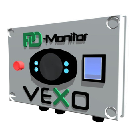
VEXO PD-Monitor User manual

www.VEXOint.com
technical@VEXOint.com
(269) 925-8812 PAGE 1
PD-MonitorTM
Pressure Dierential
Monitoring Unit
PD-MonitorTM O&M Manual
Last Updated - 08/17/2022
Product Code # 58760-PD
SET
OPERATION &
MAINTENANCE

PD-MonitorTM
Pressure Dierential
Monitoring Unit
www.VEXOint.com
technical@VEXOint.com
(269) 925-8812
PD-MonitorTM O&M Manual
Last Updated - 08/17/2022
Contents -
Liability
Warranty
Copyright
General Safety Instructions
Electrical Warning Symbol
Purpose & Use of this manual
Qualifications Required (assumptions)
Appropriate Use
Supplied goods
Transportation, Storage & Unpacking
Emergency Stop / Emergency Off
Personal Protective Equipment
Exceeding Permitted Pressure and/or Temperature Levels
Safeguards
External Forces
Electrical Equipment Inspections
Maintenance & Repair
Obvious Misuse
Product Description
Schematic Layout of Various Installations
Component List
Operating Principles
Markings
Installation
Electrical Connections & Wiring Diagram
Commissioning
VEXO™ iX-2 Controller
Monitoring & Parameters
Electrical Checks & Inspection
Decommissioning & Dismantling
General Access
Declaration of Conformity
Service History
........................................................................................................................................................................................
......................................................................................................................................................................................
....................................................................................................................................................................................
.................................................................................................................................................
..................................................................................................................................................
............................................................................................................................................
..........................................................................................................................
.......................................................................................................................................................................
........................................................................................................................................................................
............................................................................................................................
...................................................................................................................................
........................................................................................................................................
..................................................................................
..................................................................................................................................................................................
.........................................................................................................................................................................
.....................................................................................................................................
............................................................................................................................................................
.........................................................................................................................................................................
...............................................................................................................................................................
...................................................................................................................
........................................................................................................................................................................
..............................................................................................................................................................
......................................................................................................................................................................................
..................................................................................................................................................................................
....................................................................................................................
.........................................................................................................................................................................
...........................................................................................................................................................
......................................................................................................................................................
..........................................................................................................................................
......................................................................................................................................
.........................................................................................................................................................................
...................................................................................................................................................
..........................................................................................................................................................................
3
3
4
4
4
5
5
5
5
6
6
6
6
6
7
7
7
7
8
9
9
10
11
11
13
14
15
17
18
19
19
20
21
WARNING – This equipment must only be used, maintained or serviced by trained competent
operatives. If in any doubt please do not touch this equipment. Please contact VEXO International
or your reseller for additional advice, information and guidance.
PAGE 2

PD-MonitorTM
Pressure Dierential
Monitoring Unit
www.VEXOint.com
technical@VEXOint.com
(269) 925-8812
PD-MonitorTM O&M Manual
Last Updated - 08/17/2022
PAGE 3
Liability -
All technical information, data and information contained herein are correct at the time of
publication. To the best of our knowledge this information is the sum of our current findings
and experience. We reserve the right to make technical changes subject to the future
development of the VEXO™ product referred to in this publication. Hence no rights may be
derived from technical data, descriptions and illustrations. Technical pictures, drawings and
graphs do not necessarily correspond to the actual assemblies or parts as delivered.
Drawings and pictures are not to scale and may contain symbols for simplification.
Warranty -
Active Period: Manufacturing defects for 18 months from the date of manufacture or 12
months from the date of commissioning, whichever is sooner. This warranty covers
manufacturing defects only.
Please note that removal of the identification data labels from the equipment will render the
manufacturing warranty null and void. Manufacturing defects confirmed within the active
warranty period will be corrected at no charge.
The warranty is conditional upon the following clauses:
1.1 The equipment must be commissioned by a trained, competent technician or
qualified person, who can verify the integrity of the equipment at that time. The
qualified person must confirm in writing that the equipment is undamaged as a
result of transportation and installation and is fit to begin the warranty period.
1.2 Photographic evidence must be collected at the time of commissioning to verify the
condition of the equipment at that time.
1.3 A trained, competent technician or qualified person must test the equipment
annually.
1.4 This warranty covers the equipment against manufacturing defects. Normal wear
and tear is not covered by this agreement and should form part of a separate service
agreement.
1.5 The equipment must be stored, installed and operated in a frost-free and dry area.
Damage resulting from exposure to adverse temperatures or other adverse
environmental conditions will not be covered by this agreement.
1.6 Any and all non-warranty service visits and non-warranty inspection visits are
chargeable and are not covered by this warranty.
Any service costs are applicable if a defect or problem manifests as a direct result of the
connected system, misuse, incorrect handling, incorrect installation or incorrect
commissioning of the unit. Confirmed manufacturing defects will be addressed as per the
above. Additional remedial works due to the misuse, incorrect handling, incorrect installation
or incorrect commissioning of the unit remain chargeable.

PD-MonitorTM
Pressure Dierential
Monitoring Unit
www.VEXOint.com
technical@VEXOint.com
(269) 925-8812
PD-MonitorTM O&M Manual
Last Updated - 08/17/2022
PAGE 4
Copyright -
The information contained in this manual is confidential. The manual may be circulated
among authorized personnel only. It may not be distributed to third parties. All
documentation is protected by copyright. Distribution or other forms of reproduction of
documents, even extracts, exploitation or notification of the contents hereof is not permitted,
unless otherwise specified in writing by VEXO™ International (UK) Ltd. Infringements are
liable to prosecution and payment of compensation. We reserve the right to exercise all
intellectual property rights.
General Safety Instructions -
Disregard for, or lack of attention to, the information and measures contained in this manual
may pose a hazard to people, animals, the environment and tangible assets. Failure to
observe the safety regulations and the neglect of other safety measures may lead to the
lapse of liability for damages in the event of damage or loss.
DEFINITIONS:
Operator: Natural person or legal entity who owns and uses the product, or whom use of the
product has been entrusted to on the basis of a contractual agreement.
Principal: Legally and commercially liable client in relation to the system as a whole.
Responsible Person: The representative appointed to act by the installer or operator.
Qualified Person (QP): Any person whose professional training, experience and recent
professional activity aords them the requisite professional knowledge. This implies that
such people have knowledge derived from relevant national and internal safety regulations.
Electrical Warning Symbol -
Danger - Electric Current
Disregarding these warnings may:
• endanger health,
• cause death, fire or other damage,
• lead to the overloading of individual components
and to damage,
• or otherwise impair the unit’s function.
Caution - Warning for mistakes and wrong basic assumptions
Consider the implications of errors and incorrect set-up
conditions carefully!
Disregarding these warnings may lead to:
• serious personal injury,
• overloading of individual components and damage,
• impair the unit’s function.
DANGER 115V

PD-MonitorTM
Pressure Dierential
Monitoring Unit
www.VEXOint.com
technical@VEXOint.com
(269) 925-8812
PD-MonitorTM O&M Manual
Last Updated - 08/17/2022
PAGE 5
Purpose & Use of This Manual -
The following pages list the information, specifications, measures and technical data that will
allow relevant personnel to operate the product safely and for its intended purpose.
Responsible persons or those engaged by them, performing required services relating to this
product, must study this manual to ensure a good understanding of the information
contained herein. Such services include: storage, transportation, installation, electrical
installation, commissioning and re-starting, operation, maintenance, inspection, repair and
dismantling. Where the product is to be used in plants/facilities that do not comply with
harmonized regulations and relevant technical rules and guidelines of professional
associations for this field of application, the present document is purely for informative and
reference purposes. As this unit may be subject to unlimited inspection at all times, this
manual must be kept in the immediate vicinity of the installed unit, at least within the
confines of the operations room.
Qualifications Required, Assumptions -
All personnel must possess the relevant qualifications to carry out the required services, and
be physically and psychologically capable to do so eectively.
Operating instructions are transferred by VEXO™ representatives, or others assigned by
them, during delivery negotiations, or on demand. On-site requirements include logistics,
manual handling, and the preparation of an installation location with the requisite foundation
engineering to accommodate the unit and the requisite hydraulic and electrical connections,
the electrical installation for the power source of the equipment and installation of the BMS
signal leads if required.
Appropriate Use -
This equipment is designed for use on sealed and un-sealed thermal systems (heating, chilled
and condenser water). It is designed to confirm when a filter or item of equipment is blocked
with a designated dierential pressure rating and signal the fact with either an audible alarm,
strobe light and/or a BMS common alarm signal. The maximum operating water limits of this
equipment are 435 PSI.
Supplied Goods -
The items delivered must be compared against the items listed on the shipping note and
inspected for conformity. Unpacking, installation and commissioning may be started only
once the product has been checked as conforming with the intended use. In particular,
exceeding the permissible operating or design parameters may lead to malfunctioning,
component damage and personal injury. The product may not be used if circumstances are
not in line with our conformity statement, or if the delivery proceeded incorrectly in any
other manner.

PD-MonitorTM
Pressure Dierential
Monitoring Unit
www.VEXOint.com
technical@VEXOint.com
(269) 925-8812
PD-MonitorTM O&M Manual
Last Updated - 08/17/2022
PAGE 6
Transportation, Storage & Unpacking -
The equipment is delivered in packing units conforming to contract specifications, or
specifications required for certain transportation methods and climate zones. At a minimum,
packing units meet the requirements of VEXO™’s packaging guidelines. Important note:
Deliver the packed goods as close as possible to the installation location and make sure
there is a vertical, solid surface to which the goods can be mounted / secured.
Emergency Stop / Emergency Off -
The required EMERGENCY - STOP facility, in line with directive 2006/42EC, is present in the
main power switch on the front panel. Refer to the VEXO™ PD-Monitor™ Schematic, item 6
on page 9 of this document.
Personal Protective Equipment (PPE) -
To prevent or minimize the risk of personal injury, PPE must be used when doing potentially
dangerous work, or other activities, if alternative safety measures cannot be taken.
Any alternative safety measures must comply with the requirements set by the main
contractor or operator of the plant room, or the site in question. In the absence of alternative
safety measures, the minimum requirements for operating the product are safety goggles,
hand protection, well-fitting clothing and sturdy, closed and skid-proof footwear.
Exceeding Permitted Pressure and/or Temperature Levels -
Equipment used in combination with the VEXO™ PD-Monitor™ must guarantee that the
permitted operating temperature and the permitted medium temperature (heat transfer
medium) cannot be exceeded. Excess pressure and temperature may lead to component
overload, irreparable damage to components, loss of function, and as a result, may lead to
severe personal injury and damage to property.
These safeguards must be checked/inspected regularly. The ambient air temperature in
which the VEXO™ PD-Monitor™ is to be installed should be between 41°F and 113°F.
Safeguards -
The equipment supplied is equipped with the required safety devices. To test their
eectiveness or restore the original set-up conditions, the equipment must first be taken out
of service. Taking the system out of service implies that power should be isolated, hydraulics
isolated and then vented.
NOTE: Power supply must have suitable ground.

PD-MonitorTM
Pressure Dierential
Monitoring Unit
www.VEXOint.com
technical@VEXOint.com
(269) 925-8812
PD-MonitorTM O&M Manual
Last Updated - 08/17/2022
PAGE 7
External Forces -
Avoid any additional forces (e.g.: forces caused by heat expansion, vibration or dead weights
on the flow and return lines). These can lead to damage / leakage in water-bearing piping,
loss of stability of the appliance and potential failure of pressure bearing components.
Obvious Misuse -
• Operation at incorrect water pressures, voltage and/or frequency.
• Use in inappropriate system designs and environments.
• Use of non-permitted or inappropriate installation materials.
Electrical Equipment Inspections -
Routine maintenance and service inspections should be performed annually to insure that
the VEXO™ PD-Monitor™ continues to opperate correctly. An inspection should be carried
out every 12 months.
Maintenance & Repair -
Before any service work is to be performed on the VEXO™ PD-Monitor™, isolate and remove
all power from the system. Dawning the proper PPE for the area that the work is being
performed in. The VEXO™ PD-Monitor™ equipment must be taken out of service and guarded
against unintentional re-starting until the maintenance work is finished. When installed with a
VEXO™ X-POT™, the control panel can be interconnected to a BMS or alarm system to allow
for indication that the filter is ready for change and the magnets are ready for cleaning. The
VEXO™ iX-2 Controller is fitted with a combined visual illuminated flashing light in low light
situations for visual indication and audible alarm as an indication of filter blockage. The unit
must be inspected on an annual basis, and the electrical and mechanical components verified
for operation and integrity.
Task VEXO™ PD-Monitor™
Visual inspection of components 6 Months - Site technician
Operational check of hydraulic components 12 Months - Annual Service - Qualified Person
Operational check of electrical components 12 Months - Annual Service - Qualified Person

PD-MonitorTM
Pressure Dierential
Monitoring Unit
www.VEXOint.com
technical@VEXOint.com
(269) 925-8812
PD-MonitorTM O&M Manual
Last Updated - 08/17/2022
PAGE 8
Product Description -
The VEXO™ PD-Monitor™ is a packaged pressure dierential monitoring unit. It is a fully
assembled, factory tested, wall-mounted unit incorporating:
• 2# 4-20 milliamp pressure transducers.
• VEXO™ iX-2 12-volt Controller with RS485 MODBUS BMS connectivity - option.
• Strobe Light (Visual Warning Alarm).
• 5-Amp Relay for blocked filter and sensor fail alarm.
• MODBUS RS485 & 5-Amp Common Alarm Relay used to contact BMS System
(Normally Open)
• VEXO™ iX-2 Controller incorporates buzzer/sounder (mute button provided).
• Pre-set to 6 PSI pressure dierential.
• Working Pressure up to 435 PSI.
• Working fluid temperature -40°F up to 212°F
VEXO™ PD-Monitor™
VEXO™ PD-Monitor™ 115v 60Hz 13.5mA 1/4” NPT 54 T3.15 AL 115V 113°F
up to 435 PSI 2.9 lbs 7.9” 3.3” 5.9” 212°F 24.8°F
Model
Model Power Supply Transducer
Conn. IP-Rating Fuse Ref. Max. Ambient
Temp
Max. Working
Pressure Weight
Dimensions Max.
Working
Temp.
Min.
Working
Temp.
Width Depth Height

PD-MonitorTM
Pressure Dierential
Monitoring Unit
www.VEXOint.com
technical@VEXOint.com
(269) 925-8812
PD-MonitorTM O&M Manual
Last Updated - 08/17/2022
PAGE 9
Schematic Layout of Various Installations -
Components List -
7.9” 3.3”
3.5”
5.9”
PD-MONITORTM Controller Unit
Pressure Transducer Socket #1
Upstream of plant to be monitored
Pressure Transducer Socket #2.
Downstream of plant to be monitored
PD-MONITORTM Flashing Light
VEXO™ iX-2 12 Volt controller
(with MODBUS RS485 Connectivity)
PD-MONITORTM main electrical isolation
switch
3No. 16mm Cable gland.
Blank Gland for BMS Dry contact or BMS
Modbus RS485 via BACnet gateway
5.9’ Flying Cable for the Pressure
Transducers
Power to be connected to a suitable
115-120V/60 Hz, 15 amp grounded recepticle
Pressure Transducer #1 (Upstream)
Pressure Transducer #2 (Downstream)

PD-MonitorTM
Pressure Dierential
Monitoring Unit
www.VEXOint.com
technical@VEXOint.com
(269) 925-8812
PD-MonitorTM O&M Manual
Last Updated - 08/17/2022
PAGE 10
Operating Principle -
Operating Sequence Chart -
The VEXO™ PD-Monitor™ is designed to be a self-contained pressure dierential monitor and
alarm signalling device. It has a dedicated up-stream pressure transducer and down-stream
pressure transducer connection to a sealed or open vented system. As system fluid passes
through the hydraulic components in the flow sequence below, if the pressure detected
upstream and down-stream is out of the pre-set parameters within the VEXO™ iX-2
Controller, the alarm settings are activated to signal a blockage within the item of plant the
unit is monitoring.
Turn the power on.
Upstream water flow passes the upstream pressure transducer.
Upstream pressure transducer sends pressure data to controller.
Upstream water enters the plant item to be monitored.
Downstream water exits the plant item to be monitored.
Downstream flow passes the downstream pressure transducer.
Downstream pressure transducer sends data to the controller.
PD-Monitor™ Controller correlates up and downstream data.
If pressure is within parameter, no action is required.
If pressure falls outside of parameters, alarms are activated.
Strobe light flashes / buzzer sounds and BMS signal is sent.
If Pump is wired via PD Monitor, power is isolated via a relay
Maintenance required to clear the blockage.
Turn power o.
Blockage cleared.
Turn power back on.
1.
2.
3.
4.
5.
6.
7.
8.
9.
10.
11.
12.
13.
14.
15.
16
FLOW DIRECTION

PD-MonitorTM
Pressure Dierential
Monitoring Unit
www.VEXOint.com
technical@VEXOint.com
(269) 925-8812
PD-MonitorTM O&M Manual
Last Updated - 08/17/2022
PAGE 11
Markings -
The following markings and warnings are installed on the VEXO™ PD-Monitor™.
Installation (Basic Installation Requirements) -
The VEXO™ PD-Monitor™ controller unit (item 1) is to be positioned in a dry location and
fixed to a sturdy wall / frame as close as possible to the item of plant to be monitored. The
ambient air temperature in which the VEXO™ PD-Monitor™ is to be installed should be
between 41°F and 113°F. The pressure transducers need to be connected either side of an
item of plant which requires the pressure dierential to be monitored. Please note that the
pressure transducers are supplied with a 70.8” flying lead.
The VEXO™ PD-Monitor™ controller unit is supplied with a 3’, 3-wire grounded cord end (item
10). Suitable to be connected to any standard 15-amp grounded receptable. Power circuit
must have suitable ground.
Pressure Transducer 1 (item 11) is to be located up-stream of the plant item and Pressure
Transducer 2 (item 12) is to be located down-stream of the plant item. Each pressure
transducer has a 1/4” NPT thread for connecting to the system pipework with a suitable
sealing compound.
Each transducer is connected to the transducer cable (item 9) via a Packard plug (items 11 &
12). Ensure the cables from the Packard plug to the controller unit (item 1) are kept clear of
fouling, are secured to a hard surface, and that any spare cable is coiled and cable-tied. Keep
the transducer cable away from electrical mains cables where possible as this may interfere
with the current and provide false readings.
Mode/Type:
Technical Ratings:
Directives:
Year of Manufacture:
PD-Monitor™
Electrical 115v 60Hz 13.5mA IP54
Ambient Temp for Installation to >41°F to 212°F
Operating Temp: >40°F to 212°F
Low Voltage Directive 2014/35/EU
2022
VEXO International (UK) Ltd
6 Granary Building, Millow Hall Farm, Millow (Dunton),
Biggleswade, Bedfordshire, SG18 8RH. United Kingdom

PD-MonitorTM
Pressure Dierential
Monitoring Unit
www.VEXOint.com
technical@VEXOint.com
(269) 925-8812
PD-MonitorTM O&M Manual
Last Updated - 08/17/2022
PAGE 12
Installation (Critical Installation Requirements) -
Transducer Connections -
The equipment must be located:
• In a frost-free area (>41F), protected from adverse environmental conditions.
• In a well-lit area to allow for safe maintenance.
• On a flat, vertical, level, solid wall or frame with clear access of 7.9” all around the
controller unit.
Care must be taken when handling this equipment. Appropriate safety measures must be
in place in respect of use, handling and application of:
• Electrical equipment.
• Sealed system water.
• Hydraulic equipment.
It is essential to ensure the environment that this equipment is installed in is safe to work in
and is free from trip hazards.

PD-MonitorTM
Pressure Dierential
Monitoring Unit
www.VEXOint.com
technical@VEXOint.com
(269) 925-8812
PD-MonitorTM O&M Manual
Last Updated - 08/17/2022
PAGE 13
Electrical Connections & Wiring Diagram -
The provision of a power supply, (protective) ground wire connection, and line protection must
be made according to local regulations and the applicable building codes. Please check the
electrical ratings and requirements stated on the product label axed to the equipment. (Red
part numbers 02 and 03 above refer to the parts list on page 9 of this manual).
VEXO™ IX-2 CONTROLLER WIRING DIAGRAM
Blocked
Filter/Pump
Fail Alarm
5A MAX
Common
Alarm /
5A MAX
Pump
16A MAX
Connections
not used on
PD-Monitor™
13 14
A
B
MODBUS MODBUS
115V
115V
12V AC
T3.15AL 115V
3’ 115V
Power Cord (18AWG)
NEMA 5-15P
Unfused with
B Type Plug
MODBUS to BACnet or
other language gateway is
by others (as required)

PD-MonitorTM
Pressure Dierential
Monitoring Unit
www.VEXOint.com
technical@VEXOint.com
(269) 925-8812
PD-MonitorTM O&M Manual
Last Updated - 08/17/2022
PAGE 14
Commissioning -
WARNING: This equipment must only be used, maintained or serviced by trained, competent
operatives. If in any doubt please do not touch this equipment.
1. GENERAL
The VEXO™ PD-Monitor™ is a ‘Plug and Play’ unit. It is supplied factory set with the
Dierential Pressure set to 6 PSI. Refer to setting parameters on page 15 for changing the
dierential pressure.
The operator should read this section prior to hand-over of the equipment from the
installation operative to familiarize him/herself with the operating procedures of the VEXO™
iX-2 Controller and the VEXO™ PDMonitor™ unit as a whole.
The Control System is based around a VEXO™ iX-2 Controller complete with I/O modules. A
Display Panel is fitted to the VEXO™ iX-2 Controller to allow adjustment of the parameters.
In the event of a power failure, the VEXO™ iX-2 Controller will return to its last set operating
mode once power has been restored.
Ensure the power supply to the VEXO™ PD-Monitor™ is 115V ~ 1 N PE 60Hz via a suitable
Fused Spur.
The power supply to the VEXO™ PD-Monitor™ is provided from either a dedicated 115V
power supply or the system pump electrical supply that the VEXO™ PD-Monitor™ monitoring.
Therefore, the VEXO™ PD-Monitor™ will only be activated when the main system pump is
running and active. The power supply is then connected to the main VEXO™ PD-Monitor™
Mains Isolation Switch, refer to the unit schematic, item 10 on page 9 (Schematic) of this
document. The power is then distributed throughout the VEXO™ PD-Monitor™ via an internal
wiring loom.
2. VEXO™ PD-MONITOR™ SPECIFICATION:
• 2No ~ 4-20 milliamp pressure transducers monitor the pressure dierential on the inlet and
outlet of the X-POT side stream filter or the item of plant e.g. plate heat exchanger, pump
set etc.
• The VEXO™ iX-2 12-Volt Controller, with built-in buzzer, is located in the housing box with a
strobe and electrical isolation switch on the front.
• Power is supplied to the VEXO™ iX-2 controller via an internal 12-volt transformer which
receives its power from the 115V mains supply or via a dedicated spur from the system
pump which is serving the system the PD-Monitor™ is applied to.
• The VEXO™ iX-2 Controller has 2 relays within:
- 5-amp alarm relay for blocked filter alarm and sensor fail.
- 5-amp common alarm relay which can be configured to normally open or closed and
is to be used for a signal contact for a BMS system.
• When energized the VEXO™ iX-2 controller will start and display “Run”, the pressure
transducers upstream and down-stream of the X-POT or plant to be monitored will
monitor the pressure dierential across the X-POT or other plant item etc.

PD-MonitorTM
Pressure Dierential
Monitoring Unit
www.VEXOint.com
technical@VEXOint.com
(269) 925-8812
PD-MonitorTM O&M Manual
Last Updated - 08/17/2022
PAGE 15
• When the VEXO™ iX-2 controller senses the pre-set pressure dierential has been
achieved, the controller will display and scroll “Blocked Filter”. The VEXO™ iX-2 will then
power the strobe light and internal buzzer.
• To observe the pressure readings from the two pressure transducers:
• Press the “up” arrow (button 1) for sensor 1 up-stream pressure transducer reading.
• Press the “down” arrow (button 2) for sensor 2 down-stream pressure transducer.
3. ENABLE MONITORING
It is important to visually inspect the electrical connections, components and conduit serving
the VEXO™ PD-Monitor™ unit before commencement of the operation of the unit.
It is important to visually inspect the VEXO™ PD-Monitor™ unit hydronic connections before
commencement of the operation of the unit to confirm the following:
• The integrity of all fittings and pipework connecting the heating / chilled system to the
VEXO™ PD-Monitor™ – ensure that there are no leaks.
• When the system to be monitored has been filled and pressurized - check the hydraulic
integrity of all fittings.
4. ACTIVATION
The VEXO™ PD-Monitor™ can now be activated by pressing the Isolator Switch from the
‘O’ position to the ‘On’ position. The VEXO™ iX-2 Controller will now scroll the following...
VEXO™ PD-Monitor™ -
1. SETTING PARAMETERS
The Dierential Pressure
is factory set to 6 PSI.
To reset the parameters
(for example, the pressure
dierential) the following
sequence needs to be
followed on the VEXO™
PD-Monitor™:
• Press and hold “set” (button 4), for 5 secs to access the pressure dierential parameter.
• The first digit will start to flash o and on.
• Using the up arrow (button 1) or down arrow (button 2) enter code ‘815” by pressing “set”
(button 4) after each number has been assigned.
• When ‘815” has been achieved, press “set” (button 4) for 5 seconds.
• The current pressure dierential setting will appear.
BUTTON 1
BUTTON 2
BUTTON 3
BUTTON 4

PD-MonitorTM
Pressure Dierential
Monitoring Unit
www.VEXOint.com
technical@VEXOint.com
(269) 925-8812
PD-MonitorTM O&M Manual
Last Updated - 08/17/2022
PAGE 16
• The dierential pressure can now be changed to between 1 PSI and 101 PSI.
• Using the up arrow (button 1) or down arrow (button 2) enter the new desired pressure
dierential parameter.
• Hold “set” (button 4) for 5 seconds, this will store the new setting and re-boot the VEXO™
PD-Monitor™. The new setting will be saved and the controller will return to the main screen.
2. SETTING PARAMETERS
3. ALARM CONDITIONS
• If the PD-Monitor™ detects pressure outside of set parameters during normal operation,
fault condition will be initialised.
• In alarm conditions, the internal buzzer will sound on the controller. This can be muted by
pressing the mute (button 3).
• In alarm conditions, the strobe light will function.
• The VEXO™ iX-2 controller can be powered down by pressing electrical isolation switch on
the fascia to o.
• Once the alarm conditions and actions have been rectified, the controller can be reset by
re-powering the unit. To power up the unit, switch the electrical isolation switch on the
fascia to ‘on’.
• Monitoring will resume.
4. FAULT MESSAGES
The VEXO™ PD-Monitor™ display will scroll a fault message as below if a fault is detected.
The VEXO™ PD-Monitor™ will also initiate the visual strobe and sounder to alert the user.
If connected to a BMS, the VEXO™ PD-Monitor™ will alert the user with a “Common Fault”
signal.

PD-MonitorTM
Pressure Dierential
Monitoring Unit
www.VEXOint.com
technical@VEXOint.com
(269) 925-8812
PD-MonitorTM O&M Manual
Last Updated - 08/17/2022
PAGE 17
Fault Message
Blocked Filter
Sensor 1 Fail
Sensor 2 Fail
Fault Message
Isolate the PD-Monitor™ and clean/change filters to
allow PD-Monitor™ to operate
Call technician to check connections and replacement
of the pressure transducer
Call technician to check connections and replacement
of the pressure transducer
PD-Monitor™
Operation
Shutdown
Shutdown
Shutdown
Pump Fail (PD Monitor Only) Press and hold “set” (button 4), for
5 secs to access the parameter menu.
Shutdown
VEXO™ PD-Monitor™ Monitoring -
Volt-free contacts are provided for the following conditions. The contacts are rated 5 amp.
115V maximum.
Using the up arrow (Button 1) or down arrow (Button 2) enter code “815” by pressing
“Set” (Button 4) after each number has been assigned.
Press ‘Up arrow’ (Button 1) & ‘Set’ (Button 4) to cycle through parameters.
Cycle through until “P4” is shown (Pump Sense)
Depress ‘Set’ (Button 4) and use the up/down arrows to change “Y” to “N” (This
deactivates Pump Sense Mode).
Hold ‘Set’ (Button 4) for 5 seconds, this will store the new setting and re-boot the
VEXO™ PD-Monitor™. The new setting will be saved and the controller will return to the
main screen.
Filter On - VEXO™ PD-Monitor™ will scroll “Run”
during normal operation.
The screen scrolls:
VEXO™ PD-Monitor™ will scroll DP alarm as per message set up option i.e
“Blocked Filter” if a filter is blocked. (Filter Blocked, Clean/Replace Filters)
The screen scrolls:
VEXO™ PD-Monitor™ will scroll “Sensor 1 Fail” in the
event of an upstream pressure transducer failure
(Upstream Pressure Transducer Failure).
The screen scrolls:
VEXO™ PD-Monitor™ will scroll “Sensor 2 Fail” in the
event of a downstream pressure transducer failure
(Downstream Pressure Transducer Failure).
The screen scrolls:

PD-MonitorTM
Pressure Dierential
Monitoring Unit
www.VEXOint.com
technical@VEXOint.com
(269) 925-8812
PD-MonitorTM O&M Manual
Last Updated - 08/17/2022
PAGE 18
VEXO™ iX-2 Controller Parameters -
Electrical Checks & Inspection -
To stop electrical equipment (PD-Monitor™), shut o power to
the main control unit by pressing the Mains ON/OFF Power
Switch (6) to the OFF position. The power supply must remain
o for the entire duration of the check/inspection.
Electrical Checks & Inspection -
This equipment must only be used, maintained or serviced
by trained, competent operatives. If in any doubt please
do not touch this equipment.
Please contact VEXO™ or your reseller for additional
advice, information and guidance.
It is forbidden to alter or use non-original components or
replacement parts without written authorization. Such
acts may result in serious personal injury and endanger
operational safety. They will also render any claim for
damages against product liability void.

PD-MonitorTM
Pressure Dierential
Monitoring Unit
www.VEXOint.com
technical@VEXOint.com
(269) 925-8812
PD-MonitorTM O&M Manual
Last Updated - 08/17/2022
PAGE 19
At the end of the lifespan, or at the planned decommissioning of the equipment, please
ensure:
• that the PD Monitor is separated from the power supply.
• that the hydraulic system connections are closed o and isolated.
Caution: Water areas should first be vented and then emptied. This water may be conditioned,
contain anti-freeze or other substances and, as such, must be disposed of in accordance with
the local legislative requirements.
The destination of and further processing of the construction components should be carried
out in agreement with the relevant waste management service provider.
General Access -
SET
5.9”
5.9”
3.3”
7.9”
5.6”
3.8”
3.5”
0.3”
FRONT
BACK (Mounting Holes)
SIDE
PRESSURE SENSOR
1/4” NPT
THREAD
70.9”
PACKARD
PLUG
Leave at least 3.9” free space in all directions to ensure sufficient access and 7.9” from the front of the unit
to enable unhindered opening of the front service panel.

PD-MonitorTM
Pressure Dierential
Monitoring Unit
www.VEXOint.com
technical@VEXOint.com
(269) 925-8812
PD-MonitorTM O&M Manual
Last Updated - 08/17/2022
PAGE 20
Other manuals for PD-Monitor
1
This manual suits for next models
1
Table of contents
Other VEXO Measuring Instrument manuals