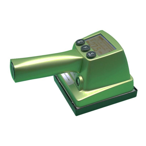
VF HF-50 User manual

VF1807090083 EN
revision
version 07
2019
HAND-FOOT CONTAMINATION
MONITORS
HF-50, HF-100, HF-150, HF-300, HF-350
HF-4A, HF-4B, HF-4C, HF-4D, HF-4E
Type: K1010, K1011, K1012, K1013, K1014,
K1175, K1176, K1177, K1178, K1179
VF, a.s.
Svitavská 588
CZ 679 21 Černá Hora
tel. +420 516 428 611
fax +420 516 428 610
www.vfnuclear.com
Instructions for Use

2

Table of Contents
VF1807090083 EN revision 3
Table of Contents
Table of Contents.................................................................................................. 3
List of Figures ....................................................................................................... 6
List of Tables......................................................................................................... 8
Foreword............................................................................................................... 9
1.Introduction..................................................................................................... 10
1.1. Instrument specifications 10
1.2. Abbreviations 10
1.3. Terms and definitions 11
1.4. Acts, regulations and standards 13
2.Occupational safety, fire protection and environmental impacts................... 14
2.1. Occupational safety 14
2.1.1 Safety signs used in VF, a.s. and their meanings................................................................. 14
2.1.2 Obligations of the operator ................................................................................................ 14
2.1.3 Qualification requirements of the staff................................................................................ 15
2.1.4 Conditions for the safe operation of electrical equipment ..................................................... 15
2.2. Fire protection 15
2.3. Environmental impact statement 15
2.4. Instrument disposal 16
3.Technical specification .................................................................................... 17
3.1. Surface Contamination Detector SCD-286 18
3.2. Surface Contamination Detector SCD-525 20
3.3. Smart Frisking Probe SFP-100 22
4.General description.......................................................................................... 25
4.1. Purpose of the instrument 25
4.2. Description of instrument 25
4.3. Design overview 27
4.3.1 Connectors, description and location .................................................................................. 30
5.Before putting the instrument into operation................................................. 31
5.1. Transportation 31
5.2. Initial preparation 31
5.3. Power supply 31

Table of Contents
VF1807090083 EN revision 4
5.4. Storage 32
5.5. Installation 32
5.6. Operation verification 34
5.6.1 Instrument actuation......................................................................................................... 34
5.6.2 Version with an identification card reader ........................................................................... 35
5.6.3 Turning off ....................................................................................................................... 35
5.6.4 Power failure .................................................................................................................... 35
5.6.5 Calibration of the PLC screen ............................................................................................. 36
5.6.6 Initial instrument settings .................................................................................................. 36
6.Instructions for use ......................................................................................... 37
6.1. Visual and acoustic signalization 37
6.2. Control elements 38
6.3. Basic screen 38
6.4. Contamination measurement procedure 39
6.4.1 Contamination detection by frisker ..................................................................................... 42
6.4.2 Display of measurement results ......................................................................................... 43
6.5. Service menu 44
6.5.1 Export archive, Export errors ............................................................................................. 46
6.5.2 Clear archive, clear archive of error.................................................................................... 48
6.5.3 Configuration export.......................................................................................................... 49
6.5.4 Configuration import ......................................................................................................... 50
6.5.5 Date and time................................................................................................................... 51
6.5.6 Ethernet setup .................................................................................................................. 52
6.5.7 Detectors status................................................................................................................ 52
6.5.8 Detectors response ........................................................................................................... 53
6.5.9 Reset ............................................................................................................................... 54
7.Instrument settings......................................................................................... 55
7.1. Setting the measurement parameters by means of the VF-Setup service software 55
7.2. Setting the measurement parameters by means of web interface 56
7.2.1 Instrument settings........................................................................................................... 58
7.2.2 Detectors settings ............................................................................................................. 60
8.Maintenance and care of the instrument ........................................................ 62
8.1. Daily maintenance 62
8.2. Quarterly maintenance 62
8.3. Annual and multi-annual maintenance 62
8.4. Protective foils of foot detectors 63
8.5. Cleaning the dirt tray for hand detectors 64
8.6. Checking the switches for foot detector grates 66

Table of Contents
VF1807090083 EN revision 5
8.7. Metrological traceability 67
8.8. Photomultiplier (PMT) life 68
9.Troubleshooting............................................................................................... 69
9.1. High background level 71
9.2. Possible detector contamination 72
9.3. Communication failure 73
10.Delivery parts................................................................................................. 74
10.1. Standard delivery parts 74
10.2. Accessories, additional equipment and related products delivered separately 74
10.3. Consumable material 74
11.Warranty conditions ...................................................................................... 75
12.Annexes ......................................................................................................... 77
Annex A. Block diagram of the HF monitor................................................................................ 77
Annex B. Spare parts for authorized service organization........................................................... 78
Annex C. Minimum settable alarm level versus background count rate........................................ 80
Annex D. I/O technology ......................................................................................................... 81
Annex E. Configuration file....................................................................................................... 82
Annex F. Detector status, detector supply, HV sources .............................................................. 83
Annex G. Unpacking instructions .............................................................................................. 84
Annex H. Packing instructions .................................................................................................. 88
Notes................................................................................................................... 94

List of Figures
VF1807090083 EN revision 6
List of Figures
Fig. 1 Hand-Foot Contamination Monitor ........................................................................................................ 25
Fig. 2 Structural lay-out.................................................................................................................................... 27
Fig. 3 Supply, protective and communication elements at the back of the instrument base .......................... 27
Fig. 4 Upper box with electronics .................................................................................................................... 28
Fig. 5 Voice module......................................................................................................................................... 28
Fig. 6 Dimensions of the variant with vertical layout of hand detectors .......................................................... 29
Fig. 7 Terminal connectors on the rear side of the box with the PLC ............................................................. 30
Fig. 8 Terminal connectors on the back of the base ....................................................................................... 30
Fig. 9 Location of the main switch on the back of the base of the instrument and variant with grommet....... 32
Fig. 10 Removal of the cover at the back part of the base and actuation of the FZ1 breaker ........................ 34
Fig. 11 Adjustable legs for proper positioning of the instrument ..................................................................... 34
Fig. 12 Display –Basic screen ........................................................................................................................ 35
Fig. 13 Display - Identification of the measured person .................................................................................. 35
Fig. 14 Calibration screen................................................................................................................................ 36
Fig. 15 Visual signalization.............................................................................................................................. 37
Fig. 16 Basic screen –Ready for measurement ............................................................................................. 38
Fig. 17 Signal of readiness for measurement.................................................................................................. 38
Fig. 18 Display –Instructions for the correct measurement position .............................................................. 39
Fig. 19 Display –Measurement in progress.................................................................................................... 40
Fig. 20 No contamination detected.................................................................................................................. 40
Fig. 21 Visual signalling –No contamination detected.................................................................................... 40
Fig. 22 Contamination signalled ...................................................................................................................... 40
Fig. 23 Display –measurement not completed............................................................................................... 41
Fig. 24 Display –Monitor contamination test .................................................................................................. 41
Fig. 25 Frisker.................................................................................................................................................. 42
Fig. 26 Detection of contamination by frisker –NOT CONTAMINATED......................................................... 42
Fig. 27 Detection of contamination by frisker –CONTAMINATED ................................................................. 42
Fig. 28 Display –Access to the Measurement results .................................................................................... 43
Fig. 29 Display –Measurement results........................................................................................................... 43
Fig. 30 Display –Enter to the Service menu................................................................................................... 44
Fig. 31 Display –Access to the Service menu................................................................................................ 45
Fig. 32 Display –Service menu options.......................................................................................................... 45
Fig. 33 Display - Service menu........................................................................................................................ 46
Fig. 34 Display –Export archive in progress................................................................................................... 47
Fig. 35 Display –Clear archive........................................................................................................................ 49
Fig. 36 Display - Clear error archive................................................................................................................ 49
Fig. 37 Display –Configuration export ............................................................................................................ 50
Fig. 38 Display –Configuration import ............................................................................................................ 51
Fig. 39 Display –Date and time setup............................................................................................................. 51
Fig. 40 Display –Network connection setup ................................................................................................... 52
Fig. 41 Display –Detectors status................................................................................................................... 52
Fig. 42 Detector response ............................................................................................................................... 54
Fig. 43 VF-Setup: Setting the communication................................................................................................. 55
Fig. 44 Web interface login form...................................................................................................................... 56
Fig. 45 Web interface - menu .......................................................................................................................... 57
Fig. 46 Web interface –Device parameters (page 1)...................................................................................... 58

List of Figures
VF1807090083 EN revision 7
Fig. 47 Web interface –Device parameters (page 2)...................................................................................... 58
Fig. 48 Web interface –Detectors settings...................................................................................................... 60
Fig. 49 Foil in a cardboard frame measurement for alpha radiation ............................................................... 63
Fig. 50 Optional accessories - foot detector protective foil or frame with a protective foil .............................. 63
Fig. 51 Orientation of protective foil on a paper reel ....................................................................................... 64
Fig. 52 Protective foil in a frame on the foot detector (with open protective grid)........................................... 64
Fig. 53 Cleaning the dirt tray for hand detectors ............................................................................................. 65
Fig. 54 Foot detectors basic maintenance....................................................................................................... 66
Fig. 55 Photomultiplier..................................................................................................................................... 68
Fig. 56 Typical dependence of the anode current of the photomultiplier over time ........................................ 68
Fig. 57 Display –Example of failure report...................................................................................................... 69
Fig. 58 Display –High background level......................................................................................................... 71
Fig. 59 Display –Detector contamination........................................................................................................ 72
Fig. 60 Display –Loss of communication with a detector ............................................................................... 73
Fig. 61 Block diagram of the HF monitor......................................................................................................... 77
Fig. 62 Background-Time dependence of MDA .............................................................................................. 80
Fig. 63 Diagram of the I/O connector .............................................................................................................. 81
Fig. 64 The “config.xml” sample configuration file ........................................................................................... 82

List of Tables
VF1807090083 EN revision 8
List of Tables
Tab. 1 EU guidelines and Government Orders ............................................................................................... 13
Tab. 2 Technical standards ............................................................................................................................. 13
Tab. 3 Overview of monitor types.................................................................................................................... 26
Tab. 4 Terminal connectors............................................................................................................................. 30
Tab. 5 Description of the terminal board XC1 ................................................................................................. 33
Tab. 6 Significance of visual signalling statuses .............................................................................................. 37
Tab. 7 Meanings of the columns in the table of measurement results............................................................ 44
Tab. 8 Text file format of the archive exported................................................................................................ 47
Tab. 9 The meanings of bits of the contamination measurement bit mask..................................................... 48
Tab. 10 The meanings of bits of the contamination measurement bit mask for the given detector................ 48
Tab. 11 The meanings of values in the table with the status of detectors ...................................................... 53
Tab. 12 Web interface –Device parameters................................................................................................... 59
Tab. 13 Web interface –Detectors settings .................................................................................................... 61
Tab. 14 Failure reports .................................................................................................................................... 70
Tab. 15 Detectors & addresses....................................................................................................................... 73
Tab. 16 Standard delivery parts ...................................................................................................................... 74
Tab. 17 Accessories and additional equipment delivered separately ............................................................. 74
Tab. 18 Consumable material ......................................................................................................................... 74
Tab. 19 Connection of an I/O connector for technology.................................................................................. 81
Tab. 20 Global status of the detector .............................................................................................................. 83
Tab. 21 Status of the detector´s supply......................................................................................................... 83
Tab. 22 Status of HV source ........................................................................................................................... 83

Foreword
VF1807090083 EN revision 9
Foreword
Read carefully the Instructions for Use before using the HF Hand-Foot Contamination Monitor and follow its
suggestions.
The information contained in these Instructions for Use is the exclusive property of VF, a.s., and may not be
modified, copied or disclosed to third parties without the company's knowledge.
Failure to follow the instructions and safety warnings contained herein may be considered a breach of warranty
conditions and may lead to the termination of warranty period.
The manufacturer reserves the right to perform technical, visual and functional changes to the design of the
instrument without prior notice as part of its programme of continuous development and improvement of its
products.
The Instructions for Use form an integral part of the instrument.
The radiometric parameters are described in detail in separate documents.

Introduction
10
1. Introduction
1.1. Instrument specifications
The HF series hand-foot contamination monitors are intended to measure surface contamination by alpha,
beta and gamma emitting radionuclides on hands, feet, and clothing.
Typical usage is at nuclear power plants, radio-chemical plants, research institutes, hospitals, etc.
1.2. Abbreviations
A
Activity
As
Surface activity
CRM
Certified reference material
DLM
Detection limit
DTR
Decision threshold
k1-
Coefficient of an error of the first kind (a "false positive")
k1-β
Coefficient of an error of the second kind (a "false negative)
LV
Alarm level
N
Number of pulses
n
Count rate
PC
Personal computer
PCB
Printed circuit board
PLC
Programmable Logic Controller
PMT
Photomultiplier
q2π
Emission form surface
R
Response of instrument
RF
Response factor
RS-232 (485)
Serial Interface
SW
Software
USB
Universal Serial Bus
ZnS(Ag)
Zinc sulphide activated with silver (scintillation material for detecting alpha radiation)
δ
Relative basic error
Φ2π
Instrument efficiency

Introduction
VF1807090083 EN revision 11
1.3. Terms and definitions
Activity
A quotient of the mean number of spontaneous nuclear transitions from an energy state
in an amount of radionuclide in a time interval. The unit is [Bq].
Alarm level
Value (threshold) that is preset inside the instrument. If this value is exceeded, the alarm
will be activated. Both the acoustic and visual alarms can be activated. The units are
usually [cps, Bq, (Bq∙cm-2), Gy/h, Sv/h].
Background
Radiation field in which the instrument should operate, and which involves both the
natural background and the radiation caused by other sources that can be present in the
vicinity of the instrument. The following units, depending on the instrument type, are
usually used [cps, Bq, (Bq∙cm-2), Gy/h, Sv/h].
Certified Reference
Material (CRM)
Material provided with a certificate whose one or more properties are sufficiently
homogeneous and determined at a sufficient level for calibrating an appropriate
instrument. These properties are certified by a procedure that determines traceability on
the precise implementation of the unit in which the value of properties are described, and
each certificated value is accompanied by an uncertainty at a given confidence level.
Coefficient of the error
of the first kind (Type I
error)
Determines the probability that the true activity of the sample measured is zero, and
the instrument indicates contamination.
Coefficient of the error
of the second kind
(Type II error)
Determines the probability that the true activity of the sample measured is greater than
zero, and the instrument indicates no contamination (clean).
Contamination meter
Instrument intended for the measurement and evaluation of surface contamination that
contains visual indication and acoustic signalization of count rate. The acoustic
signalization can be switched off.
Contamination monitor
Instrument intended for the measurement and evaluation of surface contamination,
and additionally to the visual indication and acoustic signalization of the count rate,
the instrument is provided with acoustic signalization of exceeding the preset
contamination level (threshold).
Count per second;
Count rate
Number of counts per time unit. The units are usually [cps, cpm].
Decision threshold
Critical value of the statistical test for making a decision if the measured count rate of
a potentially contaminated person is at the background level, or the measured count rate
is higher than the background. The unit is [cps].
Detection limit
The mean count rate for which the probability that the net count rate measured is lower
than the decision level is just equal to beta. The beta parameter means the coefficient
of a type II error. The unit is [cps].
Direct measurement of
surface contamination
Surface activity measurement by means of a contamination meter/monitor.
Effective measurement
range
Range of the quantity measured in which operating values of the meter or the monitor
meet the requirements of valid standards for the given type of instrument.
Efficiency
Ratio of the corrected count rate of the measuring instrument to the surface emission.
The unit is usually [%].
Indirect evaluation of
surface contamination
Assessment of removable contamination by means of wipe (smear, swab) test samples.
Photomultiplier (PMT)
The electric component that is able to detect very low intensity light signals. When a
photon impacts on the sensitive photocathode, electrons are emitted due to the
photoelectric effect, which are gradually magnified by electric voltage among the individual
electrodes (i.e. dynodes). The accelerated electrons that impact on the dynodes emit a
high number of electrons (the secondary emission), which results in the magnified electron
flux that impacts on the anode. PMTs are mainly used in scintillation detectors.

Introduction
VF1807090083 EN revision 12
Pulse count
The total number of counts per preset time interval.
Reference background
Background that simulates the ambient background for which the instrument is specified.
The decision making level and the detection limit are usually determined for a typical value
of the reference background of 100 nGy/h, unless stated differently.
Relative intrinsic error
Relative error of an instrument that is related to the given quantity when exposed to the
specific reference radiation under the specified reference conditions. It is expressed in
[%].
Response factor
Reciprocal value of the instrument response. The units are usually [Bq/cps], [(Bq∙cm-
2)/cps].
Response of instrument
Ratio of the corrected count rate of the measuring instrument to the measured quantity
(activity, surface activity, dose rate, etc.). The unit of response to activity is usually
[cps/Bq], to surface activity [cps/(Bq∙cm-2)] and to dose rate [cps/(Sv/h)],[cps/(Gy/h)].
Sensitive area of the
detector
Detector area, which is defined by the producer, with a response to small area source
(CRM) higher than 50 per cent of the maximum response. The unit is usually
[cm2].
Surface activity
Quotient of the activity of the radionuclide present on the surface and area for this
surface. The unit is usually [Bq∙cm-2].
Surface contamination
Radioactive surface contamination.
Surface emission
The number of particles of a certain type emitted from the source surface or its active part
per time unit. The unit is [1/s].
Zinc sulphide ZnS(Ag)
ZnS(Ag) is the inorganic salt of hydrosulphuric acid and zinc hydroxide activated by silver
(Ag). It is a white and crystalline substance which is not soluble in water, similarly as the
majority of sulphides. A charged alpha particle imparts its energy to the scintillation
centres that contain the atoms of silver. This leads to ZnS luminescence and photon
emission with a maximum wavelength of 450 nm.

Introduction
VF1807090083 EN revision 13
1.4. Acts, regulations and standards
The acts, regulations and standards provided herein are valid in the European Union. The instrument meets
and follows the directives and government regulations referred to in Tab. 1 as well as the harmonized technical
standards referred to in Tab. 2.
Identification/year of publication
Name
Directive 2014/35/ES
LV electrical equipment safety
Directive 2014/30/ES
Electromagnetic compatibility
Tab. 1 EU guidelines and Government Orders
Identification
Name
EN 61098
Radiation protection instrumentation. Installed personnel surface contamination monitoring
assemblies
EN 60325
Radiation protection instrumentation. Alpha, beta and alpha/beta (beta energy > 60 keV)
contamination meters and monitors
ISO 8769
Reference sources - Calibration of surface contamination monitors - Alpha-, beta- and photon
emitters.
ISO 31-10
Quantities and units - Part 10: Nuclear reactions and ionizing radiations
ISO 11929-1
Determination of the detection limit and decision threshold for ionizing radiation
measurements. Fundamentals and application to counting measurements without the
influence of sample treatment
IEC 980
Recommended practices for seismic qualification of electrical equipment of the safety system
for nuclear generating stations
EN 60068-2-6
Environmental testing: Tests - Test Ea and guidance - Vibration (sinusoidal)
EN 60068-2-27
Environmental testing: Tests - Test Ea and guidance - Shock
ISO 7441
Corrosion of metals and alloys - Determination of bimetallic corrosion in atmospheric
exposure corrosion tests
CSN 33 2000-6
Low voltage electrical installations - Revisions
CSN 33 2000-4-41
Low voltage electrical installations - Protection for safety - Protection against electric shock
CSN 33 1500
Electrotechnical and engineering regulations. Inspection and testing of electrical installations
EN 55022
Information technology equipment –Radio disturbance characteristics –Limits and methods
of measurement
EN 61000-6-1
Electromagnetic compatibility: Generic standards - Immunity for residential, commercial and
light-industrial environments
EN 61000-6-2 ed.3
Electromagnetic compatibility: Generic standards - Immunity for industrial environments
EN 61000-6-3 ed.2
Electromagnetic compatibility: Generic standards - Emission standard for residential,
commercial and light-industrial environments
EN 61000-6-4 ed.2
Electromagnetic compatibility: Generic standards - Emission standard for industrial
environments
Tab. 2 Technical standards

Occupational safety, fire protection and environmental impacts
VF1807090083 EN revision 14
2. Occupational safety, fire protection and environmental
impacts
2.1. Occupational safety
A summary of measures laid down by legislation and recommended by the producer that should prevent risk
or detriment to human health in work.
2.1.1 Safety signs used in VF, a.s. and their meanings
Attention, electrical equipment.
The appliance is supplied by AC voltage
mains
Do not dispose of with regular
waste.
Do not extinguish with either water or
foam extinguishers!
Ground point.
Warning and safety precautions.
Product compliance with EU
legislation.
Information, recommendations
and comments of the manufacturer.
Do not enter on the stand with the
shoes whose soles can pass through
the grating.
The stainless grating has dimensions
of the holes 30 x 30 mm.
2.1.2 Obligations of the operator
The operator is obliged to ensure the observation of general safety regulations when working with
the instrument.
To provide for the transport of the instrument, the operator is obliged to ensure training for
operating personnel in load lifting and slinging.
Before the instrument is put into service, the operator is obliged to define the competences
of persons for the operation, service, cleaning, regular maintenance, setting and adjustment
to provide and maintain the proper function of the instrument and the safety of persons and
property.

Occupational safety, fire protection and environmental impacts
VF1807090083 EN revision 15
2.1.3 Qualification requirements of the staff
The instrument may only be installed by a person familiar with the operational, safety and any
other regulations relating to work safety, in force in the place of location of the instrument or
otherwise associated with the place of work. Electric systems may only be installed and
connected by a person qualified in compliance with the applicable legislation of the country of
operation of the instrument.
The instrument may only be opened, set up and adjusted by persons who are physically and
mentally fit, older than 18 years of age, demonstrably trained by their parent organization
in the respective work and familiar with the Instructions for Use, which must be kept in an
accessible place.
2.1.4 Conditions for the safe operation of electrical equipment
Keep the safety labels, symbols and notices legible on the equipment.
Follow the relevant regulations for health and safety at work and the valid local standards laying
down the conditions for the electrical connections of electrical equipment and for their reliable and
safe operation.
Installation, operation and maintenance may only be provided by persons qualified for such
activities in compliance with the valid legislation of the country of operation of the instrument.
Perform inspections of electrical equipment on a regular basis, as required by the internal rules of
the organization or by applicable standards or guidelines of the manufacturer. Inspections may only
be performed by persons qualified for such activities in compliance with the legislation of the
country of operation of the instrument.
All activities related to the electrical equipment must be performed in compliance with
the Instructions for Use.
Any interventions in the design of the device ARE NOT ALLOWED.
Maintenance, cleaning and repair of the device can only be carried out with the power supply
disconnected and technological equipment switched off.
If you detect a failure or damage that you consider a threat to health and safety at work, do not
use the instrument and report the failure to the operator immediately.
The Instructions for Use must always be available for all persons performing activities
associated with the installation, operation and maintenance of the electrical equipment.
2.2. Fire protection
ATTENTION, electrical device, do not extinguish with water or foam extinguishers.
The instrument and its operation do not increase fire risk.
2.3. Environmental impact statement
The instrument as such and its operation do not cause any environmental load.

Occupational safety, fire protection and environmental impacts
VF1807090083 EN revision 16
2.4. Instrument disposal
When disposing of the instrument after the expiration of its life, you must follow applicable local
legislation1.
VF, a.s. is involved in the RETELA collective take-back system for the manufacturers
of electrical instruments. For more information on the RETELA system, please visit
http://www.retela.cz/ as well as http://www.weee-forum.org/.
1
In the Czech Republic, proceed in accordance with Act No. 185/2001 Coll., on Waste, as amended, and the related decrees of the
Ministry of the Environment.

Technical specification
VF1807090083 EN revision 17
3. Technical specification
Hand-Foot Contamination
Monitor
(4 vertical hand detectors)
HF-50
HF-100
HF-150
HF-300
HF-350
Type
K1010
K1011
K1012
K1013
K1014
Hand-Foot Contamination
Monitor
(2 horizontal hand
detectors)
HF-50
HF-100
HF-150
HF-300
HF-350
Type
K1175
K1176
K1177
K1178
K1179
Only figures with tolerances or limits are guaranteed data; any other values are only informative.
Detector parameters are described in detail in a separate document “Hand-Foot Contamination Monitor -
Radiometric Parameters” which forms an integral part of the Instructions for Use.
Basic data
Dimensions (W x H x D) - variant
with horizontal hand detectors
(599 x 1438 x 732) mm
(23⅝ x 56½ 29 in)
Dimensions (W x H x D) - variant
with vertical hand detectors
(822 x 1438 x 825) mm
(32⅜ x 56½ 32½ in)
Weight
52 kg (114.6 lb)
Power supply
(100 ÷ 240) V AC, (45 ÷ 65) Hz
Maximum input power
50 W (typical current consumption of the instrument is 0.2 A / 230 V)
Electric protection
IP 20
Number of detectors
6 (7)
4 x SCD-286 (hand detectors), HF-4 series: 2 x SCD-286
2 x SCD-525 (foot detectors)
1x SFP-100 (frisker) –optional accessories
Communication with PC
1 x Service USB port, 1 x USB port for data import/export,
1 x Ethernet 10/100
Result indications
Display
Colour touch-screen (320 x 240) pixels
Visual signalization unit
Indicator lamp 24 mm, minimum luminous intensity 900 mCd
Acoustic signalization unit
Voice output
Incoming pulse signalization unit for a frisker

Technical specification
VF1807090083 EN revision 18
Environmental conditions
Range of working temperatures
(0 ÷ +40) °C (32 ÷+104 °F)
Working relative humidity
max. 90 %, non-condensing
Working pressure
(86 ÷ 106) kPa
Storage conditions
Range of storage temperatures
(-25 ÷ +40) °C (-13 ÷+104 °F)
Storage relative humidity
max. 90 %, non-condensing
Other storage conditions
The instrument should not be stored without switching on for more than 3 months.
Note on symbols used in the tables below:
×The physical nature of the detector does not allow determination of the parameter.
- The parameter has not been determined yet.
3.1. Surface Contamination Detector SCD-286
Detectors specification
Detected radiation
SCD-286A: Alpha in one channel
SCD-286B: Alpha + Beta in one channel
SCD-286C: Alpha / Beta in two channels
SCD-286D: Alpha + Beta + Gamma in one channel
SCD-286E: Alpha / Beta+Gamma in two channels
Scintillators
SCD-286A: ZnS(Ag) on acrylic glass, 1.5 mm thickness.
Surface density of the scintillator (3.25 ± 0.25) mg∙cm-2
SCD-286B: plastic scintillator of 0.25 mm thickness
SCD-286C: ZnS(Ag) on a plastic scintillator of 0.25 mm thickness.
Surface density of the scintillator ZnS(Ag) (3.25 ± 0.25) mg∙cm-2
SCD-286D: plastic scintillator of 5 mm thickness
SCD-286E: ZnS(Ag) on a plastic scintillator of 5 mm thickness.
Surface density of the scintillator ZnS(Ag) (3.25 ± 0.25) mg∙cm-2
Photomultiplier
Diameter 25 mm with hemispheric window
High voltage source
(400 ÷ 1000) V with sensitive current limitation
Sensitive area of the detector
(130 x 220) mm = 286 cm2(44.3 in2)
Window
Aluminized light-tight foil (3 x 0.29) mg∙cm-2
Protective grid
Hexagonal grid, permeability 78 %
Dead time
Automatically compensated, typically 4.6 μs

Technical specification
VF1807090083 EN revision 19
Radiometric parameters
Parameter
Detector
Measurement range
Detector background
Measurement ranges
(for background 100 nGy/h)
SCD-286A
4 cps to 100 kcps
< 0.1 cps, typically 0.04 cps
SCD-286B
6 cps to 100 kcps
< 20 cps, typically 10 cps
SCD-286C (alpha)
4 cps to 100 kcps
< 0.2 cps, typically 0.08 cps
SCD-286C (beta)
6 cps to 100 kcps
< 20 cps, typically 10 cps
SCD-286D
15 cps to 100 kcps
< 75 cps, typically 37 cps
SCD-286E (alpha)
4 cps to 100 kcps
< 0.3 cps, typically 0.14 cps
SCD-286E (beta + gamma)
15 cps to 100 kcps
< 75 cps, typically 37 cps
Displayed quantities
Pulse rate [cps], activity [Bq], surface activity [Bq.cm-2]
Relative intrinsic error
±25 %
Reference radionuclide
241Am (alpha), 36Cl (beta)
Time constant
Variable (3 ÷ 10) s
Homogeneity
The minimum response must be greater than half the maximum response measured
across the entire sensitive area of the detector, i.e. the deviation must be less than 50
%, typically 25 %.
Crosstalk from alpha channel to
beta (beta-gamma) channel, for
types SCD-286C, SCD-286E
< 30 %, typically 6 %
Overload
Indication of overload when the measurement range is exceeded up to 100 x the
upper limit.
Affecting radiation
Detector
SCD-286A
SCD-286B
SCD-286C
SCD-286D
SCD-286E
Channel
alpha
alpha
+beta
alpha
beta
alpha+beta
+gamma
alpha
beta
+gamma
Alpha (241Am) [cps/Bq]
×
×
×
-
×
×
-
Beta (90Sr+90Y) [cps/Bq]
-
×
-
×
×
-
×
Gamma (137Cs)
[cps/(μGy/h)]
-
1.2.102
-
9.9.101
1.1.103
-
1.1.103

Technical specification
VF1807090083 EN revision 20
3.2. Surface Contamination Detector SCD-525
Detectors specification
Detected radiation
SCD-525A: Alpha in one channel
SCD-525B: Alpha + Beta in one channel
SCD-525C: Alpha / Beta in two channels
SCD-525D: Alpha + Beta + Gamma in one channel
SCD-525E: Alpha / Beta+Gamma in two channels
Scintillators
SCD-525A: ZnS(Ag) on acrylic glass, 1.5 mm thickness.
Surface density of the scintillator ZnS(Ag) (3.25 ± 0.25) mg∙cm-2
SCD-525B: plastic scintillator of 0.25 mm thickness
SCD-525C: ZnS(Ag) on a plastic scintillator of 0.25 mm thickness.
Surface density of the scintillator (3.25 ± 0.25) mg∙cm-2
SCD-525D: plastic scintillator of 5 mm thickness
SCD-525E: ZnS(Ag) on a plastic scintillator of 5 mm thickness.
Surface density of the scintillator ZnS(Ag) (3.25 ± 0.25) mg∙cm-2
Photomultiplier
Diameter 25 mm with hemispheric window
High voltage source
(400 ÷ 1000) V with sensitive current limitation
Sensitive area of the
detector
(150 x 350) mm = 525 cm2(81.4 in2)
Window
Aluminized light-tight foil (3 x 0.29) mg∙cm-2
Protective grid
Hexagonal grid, permeability 78 %
Dead time
Automatically compensated, typically 4.6 μs
This manual suits for next models
18
Table of contents
Other VF Measuring Instrument manuals