VHH B5HW User manual

ROUNDFILTER COFFEE BREWER AND HOT WATER DISPENSER WITH CONNECTION TO
THE WATER MAINS
OPERATING INSTRUCTIONS
700.403.148 G
VHH

Fig. 1
13 14 16 1 2 3
4
5
6
7
8
9
10111512
0
1
1
0
13
13.7
13.6
13.1
13.2
13.3
13.413.5

Fig. 2
A
D
E
E
B
C
J1
G
F
G2
HJ2
B5HW B10HW B20HW
A760 935 1145
B580 580 890
C800 835 955
D--- 1020 1226
E130 130 250
F32 32 32
G1 195 195 210
G2 --- 200 210
H90 90 90
J1 230 255 255
J2 --- 285 255

1
OPERATING INSTRUCTIONS (ENGLISH)
To operate hot water boiler and the coffee brewing machine properly and safely, read the following
instructions carefully.
INTRODUCTION
These machines, models B5-HW, B10-HW and B20-HW are combined hot water dispenser and coffee
brewing machines, with connection to the water mains. The machines are electronically controlled. The
hot water system mainly consists of a water reservoir with heating elements. In the water dispenser the
water is kept at a previously determined temperature. The water will be heated when the water dispenser
is switched on. Via taps (no. 15, fig. 1) the hot water can be tapped for a cup or a jug of tea.
Once the water in the reservoir is at the correct temperature, the temperature of the water drawn off will
always be correct when the dispenser is being used. The reservoir is only refilled when all the water
present is at the desired temperature. When the temperature drops too far as a result of additional cold
water, the refilling procedure is stopped. The water is first heated before proceeding further.
The coffee brewing machine works with a flow-trough heater. Through the outlet in the swivel-arm hot
water is led into the filter unit where it filters through the coffee.
The swivel-arm is equipped with a safety device, so when the swivel-arm is not in the right position above
the filter unit the hot water stops running. When filtered the coffee is collected in the coffee container from
which it can be taken via the drip free taps. To keep the coffee in the containers at the right temperature
heating elements are built in. The container heaters can be turned on and off independently of the rest of
the machine by a switch at the front of the container.
Figure 1:
1. Swivel-arm
2. Column
3. Cover filter unit
4. Filter unit
5. Container
6. Gauge
7. Tap
8. Container switch
9. Base
10.Drip tray
11.Socket
12.Drain
13.Control panel hot water dispenser and
coffee brewer
13.1 "In operation" signal
13.2 "Temperature too low" signal
13.3 Selection buttons 1 l. to 5 l. (B5HW)
13.4 Selection buttons 2.5 l. to 10 l. (B10HW)
13.5 Selection buttons 5 l. to 20 l. (B20HW)
13.6 Stop button
13.7 Descaling indicator
13.8 Switch coffee brewer
13.9 Switch hot water dispenser
14. Swivel-arm outlet
15.Tap hot water dispenser
16.Cover hot water dispenser
Figure 2 shows the dimensions of the combined hot water dispenser and coffee brewing machines.
Accessories
Connection hose Washing up brush
Funnel Level gauge brush
Drain hose Cleaning spring

2
Technical data
Model : B5-HW B10-HW B20-HW
Capacity hot water dispenser : 5,2 litres idem idem
Capacity coffee brewer : 2 x 5 litres 2 x 10 litres 2 x 20 litres
Cord length : ca. 140 cm idem idem
Water connection : via hose with idem idem
coupling nut G 3/4"
B5-HW:
Supply voltage
(50/60 Hz)
Rating
Coff. Brew
Rating
HW Disp.
Total
Rating
Max.
Protection
230 V/400 V3N~ 3100 W 2200 W 5300 W 32A/25A/16A
230 V/400 V3N~ 3100 W 2200 W 3100 W * 32A/25A/10A
200 V3~ 2350 W 1700 W 4050 W 25A
200 V3~ 2350 W 1700 W 2350 W * 16A
(Model with 2
elements in HW-
dispencer)
230 V/400 V3N~ 3100 W 5500 W 8600 W 32A/20A
230 V/400 V3N~ 3100 W 5500 W 5500 W * 10 A
200 V3~ 2350 W 4200 W 6550 W 32 A
200 V3~ 2350 W 4200 W 2350 W * 16 A
(Model with 5
elements in HW-
dispencer)
B10-HW:
Supply voltage
(50/60 Hz)
Rating
Coff. Brew
Rating
HW Disp.
Total
Rating
Max.
Protection
230 V/400 V3N~ 6600 W 2200 W 8800 W 32A/25A/16A
230 V/400 V3N~ 6600 W 2200 W 6600 W * 32A/25A/10A
200 V3~ 5000 W 1700 W 6700 W 25A
200 V3~ 5000 W 1700 W 5000 W * 16A
(Model with 2
elements in HW-
dispencer)
230 V/400 V3N~ 6600 W 5500 W 12100 W 32A/20A
230 V/400 V3N~ 6600 W 5500 W 6600 W * 10 A
200 V3~ 5000 W 4200 W 9200 W 32 A
200 V3~ 5000 W 4200 W 5000 W * 16 A
(Model with 5
elements in HW-
dispencer)
B20-HW:
Supply voltage
(50/60 Hz)
Rating
Coff. Brew
Rating
HW Disp.
Total
Rating
Max.
Protection
230 V/400 V3N~ 9100 W 2200 W 11300 W 32A/25A/16A
230 V/400 V3N~ 9100 W 2200 W 9100 W * 32A/25A/10A
200 V3~ 6900 W 1700 W 8600 W 25A
200 V3~ 6900 W 1700 W 6900 W * 16A
(Model with 2
elements in HW-
dispencer)
230 V/400 V3N~ 9100 W 5500 W 14600 W 32A/20A
230 V/400 V3N~ 9100 W 5500 W 9100 W * 10 A
200 V3~ 6900 W 4200 W 11100 W 32 A
200 V3~ 6900 W 4200 W 6900 W * 16 A
(Model with 5
elements in HW-
dispencer)
* = Model with preferential switching coffee brewer.
MACHINES WITH PREFERENTIAL SWITCHING
In machines with preferential switching the hot water dispenser and the sockets will be switched off
during a coffee brewing cycle. (Only when the flow through heater is switched on).

3
Warnings !
For safe operation of the water dispenser, pay
close attention to the following points:
1. When the appliance is in operation, some
components will get very hot.
2. If the appliance is unused for a longer period
of time, it is advisable to disconnect the
electricity and close the water supply.
3. Never use a sharp object to operate the
selector buttons.
4. Under normal circumstances, a small quantity
of water always remains in the appliance.
Please keep this in mind if it is to be exposed
to temperatures below 0 °C.
5. If all water has been removed from the
machine, the "Initial Operating Procedure"
will have to be repeated.
6. Stay with the appliance during
maintenance operations (such as
descaling).
7. When working with strong cleaning or
descaling agents, it is most advisable to
wear safety goggles (face protector) and
gloves.
8. After working with strong cleaning or descaling
agents, be sure to wash your hands.
9. Never immerse the appliance in water.
10. Prevent spillage of the descaler solution on
to the outside of the machine, this can cause
permanent damage to the exterior surface of
the machine housing. In the event of a
spillage, wipe area affected dry, whilst
observing the safety regulations as given in
the Users Instructions. Directly afterward the
area must be cleaned thoroughly.
11. Make sure that all repairs are carried out by
qualified technicians.
12. When the appliance has to be opened for
repairs or maintenance, be sure to
disconnect the electricity.
13. The appliance must always be connected to
the mains in such a way that it can be easily
disconnected.
14. The appliance should be connected to the
water mains with the hose attached to a
hand-operated tap.
15. The appliance must be earthed.
16. When installing the machine, always use
approved materials and parts.
17. Be sure to observe local regulations and
standards when installing the appliance.
18. The swivel-arm is equipped with a safety
device; When the swivel-arm is moved while
brewing coffee the programme is stopped,
an acoustic signal sounds and the indicator
light in the switch will start blinking.
19. When turned in the right position again the
stopped programme will continue.
20.When the swivel-arm is not in the right
position the hot water stops running.
21.ATTENTION! The safety device gives no
protection against putting the coffee
maker to work while there is no filter unit
and/or container placed underneath the
swivel-arm.
22.The manufacturer accepts no liability for any
damage resulting from installation, use or
maintenance activities that have not be
described in this manual.
23. The containers should only be moved when
empty.
24. If the containers are filled they should only
be transported by use of a trolley system.

4
INSTALLATION AND INITIAL OPERATING
PROCEDURE
When installing the appliance, keep the
warnings from the INTRODUCTION in mind.
1. Place the machine on a solid flat and
horizontal surface, in such a position that the
connections with the electric and water
mains can be made.
2. Connect the hose to the machine and the
water mains and connect the cable to the
electric supply according to the attached
instructions.
3. Place the containers with the filter units on
top, on the base and put the plugs in the
sockets (no. 11, fig.1) on the column.
4. Position the swivelarm in the correct position,
this is with the outlet over the opening in the
filter cover (fig. 3).
5. Turn the machine on by placing the switch of
the container and the coffee brewer in the
on-position (No.8 and 13.6, fig.1). The
indicator light in the switch will be illuminated.
6. The containers and filter units should be
rinsed with hot water.
7. Therefore press the 5, 10 or 20 l. selection
button. The indicator light in the switch will
be illuminated. The container will now be
filled with hot water.
When the program stops the indicator light in
the switch goes out and after 1 min. 3 times
an acoustic signal sounds.
8. Position the swivel-arm above the next
container with filter unit and push the 5, 10 or
20 l. selection button again. When the
containers and filter units are rinsed, the
containers can be emptied.
9. Now push switch (no. 13.7, fig.1). The hot
water reservoir will be filled and heated. After
ca. 2,5 min., when the second highest
electrode (fig. 9) is reached, empty the
dispenser via the hot water tap (no. 15, fig.1)
at the front.
The machine is now ready for use.
Fig. 3
(The B20-HW is fitted with rotary head stoppers
(A, fig 3). When the rotary head is pushed
against it, the outlet is positioned right above the
spray lid.)
Connecting the cable
Dependent on the voltage and the supply
system, the machine has to be connected
according to one of the drawings hereafter:
400 V3N~ (5-core cable) Fig. 4
230 V3~ (4-core cable) Fig. 5
230 V~ (3-core cable) Fig. 6.
Fig. 4
Fig. 5
Fig. 6
Adjusting the hot water quantity for the
coffee brewer
In the factory the machine is set to produce the
amount of 5, 10 or 20 l. hot water. In case this is
not correct it can be changed by altering the
adjustment in the front of the machine (see fig.7).
- Put the adjusting screwdriver supplied in the
adjusting hole en turn it to the right for a larger
quantity, to the left for smaller quantity.
From the dash underneath the adjusting hole
and the graduation scale on the screwdriver, one
can see how far it has been turned.
Turn the adjustment 1 or 2 stripes and check the
delivered amount. If necessary, repeat this
procedure till the desired amount has been
adjusted.

5
Adjusting the hot water temperature of the
Hot water dispencer
The water temperature of the hot water
dispenser can also be adjusted. Put the
adjusting screwdriver supplied in the adjusting
hole en turn it to the right for a higher
temperature, to the left for a lower temperature.
CAUTION! Adjust the temperature only when the
reservoir has been filled up to the next to the
highest electrode (A, fig. 9).
The water in the reservoir should not be allowed
to boil.
From the dash underneath the adjusting hole
and the graduation scale on the screwdriver, one
can see how far it has been turned.
Turn the adjustment 1 or 2 stripes and check the
temperature. If necessary, repeat this procedure
till the desired temperature has been adjusted.
Fig. 7
OPERATION
When using the machine keep the warnings
from the INTRODUCTION in mind.
THE COFFEE BREWER
1. Put the plugs of the containers into the
sockets of the column.
2. Turn the coffee brewer on by switch no.
13.6 (fig.1) and the container by switch no.
8 (fig.1). The indicator lights in the switches
will light up.
3. Take the cover from the filter unit, place a
paper filter in the unit and moisten it.
4. Put the right amount of ground coffee into
the filter. The added spoon can contain
about 40 grammes.
5. Put the cover back on the filter unit and
place it on top of the container.
6. Turn the swivel arm with the outlet over the
opening in the filter cover (see fig. 3).
7. Press the selection button for the desired
amount of coffee. The indicator light in the
button will now illuminate and the machine
will start brewing the coffee.
8. When the coffee brewing process is
completed, the supply of hot water stops
and the indicator will go out. After 1 minute
an acoustic signal will sound three times to
indicate that all coffee has been drained
from the filter pan.
9. A new brew of coffee can now be made in
the second container. Turn the swivelarm
above the second container and repeat the
above procedure.
OVERFLOW PROTECTION DEVICE OF THE
COFFEE BREWING SYSTEM
When the electro magnetic valve is opened for
more than 60 seconds, the running programme
will be inhibited.
In this case the coffee brewing system must be
turned off by switch 13.6 and the cause of the
disturbance should be removed. (Check if the
sieve in the el. magn. valve is blocked, or
whether the water supply is blocked in any other
way). When the cause has been taken away the
system can be turned on again and the program
can be restarted by pressing a start button.
PLEASE NOTE!
Keep in mind that the programm will start from
the beginning.
When the used coffee container is already partly
filled and the same programm is started this
might cause the container to flow over.
When the fault occurs again or can not be taken
away, contact your service engineer or your
dealer.

6
THE HOT WATER DISPENSER
1. Set switch 13.7 (fig.1) in the "on" position. The
indicator light in the switch and the green and
red pilot lights (no. 13.1, 13.2, fig.1) will light
up. The hot water dispenser will now be filled
automatically. The water will be heated to ca.
95 0C. It takes some time, depending on the
version, before the reservoir is filled and the
water is at the desired temperature. Than the
red light goes out.
2. Hot water can now be drawn out of the tap.
When the water level in the reservoir falls, it
will automatically be refilled and the water
will be heated.
3. When the pilot light indicates that the
temperature is too low, do not tap water
until the pilot light goes out.
OVERFLOW PROTECTION DEVICE OF HOT
WATER SYSTEM
The hot water system is equipped with an overflow
protection device. When the second highest
electrode does not function properly any more,
which might be caused by calcium deposits, the
top electrode will touch the water and this will
cause the hot water system to be turned off.
The indication light "In operation" (13.1) will start to
blink.
Turn the system off by switch 13.7, and take some
water from the system. Remove the cause of the
fault, e.g. by scraping the calcium deposits from
the second highest electrode and rinse it
thoroughly.
Turn the system on again with switch 13.7.
Does this fault occur again, than contact your
service engineer or dealer.
MAINTENANCE
Warning !
Stay with the machine while carrying out
maintenance work like descaling. Also keep the
other safety regulations in mind as given in
INTRODUCTION-Warning !
Cleaning
The outside of the machine and the containers can
be cleaned with a damp cloth. The filter units can
be washed up in a normal way. The interior and
the tap of the containers can be rinsed with hot
water. If coffee stains can not easily be removed it
is best to give a treatment with our detergent
CLEANER. Cleaning the removable parts with this
detergent is simple (also read the instructions on
the package):
1. Dissolve detergent in hot water (min. 85°C).
Ca. 1 sachet per 5 litre.
2. Place the parts to be cleaned in the solution.
3. All the parts now should be left to soak in the
solution for about 10 to 30 minutes.
4. After being soaked rinse everything
thoroughly with clean hot water.
5. If there are coffee stains at the interior of the
containers, fill the containers with 5, 10 or 20
l. hot water (by pushing the button).
6. Dissolve sachets of detergent in it. (One
sachet per 5 litres). Before filling, place the
empty filter unit on top of the container to
prevent splashing.
7. The solution should be left to soak for 10 to
30 minutes.
8. Now empty the container and rinse the
interior thoroughly with hot water, to repeat
the procedure for making 5, 10 or 20 l. hot
water twice. Do not forget to empty the
container in between.
Now the machine is ready for normal use.
Descaling
COFFEE BREWER
During use of the machine scale will accumulate.
The machine is equipped with a descaling
indicator (no. 13.5, fig.1) which will come into
operation when a predetermined amount of
water has passed trough the flow-trough heater.
When the descaling indicator is blinking the
descaling procedure should be carried out,
to ensure the proper functioning of the device.
We advise for this purpose RENEGITE, a
descaling agent which we have tested
ourselves. (Read the instructions on the packet
as well):
1. Position an empty container properly under
the outlet of the swivelarm.
2. Press the selection button for 1l. (B5-HW),
2.5 l. (B10-HW) or 5 l. (B20-HW).
3. After the delivery of hot water stops, the
container can be drawn.
4. Dissolve the descaling agent in lukewarm
water. Use the measuring jug for accuracy.
For B5 and B10-HW: use 50 grams in 0,75
litre of water. For B20-HW: use 100 grams
in 1,5 litres of water.
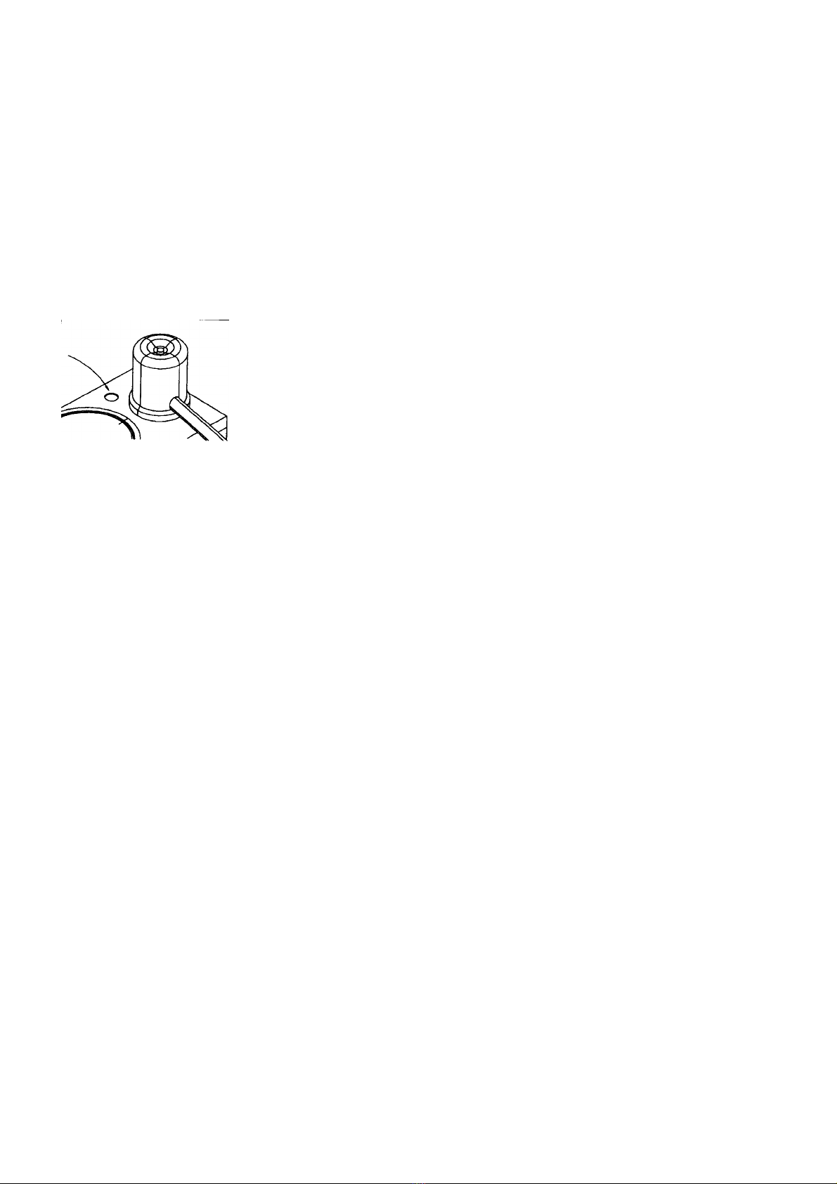
5. Take the plug out of the inlet on top of the
column. Pour the descaler solution in via
the opening next to the swivelarm using the
added funnel (fig 8).
6. Press the button for 1 l., 2,5 l. or 5 l. again.
7. Wait for about 3 to 5 minutes after the
acoustic signal to allow the solution to fulfil
its function.
8. After these minutes press the section button
for 4 l., 7,5 l. or 15 l.
9. When the indicator light of the button goes
out the container must be emptied. The

7
descaler solution can be disposed of
through the normal drain system.
10.Now press the selection button for 5 l., 10 l.
or 20 l. After the indicator light of the button
goes out, the container must be emptied
again.
11.Repeat instruction 10 once or twice, to be
sure that everything is rinsed thoroughly.
The filter unit can be rinsed separately.
12.Set the counter of the descaling indicator to
zero. (See chapter "To set the descaling
indication at zero" page 8)
Fig. 8
HOT WATER DISPENSER
Under normal operating circumstances, calcium
deposits will also appear in the hot water
dispenser. It must be regularly descaled in order
to function properly. When the hot water
dispenser has switched itself off, it is most
advisable to give it a really good descaling. Pay
special attention to removing the calcium
deposits from the two highest electrodes.
(Scrape them off with a small knife.) For
descaling purposes we advise RENEGITE, a
descaling agent which we have tested
ourselves. The following instructions are based
on the use of 100 gr of RENEGITE (read the
instructions on the packet as well).
The descaling procedure is as follows:
1. If the system is switched OFF and the water
is cold, drain off as much water as possible
via the hot water tap.
2. If the system is switched ON it must be
switched off and as much hot water as
possible drained. Cool the system by
pouring 3 litres of cold water into the
reservoir and draining it off again.
3. Dissolve 100 grms. descaling agent in ± 1
litre lukewarm water.
4. Pour the solution carefully into the hot water
reservoir.
5. Switch on the appliance again.
6. When the reservoir has been filled up to the
next to the highest electrode (see A, fig. 9),
wait ten minutes.
7. Meanwhile, draw off a cup of descaling
solution every minute from the usual hot
water taps (thereby giving the taps a good
descaling as well.)
8. Switch off the appliance once the ten
minutes is up and draw off as much solution
as possible via the usual tap.
9. Then pour ± 3 litres cold water into the
reservoir (to cool the system quickly).
10.To drain the reservoir quickly, the
instructions 11 through 14 can be followed.
11.At the front of the machine is a drain
situated (no. 12, fig. 1).
12.This drain can be opened by turning the key
(at the left hand side) a quarter of a turn
with a screwdriver or coin (the slot goes
from the vertical into the horizontal
position).
13.Drain the contents of the reservoir.
20.CAUTION ! Wear good protective gloves
when draining the descaling solution in this
way.
14.Close the drain by turning the slot in the
vertical position.
15.Now pour ± 5 litres of water into the
reservoir. Make sure it doesn't overflow.
16.Drain as much water as possible via the
usual hot water taps (thus rinsing the taps
as well).
17.Repeat operations 15 and 16 at least twice,
but now with ca. 4 l. water (the reservoir
may not overflow).
18.Switch on the water dispenser.
19.Before using the hot water for consumption,
it is advisable to rinse the taps well once
more by first drawing off another litre or so
of hot water via the hot water taps.
DRAIN
In case the drain is blocked, deblock it with the
aid of the cleaning spring. Therefore put the
spring into the drain and push it up and fro.
CAUTION !
- Leave the reservoir uncovered during the
entire descaling process.
- Prevent the descaling agent from touching
the top electrode.
- Due to the violent reaction which occurs
when the descaling agent comes into
contact with the calcium deposits, the water
may touch the topmost (safety) electrode,
thus switching off the system. In that case,
switch the system off manually using switch
(13.7, fig.1). Wait ca. 20 seconds and switch
the system on again in order to continue the
descaling process.

8
DESCALING INDICATION
The descaling indicator works with a counter that
keeps track of the amount of water that has
passed through the heater. At the moment a
predetermined amount has passed the red
indicator lamps start blinking.
This way the interval between descaling is not
determined by time but by a certain amount of
water and thus is more economic.
This amount depends on the hardness of the
water to be used. The harder the water the more
often the machine must be descaled.
The following table has to be considered:
Water Selection Water
hardness button amount
very hard 1,0 2,5 5 l ca. 280 l
hard (16 odH) 3,0 5,0 7,5 l ca. 560 l
medium 4,0 7,5 15,0 l ca. 1120 l
soft 5,0 10,0 20,0 l ca. 2240 l
To reset the counter, which has to be done
every time the coffee maker is descaled, and to
set the indicator, the following instructions are to
be performed:
Setting the descaling indicator
1. Press the stop button (no. 13.4, fig.1) and
keep it pressed until the four green indicator
lights in the selection buttons light up after
30 seconds. Till that moment one or more
short bleeps will sound every second.
2. Now the setting of the indicator can be
changed, when necessary, by pressing the
correct seletion button (see above table).
According to which selection button is
pressed, the red indicator lights blink every
second respectively 1, 2, 3 or 4 times.
(Once, pause, once, pause for 280 litres;
four times, pause, four times again for 2240
litres; similiary 2 and 3 for other settings.
To set the descaling indication at zero
1. Press the stop button shortly after having
set the indicator (the red and one green
indicator light will light up).
2. The counter is now reset by pressing the
selection button whose indicator is
illuminated.
3. When the stop button is now pressed briefly
one more time the machine can be used
normally again.
Note !
When during 30 seconds no adjustments are
made the control automatically goes bach to the
normal operation mode for coffee making.
The descaling indicator can be turned off
completely. To do this the stop button must be
pressed without any interruption for 1 minute.
During this time the short bleeps will sound, the
four green indicator light will light up and will go
out again. Before the indicator lights go out a
continuous acoustic signal will sound.
The indicator can be switched on again by
setting it in the way described above.
Fig. 9

9
COLUMN WITH COMPUTRONIC PANEL
OPERATION OF THE TIMER
Using the timer, up to four operational periods
per day can be set, within which the machine will
prepare coffee or tea. When a quantity is
programmed with the selector buttons outside
the set periods or blocks, the machine will only
begin to work when the next block is timed to
switch on. In this way, for example, the machine
can be set in the evening to prepare coffee or
tea the following morning.
The heating system for the coffee containers
fitted on the hot water column will also only be
switched on during the set blocks (the switch on
the container will have to be in the "on" position).
A selector switch (3, fig. 10) can be used to
switch off the timer manually. Operation of the
selector buttons can be blocked with the key-
operated switch (15, fig. 10), thus preventing
unauthorised alteration of the set quantities. This
does not block or protect the timer’s setting
facility.
In the following section, the operation of the
extra possibilities offered by the timer and the
key switch will be discussed in detail.
The timer
The timer blocks are set in ten-minute steps,
thus establishing the minimum interval and
duration times. The maximum block duration
time is 24 hours (from 00:00 h to 24:00 h);
overlapping blocks (including those which begin
and end at the same point in time) are seen as
one block. The block time settings are indicated
on the display above the adjustment knobs; ¾=
switch-on time, ¿= switch-off time 14 Cand D
(fig. 10).
The on/off status of a given block is indicated by
the visibility of the horizontal lines corresponding
to the lines between the red and blue adjustment
knobs (E, F, G & H, fig. 10).
Fig. 10
Letters and numbers used in fig. 10:
1.Rotary knob 12. Block 4 on
2.CL button 13. Block 4 off
3.Selector switch 14. Display
4.UHR button 15. Keyswitch
5.WT button A. Time
6.Block 1 on B. Day
7.Block 1 off C. Switching-on time
symbol
8.Block 2 on D. Switch-off time symbol
9.Block 2 of E. Block 1
10. Block 3 on F. Block 2
11. Block 3 off G. Block 3
H. Block 4
6 through 13 are programming buttons
E through H are switch symbols
The programming chart provided comes in
handy when setting the timer. An example of its
use is given (see fig. 11).
EXAMPLE
1st Block (cycle): from 07:00 to 12:00 except
Thursdays & Sundays.
2nd Block (cycle): from 14:00 to 19:00 except
Thursdays & Sundays.
Fig. 11

10
OPERATION
Setting the timer is done as follows:
1. Ensure the timer is connected to the mains
supply and set selector switch (3, fig. 10) to
the "timer" position ¥.
2. Delete: Push button CL (2, fig. 10), which
erases all settings, including those from
already set blocks.
3. Setting the current date: Push button WT
(5, fig. 10) and hold it in.
4. Rotate the rotary knob (1, fig. 10) in the +
direction until the current day appears on
the display with arrow ¾(B, fig. 10). Then
release button WT 5.
5. Setting the current time: Push button UHR
(4, fig. 10) and hold it in.
6. Rotate the rotary knob in the +or -direction
until the correct time appears on the display
(A, fig. 10). Then release button UHR 4.
The time is now set.
7. Push button WT 5 and hold it in.
8. Rotate the rotary knob in the +or -direction
until the weekday which is to be set
appears on the display with the arrow ¾(B,
fig. 10). Then release button WT 5. (If no
further settings are to be made and you
only wish to operate the timer as a clock,
briefly push button UHR 4 once more. The
default setting of pre-programmed clocks
will now be activated. The default setting is
used for Mon through Sun and is identical
for all 4 blocks: Switch-on time: 06.00;
Switch-off time: 22.00 hours.)
Follow instructions 14 or 15 to change the
default setting.
Follow instruction 9to set the timer blocks.
9. Set timer blocks, start time: Push the red
button for the block to be set (6, 8, 10, or
12, fig. 10) and hold it in.
10.Rotate the rotary knob until the desired
block starting time appears on the display
A. Then release the red button.
11.Set timer blocks, end time: Now push the
blue button for the block to be set (7, 9, 11
or 13, fig. 10) and hold it in.
12.Rotate the rotary knob until the desired
block finishing time appears on the display
A. Then release the blue button.
13.To set another block on the same day,
repeat instructions 9 through 12; to set a
block on another day, follow instructions 7
through 12.
14.To remove the set blocks, even the
pre-programmed ones: Repeat
instructions 7 or 9 through 12. However, at
instructions 10 and 12, turn the rotary knob
towards the -until - - - - appears on the
display.
15.To change a pre-programmed block, follow
instructions 7 through 12.
16.Once all blocks have been set, push button
UHR 4 once briefly; the timer display will
now indicate the current date and time and
the set blocks will be activated.
If the selector switch 3is set at position ¥after
programming, the machine will only operate
within the preset blocks.
If the selector switch is set at position I, the
machine can be operated at any time.
In position 0, the machine is permanently
blocked.
The diagonal lines Ethrough Hbetween on and
off arrows Cand Dshow which block is currently
activated.
NOTE !
When the power of the timer is blocked more
than ca. two days, the setting will be cancelled.
The timer must be set again.
The key switch (15, fig. 10)
To prevent operation of the selector buttons,
proceed as follows:
1. Insert the key in the lock.
2. To lock the selector buttons, turn the key
until it is vertical.
3. To unlock the switches, return the key to the
horizontal position.
4. Remove the key from the lock.
(SUBJECT TO MODIFICATION)

VHH
Coffee brewing machines
© 10-1998
This manual suits for next models
2
Table of contents
Other VHH Coffee Maker manuals
Popular Coffee Maker manuals by other brands

Adler Europe
Adler Europe AD 4408 user manual

Jura
Jura Giga X3 Professional Instructions for use

Continental Refrigerator
Continental Refrigerator Elite CELT-CE005 user manual

Gevi
Gevi GECME022-U Instruction booklet

Holstein Housewares
Holstein Housewares HH-09101009B manual

Nespresso
Nespresso Prodigio TURMIX instruction manual