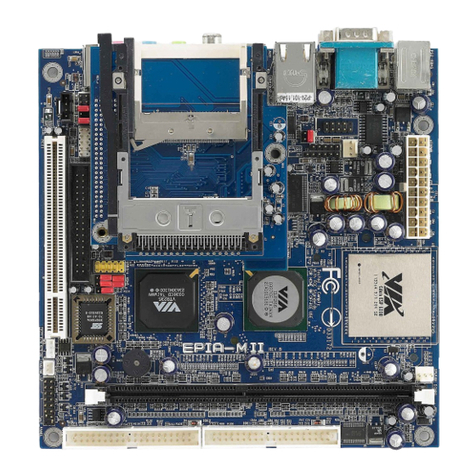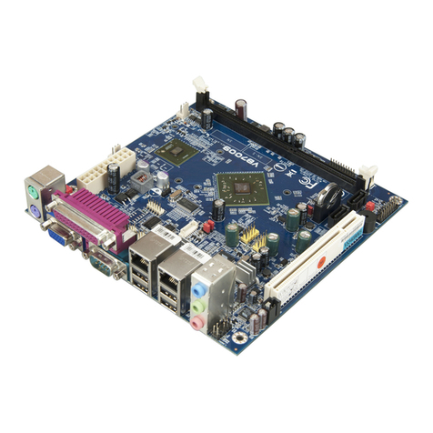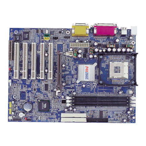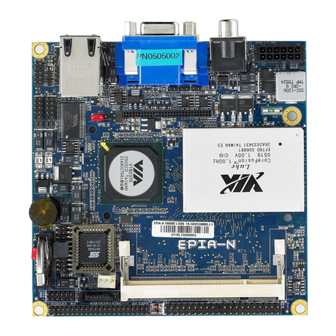
VIA EPIA-M930 User Manual
viii
List of Figures
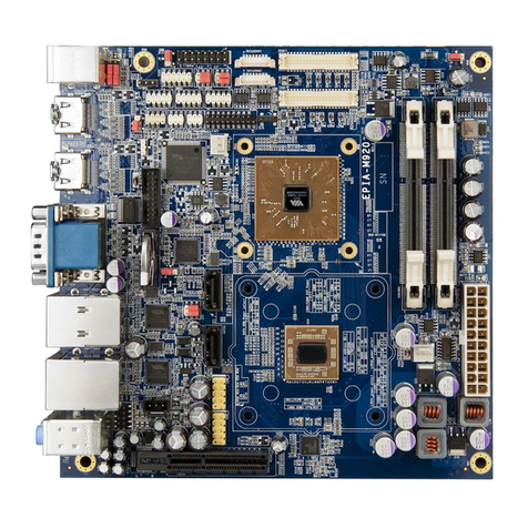
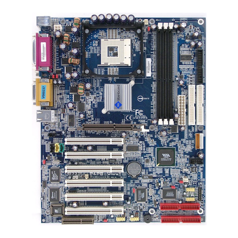
Figure 01: VIA EPIA-M930 board layout (top view) ............................................................................................... 3
Figure 02: Mounng holes and dimensions of the VIA EPIA-M930....................................................................... 5
Figure 03: External I/O port dimensions of the VIA EPIA-M930............................................................................ 5
Figure 04: Height distribuon of the VIA EPIA-M930............................................................................................ 6
Figure 05: Back panel I/O ports ............................................................................................................................. 7
Figure 06: HDMI® port diagram............................................................................................................................. 7
Figure 07: COM port diagram................................................................................................................................ 8
Figure 08: Gigabit Ethernet port diagram.............................................................................................................. 9
Figure 09: Audio jack receptacle stack ................................................................................................................ 10
Figure 10: USB 3.0 port diagram.......................................................................................................................... 10
Figure 11: USB 2.0 port diagram.......................................................................................................................... 11
Figure 12: DC-in jack specicaon diagram......................................................................................................... 11
Figure 13: DC-in jack diagram.............................................................................................................................. 11
Figure 14: ATX power connector diagram ........................................................................................................... 12
Figure 15: LVDS panel connectors diagram ......................................................................................................... 12
Figure 16: Backlight control connectors diagram ................................................................................................ 13
Figure 17: Digital I/O pin header diagram ........................................................................................................... 14
Figure 18: Front panel pin header diagram ......................................................................................................... 15
Figure 19: CPU fan connector diagram................................................................................................................ 16
Figure 20: SATA connector diagram..................................................................................................................... 16
Figure 21: USB 2.0 pin header diagram ............................................................................................................... 17
Figure 22: COM pin headers diagram.................................................................................................................. 18
Figure 23: Front audio pin header....................................................................................................................... 18
Figure 24: SPI pin header diagram....................................................................................................................... 19
Figure 25: CMOS baery slot diagram................................................................................................................. 20
Figure 26: Jumper sengs example .................................................................................................................... 21
Figure 27: Clear CMOS jumper diagram .............................................................................................................. 21
Figure 28: COM1 and COM2 voltage jumper diagram......................................................................................... 22
Figure 29: COM3 and COM4 voltage jumper diagram......................................................................................... 23
Figure 30: LVDS1 and LVDS2 power jumpers diagrams ....................................................................................... 24
Figure 31: DDR4 memory slot diagram ............................................................................................................... 25
Figure 32: Inserng the memory module............................................................................................................ 25
Figure 33: Locking the memory module.............................................................................................................. 26
Figure 34: Disengaging the locking clips.............................................................................................................. 26
Figure 35: Removing the memory module.......................................................................................................... 26
Figure 36: PCI Express slot diagram..................................................................................................................... 27
Figure 37: M.2 slots diagram............................................................................................................................... 27
Figure 38: SIM card slot diagram......................................................................................................................... 28
Figure 39: Suggested minimum chassis dimensions............................................................................................ 29
Figure 40: Suggested minimum internal chassis ceiling height ........................................................................... 30
Figure 41: Illustraon of the Main menu screen ................................................................................................. 32
Figure 42: Illustraon of the Advanced Sengs screen ...................................................................................... 33
Figure 43: Illustraon of the CPU Conguraon screen ...................................................................................... 34
Figure 44: Illustraon of the Hardware Health Monitor screen .......................................................................... 34
Figure 45: Illustraon of the Hardware Monitor screen...................................................................................... 35
Figure 46: Illustraon of the S5 RTC Wake Seng screen ................................................................................... 35
Figure 47: Illustraon of the SIO Common Seng screen................................................................................... 36
Figure 48: Illustraon of the SIO Conguraon screen ....................................................................................... 36
Figure 49: Illustraon of the Serial Port Conguraon screen ............................................................................ 37
Figure 50: Illustraon of the Serial Port Conguraon screen ............................................................................ 38
Figure 51: Illustraon of the Wake-up Conguraon screen............................................................................... 38
Figure 52: Illustraon of the Realtek PCIe GBE Family Controller screen............................................................ 39
Figure 53: Illustraon of the User Password Management screen...................................................................... 40
Figure 54: Illustraon of the Chipset Sengs screen .......................................................................................... 41
Figure 55: Illustraon of the System Agent (SA) Conguraon screen................................................................ 42
Figure 56: Illustraon of the Memory Conguraon screen............................................................................... 42
