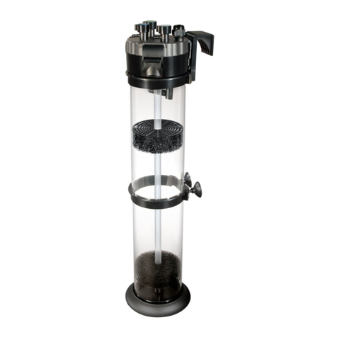
ViaAqua UTC-3200 Installation and operation manual

WARNING!
Buyer/user assumes all responsibility for
safety and proper use not in accordance
with the directions and safety labels.
UTC-3200, UTC-3200UV, UTC-3400 and UTC-3400UV

1
Features
• DESIGNED TO SUPPORT AQUATIC LIFE AND
ENGINEERED FOR THE HOBBYIST.
• Quiet, Energy Efficient.
• Easty to set-up, install and maintain.
• Modular design for variety filter medias.
• UV model equipped with UV Sterilizer.
• Standard UTC model equipped with priming plunger
• Distinctively Superior Filtering System.
• High Performance External Filter.
• Heavy Duty Latches.
• Water Tight Seal.
• Built-in Handle, for Easy Carrying During Maintenance.
• Filtering Baskets, with Separate Grids for Various Filtering
Media Allowing Efficient Four Step Filtration:
1. Mechanical
2. Biological
3. Chemical
4. UV Sterilizer (for Model with UV Sterilizer only)
• Durable Ceramic Shaft for Freshwater and
Marine aquariums.
• Oil Free Motor.
• Anti-Slip Rubber Feet.
Specifications
Technical Data
Model GPH/LPH Power
Consumption
Filter
Volume
Aquarium Size
UTC-600
194/740 13 Watts
1.26 Gal. 10 -40 Gal.
UTC-800 1.58 Gal. 15 -60 Gal.
UTC-1000
355/1350 28 Watts
2.5 Gal. 20 -70 Gal.
UTC-1200 3.16 Gal. 20 -90 Gal.
UTC-3200
581/2200
55 Watts
4.74 Gal. 80-210 Gal.
UTC-3200UV 63Watts
UTC-3400 55 Watts
5.79 Gal. 80-240 Gal.
UTC-3400UV 63Watts
Dimensions
Model Length (in.) Width (in.) Height (in.) UPC#
0069037
UTC-600 8.8 8.8 13.6 2944 4
UTC-800 8.8 8.8 15.6 2945 1
UTC-1000 10.4 10.4 16 2946 8
UTC-1200 10.4 10.4 18.8 2947 5
UTC-3200 13.2 13.2 18.8 2948 2
UTC-3200UV 13.2 13.2 18.8 2949 9
UTC-3400 13.2 13.2 21.6 2950 5
UTC-3400UV 13.2 13.2 21.6 2951 2

2 3
Parts List
of Standard UTC Model
1. Valve lever
2. Valve and tap connector
3. Pump lid
4. Latches
5. Ceramic shaft
6. Impeller
7. Impeller cover
8. Filter sponge coarse
9. Filter wool pad fine
10. Retractable handle
11. Media container
12. Filter container
13. Priming plunger
14. Priming tube
15. Pump lid intake tube
16. Rubber seal
17. Discharge pipe
18. Intake elbow
19. UV intake slot
20. UV PL light bulb 5 watts
21. Quartz sleeve and
reaction chamber
Part List
of UV Model
4
10
20
21
1
2
3
6
7
8
11
9
10
12
4
5
14
15
16
17
18
19
5
7
6
5
7
6
1
2
3
6
7
11
9
10
8
12
5
13
10 19
16
17
13

4 5
Warning and Safeguards
Do not deviate from the following Warning and Safeguards.
Before installation of a ViaAqua®Modular Canister Filter, read and follow these
important Warning and Safeguards.
• Do not operate ViaAqua®Modular Canister Filter without water. Doing so can cause
permanent damage to the canister filter.
• Carefully check the canister filter after installation to ensure that the canister filter and the
tubing connecting the canister to the aquarium are not wet.
• Prior to maintenance on any electrical aquarium appliance or maintenance to the
aquarium, you must disconnect all electrical aquarium devices.
• Use this product for its intended use only.
• Verify that tubing and the canister filter are not in contact with moving parts or hot parts
such as heaters.
• Routine maintenance is required to ensure the maximum performance and the longevity
of the ViaAqua®Modular Canister Filter. See maintenance guidelines.
• The use of a surge suppressor is strongly recommended.
• Never yank or pull the cord from the electrical outlet.
• Do not operate if the plug or wire is damaged.
Warning! For all Models with
a UV sterilizer
• Do not look at UV bulb when lit. Exposure to
ultra-violet
light can damage eyes and skin.
• Do not open the filter when the pump and
filter are operating.
Parts List
This product may contain chemicals known to the state of California to
cause cancer and or birth defects or other reproductive harm. Wash your
hand after handling this product.
It is your sole responsibilities to verify that the plug and the receptacle are
clean and free of moisture and salt build up at all times. The receptacle
must be free of water, salt, calcium, magnesium and dust. Failure to do
so can cause fire, damage to property, permanent damage to the product
and personal injury not limited to loss of life.
Do not plug into extension cord/power strip.
A drip loop must be used when plugging all electrical aquarium
devices. A drip loop is that part of the cord hanging below the
receptacle.
The national code requires that a GFCI (Ground fault circuit
interrupter) be used in the branch circuit supplying all power to
water pumps and electrical aquarium equipment. If you do not
have a GFCI, have an electrician install one prior to operating any
aquarium component.
22. Tubing
23. Pump lid O-ring
24. Suction cups
25. U-shape intake pipe
26. Priming cap
27. Surface skimmer
28. Extensions
29. Couplers
30. Intake strainer
31. U-shape return pipe
32. Output elbow
33. Spray bars
34. Spray bar cap
Drip
Loop
GFCI
ONLY
Drip
Loop
GFCI
ONLY
Tubing
Pump lid O-ring
U-shape return pipe
Suction cups
Surface
skimmer
Extension
Couplers
Intake strainer
Spray bars
Spray bar cap
Output elbows
22
23
31
24
27
18
29
30
33
34
32
Priming cap26
U-shape intake pipe25

6 7
Installation
1. Remove the pump lid
A. Flip out all 4 latches. Two on the canister and two on the pump lid.
B. Lift the pump lid off of the canister.
2. Install pump lid O-ring
Note: The O-ring has been pretreated with silicone
lubricant to ensure a proper seal.
A. Remove O-ring from
the sealed bag. Place
O-ring in the groove in
the pump lid.
B. Verify that the O-ring is
not soiled.
3. Take out the media
containerstollthemwithltermedia
Note: The media containers will have to be
replaced in the order they were removed.
A. Take out the media containers one at a time.
B. The retractable handles of the media containers can be pulled out in an upward
direction for removal.
C. Recommended media below for three stage filters:
Top:Filter pads (filter sponge coarse and filter wool pad fine).
Middle: Carbon or resin filtering media. Media needs to be placed in a media bag.
Bottom: Biological media.
4.Replacelledmediacontainers:
Note: Media containers must be placed back in the
order they were removed
A. Align the media containers guide arrow with the arrow
on the brim of the canister.
B. Place the media containers back into the canister.
Start with media container #3.
C. Position container #3 firmly within the support frames
on the bottom of the canister.
D. Stack the remaining containers.
5. Replace the pump lid:
A. Check to make sure the pump lid O-ring is not soiled
and that it is in the proper groove.
B. Use silicone lubricant is recommended to ensure a
good seal. Add silicone lubricant directly to the O-ring.
C. Attach the pump lid intake tube to the impeller cover.
D. Place media container gasket onto media container #1
discharge pipe.
E. Insert the pump lid intake tube into the discharge pipe
until the pump lid comes in contact with the canister.
F. Press directly down on the top of the pump lid. The
pump lid must be flush with the canister filter prior to
securing. Latch and secure.
6. Connect the valve and tubing
tap connectors to pump lid:
A. Position the valve lever so that it is in a
vertical position.Hold the valve and tubing
tap connector so that you can read the “out”
and “in” and press directly into the pump lid.
B. Press down valve lever towards pump lid
to secure.
O-Rings
Standard UTC Model UV Model
O-Rings
1
2
3
1
2
3
Standard UTC model ONLY

8 9
7.Positioncanisterlter
Place the canister filter into the cabinet or floor beneath the aquarium. Surface needs to
be level.
8. Intake and output tube set-up
Intake tube set up:
Note: If you use the surface skimmer the water level must stay the same once
the surface skimmer is set. Failure to do so will cause air bubbles to enter the
canister and the unit may loose prime.
A. Open the bag of Intake tube parts.
B. Connect the surface skimmer to the U-shape intake pipe. Surface skimmer water
level should be ¼”to 3
/
8”from the bottom of the slots.
C. Connect the extension to the bottom of the surface skimmer.
D. Connect the intake strainer to the extension.
E. Connect flexible tubing and secure with the lock nut.
F. Secure the intake tube with suction cups so that the intake tube is vertical.
G.Verify that the intake strainer is a min. of 2”from the substrate.
Output tube set up:
A. Open bag of output parts.
B. Connect U-shape return pipe to output elbow.
C. Connect output elbow so that the spray bar is just below the water level.
D. Connect flexible tubing and secure with the lock nut.
E. Secure spray bar with suction cups.
9. Determine the length of tubing
Note: It is very important not to cut the tubing too short. If the tubing is cut to
short and creates tension on the valves the unit will leak. Additionally, leaving the
tubing too long may prevent the unit
from priming. There cannot be any kinks
in the tubing.
Now determine the length of tubing required
to attach the Inlet and Output pipes to the
aquarium. Add an extra 6” of tubing to the
length of the tube to avoid cutting tubing to
short. The tubing needs to be installed so
that there are not any kinks in the lines.
10.Startingyourlter:
Note: There must be water in the
aquarium to start.
A. Fill canister with water. 1
/ 3full.
B. Place the valve lever in the “off” position.
C. Now unscrew the priming cap on the
intake prime/ U tube.
D. Using a small funnel fill the intake tube
until full.
E. Turn valve lever to the “on” position. This
will start a siphon and air bubles and/or
air will exit the spray bar.
F. Once the canister is filled and the
output tube has water, Plug unit into a
GFCI outlet.
G.If it does not start, press the priming
plunger several times and restart unit.
Units only without a UV.
H. When starting the filter afther routine
maintenance, canister can be placed
without water. Replace valve and
tubing tap connector. Once valve is
sealed in place a siphon will start
filling the canister. Once all air is
forced out of the unit, canister, and
tubes are filled, restart unit.
11.Oncethelterisrunning
double check all the
ttingsandsealstoverify
there are not any leaks.
Min. 2 in.
ONOFF
Min. 10cm
Max.
200cm

10 11
Maintenance
To ensure optimum filtering and to maintain full water flow regular maintenance
is required. It is recommended to clean or change filtering media at least every
4 weeks. Decreased water flow is a sign of clogged filter media.
1. Unplug the unit from the GFCI outlet. Prior to maintenance on any electrical aquarium
appliance or maintenance to the aquarium, you must disconnect all electrical
aquarium devices.
2. Remove valve/tap connectors from pump lid.
3. If cover is removed without removing valve/tap connectors water will siphon onto
the floor..
4. Remove the canister and place in an area suitable for maintanence.
5. Flip out each of the four lid housing clips and release the pump motor housing. The
motor housing cannot be lifted off the canister.
6. Remove the filter strainer and remove the media containers one at a time using the
handle. Note the media containers need to be replaced in the same order removed.
7. Replace filter pads and medians.
8. Clean the canister and impeller/impeller housing.
A. Remove the impeller cover.
B. Remove the impeller and shaft, clean with water. With a small brush
clean the inside of the impeller well.
C. Do not clean with soap.
D. Reassemble.
9. Apply a small amount of silicone sealant to the gasket/o-ring to insure a good seal.
10. Install according to the directions for installation.
Note: When starting the filter afther routine maintenance, canister can be placed
without water. Replace valve and tubing tap connector. Once valve is sealed in place
a siphon will start filling the canister. Once all air is forced out of the unit, canister,
and tubes are filled, restart unit.
Trouble Shooting
Problem: Canister will not prime or pump water
Solutions:
1. There is no water in the aquarium.
2. The impeller needs to be cleaned. Verify that the impeller spins freely on the shaft.
3. Air is in the impeller well. Unplug and tilt the unit until air evacuates and restart.
4. The intake and the output are switched on the motor housing, connect the intake to
the “IN” and the output to the “OUT” on the motor housing.
5. There is not any water in the intake tube. Fill intake tube by removing the
priming cap.
6. The spray bar endcap is not at the end of the spray bar and is blocking
the water flow.
Problem: Excess noise
Solutions:
1. It is not uncommon to have a rattling noise during set-up and while the unit is trying to
remove the air in the canister.
2. The intake of the canister filter is sucking in air. Relocate all air stones and air
powered ornaments to an area of the aquarium away from the intake of
the canister filter.
3. Impeller and the impeller well needs to be cleaned.
4. Canister needs to be cleaned.
5. Shaft and/or impeller is damaged and needs to be replaced.
Problem:Slowwaterow
Solutions:
1. Medians are to tightly packed in the median containers.
2. The impeller and impeller well needs to be cleaned.
3. Tubing needs to be cleaned.
4. Canister needs to be cleaned and medians changed.
5. The intake strainer is clogged.
Problem: Leaking water
Solutions:
1. Tubing is not properly installed. Verify that the collar on the valve and tubing tap
connectors are over the tubing. A clean-cut tube is essential for a good seal.
2. A small amount of silicone lubricant needs to be added to the gasket/O-ring.
3. The extra replacement O-rings where placed in the incorrect spot. Remove
replacement O-ring and reinstall.
TECHNICAL SERVICE DEPARTMENT
Monday to Friday 9 am - 5 pm PST
(805) 383-3566 ext. 102

12 13
Limited Warranty
Commodity Axis, Inc.®warrants that the ViaAqua®Modular Canister Filter is free
from defects for a period of one year from the initial date of purchase shown on the original
cash register receipt. Commodity Axis, Inc.®disclaims all other warranties, express or
implied, including but not limited to any implied warranties of merchantability and/or fitness
for a particular purpose. Although this limited warranty gives you specific rights, you may
have other rights which vary from state to state. This warranty is void if the failure is due
to misuse, tampering, negligence, abuse, accident and/or submersion, a failure to properly
install, maintain, clean, prefilter, reassemble, and/or failure to use the ViaAqua®Pressure
Pond Filter with a Ground Fault Circuit Interrupter (GFCI).
Consumer Remedies
Commodity Axis, Inc.®entire liability and your sole and exclusive remedy shall be
either repair or replacement of the ViaAqua®Modular Canister Filter only if you return the
defective unit directly to Commodity Axis, Inc.®with the original receipt in its original box
along with twenty five dollars ($25.00) for shipping and handling. Do not send the ViaAqua®
Modular Canister Filter by insured mail. You may send your returns or replacements by UPS
requiring a signature upon arrival. Any replaced unit will be warranted for the remaining time
of the original warranty period. In no event shall any shipping charges be reimbursed. In
no event will Commodity Axis, Inc.®be liable for any consequential or incidental damages,
including but not limited to, lost sea life, personal injury, property damage, equipment damage,
lost profits, lost wages, lost savings, lost income, etc., arising out of the use of the ViaAqua®
Modular Canister Filter . Some states do not allow for the limitation or exclusion of liability for
incidental or consequential damages, so the above exclusion may not apply to you.
Returns
Please contact our service center at (888) 838-3882 or fax (888) 989-0878 to
arrange repair and/or replacement. Please allow 4-6 weeks for all returns. Commodity Axis,
Inc.®cannot ship nor respond to a P.O. Box address.
Warranty Card
Please go to our website, to download Warranty Card.
http://www.viaaquaoceanpure.com/main/resources.html
Fill out this warranty card and mail it with PROOF OF PURCHASE within 15 days of purchase
Replacement Parts
Part Number Description
2 Valve and tap connectors
5-6 3200 Impeller and ceramic shaft
5-6 3400 Impeller and ceramic shaft
10 Filter sponge coarse. 2 pk.
11 Fitler wool pad fine. 2pk.
15 Rubber seal
19 Replacement UV bulb 5 watts
20 Quartz sleeve and reaction chamber
21 Tubing set 2 x 78”
22 Pump lid O-ring
23 Suction cups. 6 pk.
24 U-shape intake pipe
24 & 26 U-shape intake pipe with surface skimmer
30 U-shape return pipe
32 Spray bar kit

Commodity Axis, Inc.®is also a manufacture of
ViaAqua®Acro-Cal™ Reactor, ViaAqua®Poly Reactor™,
ViaAqua®Oceanpure™Salt, ViaAqua®Glass Heater, ViaAqua®Titanium Heater,
ViaAqua®MillionAir™Air Pump, ViaAqua®Water Pumps, ViaAqua®Glass Aquariums
and Helios®Lighting Systems.
© 2011 Commodity Axis, Inc.®
Specifications are subject to change without notice
Bringing Products to Life
www.ViaAquaOceanpure.com
This manual suits for next models
7
Table of contents
Other ViaAqua Water Filtration System manuals
Popular Water Filtration System manuals by other brands

Filtration Group
Filtration Group Pi 21430 Translation of the original instructions

Innowater
Innowater SMC50 manual

Eurotech
Eurotech SKM 1 user manual

JRC
JRC NSVS1147 manual

East Midlands Water Company
East Midlands Water Company Zip user manual

Thermo Scientific
Thermo Scientific Smart2Pure Pro Installation and operation

Clean Water Systems
Clean Water Systems Pro-OX 5700-E Installation & start?up guide

Pura Vida
Pura Vida PSII-48PV installation instructions

OZTTER
OZTTER RL8 instruction manual

Pond Boss
Pond Boss FUV9 manual

Ispring
Ispring RCC7 Installation instructions & owner's manual

ABB
ABB PQFS Installation, operation and maintenance instructions