ViaLite ViaLiteHD User manual

PULSE POWER &MEASUREMENT LTD
2
Instrument Care and Safety Information
Please read the whole of this section before using your ViaLiteHD product. It contains important safety
information and will enable you to get the most out of your Fibre Optic Link.
Electrical Safety
The ViaLiteHD rack chassis is a Safety Class 1 product (having metal chassis directly connected to earth via the
power supply cable).
When operating the equipment note the following precautions:
Hazardous voltages exist within the equipment. There are no user serviceable parts inside; the covers should
only be removed by a qualified technician.
There are no user replaceable fuses in the rack chassis mounted equipment. Replacement should only be
carried out by a PPM technician.
The rack chassis earth stud SHOULD be connected to the safety earth.
When using a 2 pin power supply cable the rack chassis earth stud MUST be connected to the safety earth.
The ViaLiteHD Power Supply Modules do not have an isolating switch on the mains voltage inlet. For this
reason, the ViaLiteHD Rack Chassis must be installed within easy reach of a clearly labelled dual pole mains
isolation switch, which supplies the equipment.
ESD Precautions The ViaLiteHD RF Fibre Optic Link is equipped with high frequency active electronics, without the correct handing they
will be susceptible to damage.
Precautions for handling electro-static sensitive devices should be observed when handling all ViaLiteHD modules.
Technicians should ensure that they use effective personal grounding (i.e. ESD wrist strap etc.) when servicing the
equipment. Any equipment or tools used should be grounded to prevent static charge build-up. Good practice should
be observed at all times for reference see relevant standards.
EN 61340-5-1, “Protection of Electronic Devices from Electrostatic Phenomena – General Requirements”
Optical Safety The ViaLiteHD RF Fibre Optic Transmitters, Dual Transmitters and Transceivers contain optical sources (usually
laser diodes) operating at nominal wavelengths of 1270nm to 1610nm.
These devices are rated as EN60825-1 as CLASS 1 radiation emitting devices. A class 1 laser is safe under all
conditions of normal use.
When operating the equipment note the following precautions:
Never look into the end of an optical fibre directly or by reflection either with the naked eye or through an optical
instrument.
Never leave equipment with radiating bare fibres –always cap the connectors.
Do not remove equipment external covers when operating.
Hot surface The ViaLiteHD Summary alarm module may have hot surfaces when operating under fulll load. The hot surfaces are
not accessible when fitted in an approved rack chassis installation.
Suitable precaution should be taken when handling this device.
Allow to cool for 10 minutes
Do not touch metallic surfaces or printed circuit board when hot.
When handling, hold front panel and handle only.

PULSE POWER &MEASUREMENT LTD
3
TABLE OF CONTENTS
1INTRODUCTION.................................................................................................................................................................................4
Internal architecture 4
Typical deployment 5
ViaLiteHD and ViaLite Classic compatibility 5
2SUMMARY ALARM MODULE, PHYSICAL INTERFACES..................................................................................................................6
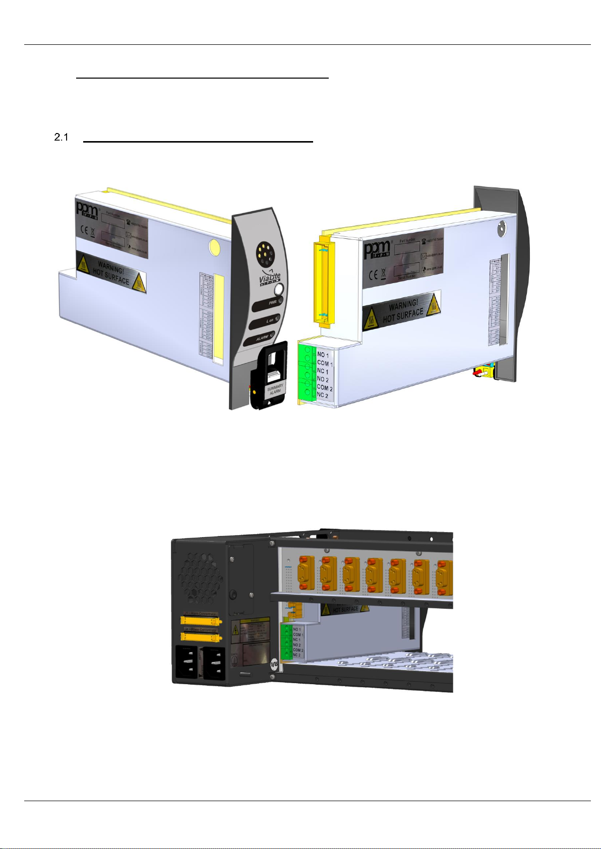
Module operation, 7HP standard plug-in module 6
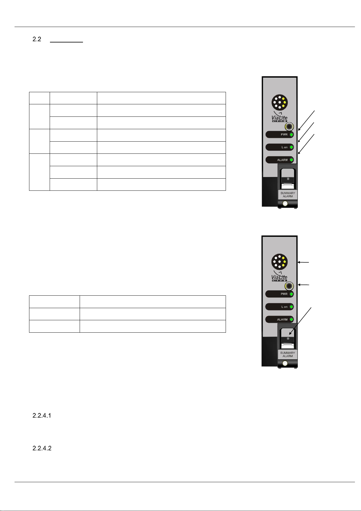
Front panel 7
2.2.1 Front panel, visual indicators 7
2.2.2 Front panel, reset switch 7
2.2.3 Front panel, buzzer 7
2.2.4 Front panel, acknowledge switch 7
Front panel, acknowledge switch, slot alarm active, with I2C response, fail module..........................7
Front panel, acknowledge switch, slot alarm active, with no I2C response, removed module............7
Front panel, acknowledge switch, slot alarm inactive, with I2C response, replaced module..............8
Front panel, acknowledge switch, slot alarm inactive, with no I2C response, fail module..................8
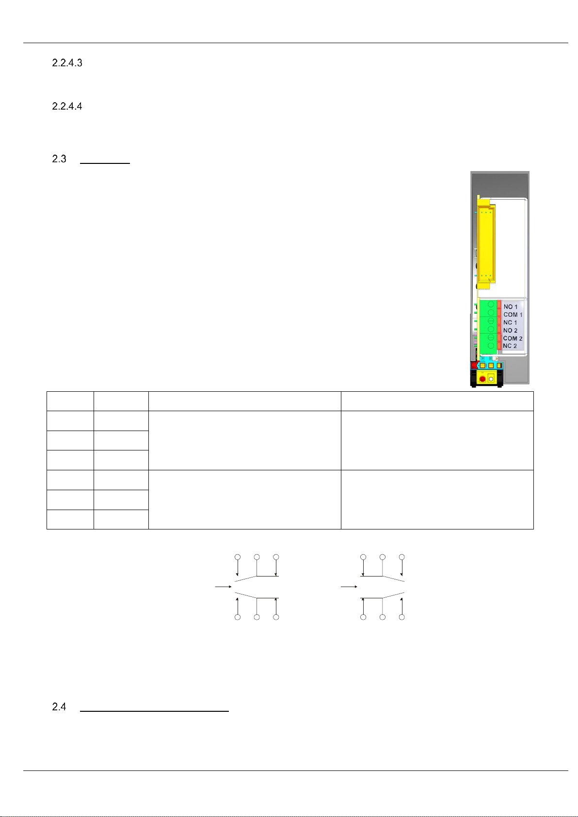
Rear panel 8
2.3.1 Rear panel, module rear connections 8
2.3.2 Rear panel, backplane relay connection 8
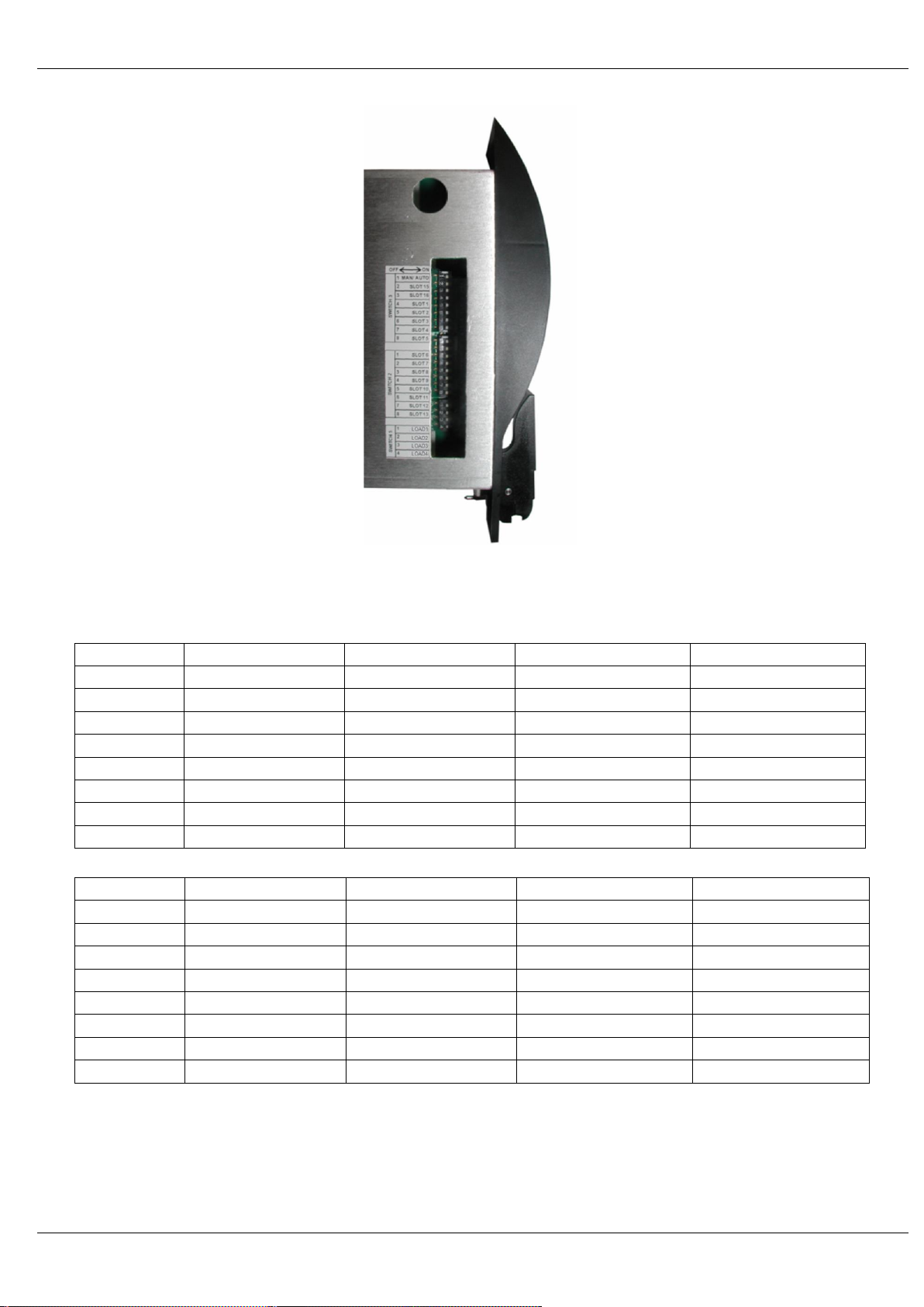
User configuration DIP switches 8
2.4.1 User configuration DIP switches, alarm masking SW2 and SW3 9
2.4.2 User configuration DIP switches, load resistors SW5 10
3SETTING UP THE SUMMARY ALARM MODULE ............................................................................................................................11
Default configuration 11
Setting the Alarm masking, manual mode 11
Setting the Alarm masking, automatic mode 11
Setting the load DIP switches 11
Connecting to the rear relay connections 11
4SYSTEM INTEGRATION..................................................................................................................................................................12
Initial set up equipment 12
Site requirements 12
5MECHANICAL DIMENSIONS...........................................................................................................................................................13
6PART NUMBERING..........................................................................................................................................................................14
7TECHNICAL SPECIFICATIONS .......................................................................................................................................................15
8MAINTENANCE AND FAULT-FINDING GUIDE................................................................................................................................16
9GLOSSARY......................................................................................................................................................................................17
10 PRODUCT WARRANTY...................................................................................................................................................................18
11 FCC APPROVAL ..............................................................................................................................................................................19

PULSE POWER &MEASUREMENT LTD
4
1 Introduction
The ViaLiteHD Summary alarm module is used to monitor ViaLiteHD equipment fitted in the same rack. It is able to report alarms by front
panel visual indication, audio alarm and by status of it’s on board relays. There are two form C relays, both accessible at the rear of the
module; one relay is also routed to the cabinet backplane.
The summary alarm module maybe configured, so that it’s on board processor automatically senses and alarm only active module; or it may
be configured via manual DIP switches both monitoring and controlling modules
The module has an on board resistive load, this can be configured via DIP switches to ensure the power supplies meet their minimum load
requirement. See your ViaLiteHD Rack Handbook for more details.
Internal architecture
Key features are:
The CPU monitors all rack alarm outputs
Compatible with either 1U or 3U rack
The CPU controls all module outputs
The module fits in ViaLiteHD rack chassis 7HP slot,
oIn a 1U HRK1 rack it fits in slot 3
oIn a 3U HRK3 rack it fits in slot 14
DIP switches available for manual alarm screening, slots 1-13 and slots 15,16
I2C bus is used at start up to monitor active slots for automatic alarm masking
Two dry contact relays, both accessible on module rear connector, one wired in parallel to the rack chassis connector
Front panel LED indication of rack summary status.
Front panel buzzer, giving audio alarm when fault is active
Front panel ACKNOWLEDGE switch
Different indication for active ALARM and acknowledged ALARM
The DC input power feed (+12 volts) is protected by a set resetable fuse.
The internal 5V is generated by linear regulator
PSU
DIP
switch
bank
CPU
Load
4 * 3W
Mute
switch
Buzzer
LEDs I2C
Relay1
Relay2
Alarm
inputs
NO
COM
NC
NO
COM
NC
NO
COM
NC
MS_X
I2C
15 Alarm_X
13
Backplane
Module rear
Backplane
Front panel

PULSE POWER &MEASUREMENT LTD
5
Typical deployment
The Summary alarm module is typically deployed as part of a 3U rack chassis based equipment solution. It can however be fitted in a range
of other equipment.
When fitted in an HRK3 rack chassis it must be fitted in slot 14, this is the only slot to have communication with all other slots.
ViaLiteHD and ViaLite Classic compatibility
The ViaLiteHD summary alarm module will not control or monitor ViaLite Classic equipment.
Its dry contact relay circuits will be compatible with circuits used on previous ViaLite Classic equipment.

PULSE POWER &MEASUREMENT LTD
6
2 Summary alarm module, physical interfaces
This section describes the connections between your ViaLiteHD modules and the Summary alarm module. There is no need to install any
interface cables between summary alarm module and connected modules, as these are all connected via the rack chassis backplane.
Please read fully all relevant documents for information on installing your ViaLiteHD equipment before commissioning your system.
Module operation, 7HP standard plug-in module
All ViaLiteHD plug-in modules are hot-swappable, so it is not necessary to power-down the rack chassis before inserting a module. All
electrical connectors are retained by the module. So it is necessary to either disconnect any cables or have a sufficiently long service loop.
To install a 7HP Standard module
Push the release button of the module handle down and simultaneously pull the top of the handle forwards.
Align the module upright and perpendicular to the front face of the rack chassis so that the PCB slides into the “crow’s feet” card guides
top and bottom.
Gently push the module down its guide, applying pressure via the handle, you may also apply pressure between the LED and buzzer.
As the module is fully mated the top of the handle should snap back and lock in position.
The pawls of the handle should be fully engaged in the matching slots.
If power is applied to the rack chassis the module power LED should light as soon as the module is fully inserted
Connect any interface cables
To remove a 7HP Standard module
Disconnect any cables if necessary
Push the release button of the module handle down and simultaneously pull the top of the handle forwards.
Apply pressure via the handle and gently withdraw the module from the rack chassis.

PULSE POWER &MEASUREMENT LTD
7
Front panel
2.2.1 Front panel, visual indicators
The summary alarm plug-in module has three front panel LEDs for indication of the state of the module. The following table shows the
operation of the front panel LEDs which are dependent on module type.
Colour
Status
LED1
GREEN
Normal
No light
No power
LED2
GREEN
LOAD ON (Any load resistor active)
No light
LOAD OFF
LED3
GREEN
Normal
Solid RED
ALARM, acknowledged
Flashing RED
ALARM, active
2.2.2 Front panel, reset switch
The hard reset switch is accessible via a small hole behind the handle. Under all normal operating circumstances it should not be required.
Actuating the hard reset will cause the module to reboot, the rack inventory table will be deleted.
2.2.3 Front panel, buzzer
The summary alarm plug-in module has a front panel mounted buzzer for indication of the modules
state. The following table shows the operation of the buzzer.
Buzzer
Status
OFF
No ALARM or ALARM acknowledged
ON
ALARM active
The buzzer operates with a nominal frequency of 2.4kHz, the tone is modulated.
2.2.4 Front panel, acknowledge switch
The ACKNOWLEDGE switch is housed on the front panel, this is used to acknowledge alarms. It works in a number of different modes after
the alarm is generated depending on the status of the slot module when the acknowledge switch is hit.
After the ACKNOWLEDGE switch is pressed the summary alarm card will continue to monitor for further alarms.
Front panel, acknowledge switch, slot alarm active, with I2C response, fail module
In this state the summary alarm module assumes that a faulty module is fitted in the slot. After pressing the ACKNOWLEDGE switch the
BUZZER is MUTED and the STATUS LED is in ALARM acknowledged state (see section 2.2.1). The status of the relays remains
unchanged.
Front panel, acknowledge switch, slot alarm active, with no I2C response, removed module
In this state the summary alarm module assumes that a faulty module has been removed. After pressing the ACKNOWLEDGE switch the
BUZZER is OFF and the STATUS LED is in normal state (see section 2.2.1). The relay will be in its normal state.
LED1
LED2
LED3
Buzzer
Reset
Switch
Acknowledge
Switch

PULSE POWER &MEASUREMENT LTD
8
Front panel, acknowledge switch, slot alarm inactive, with I2C response, replaced module
In this state the summary alarm module assumes that a faulty module has been replaced. After pressing the ACKNOWLEDGE switch the
BUZZER is OFF and the STATUS LED is in normal state (see section 2.2.1). The relay will be in its normal state.
Front panel, acknowledge switch, slot alarm inactive, with no I2C response, fail module
In this state the summary alarm module assumes that a faulty module is fitted in the slot. After pressing the ACKNOWLEDGE switch the
BUZZER is MUTED and the STATUS LED is in ALARM acknowledged state (see section 2.2.1). The status of the relays remains
unchanged.
Rear panel
2.3.1 Rear panel, module rear connections
The rear panel provides interconnections for two dry contact relays. These can be accessed via the
connector J2. Both relays are triggered by the same condition signal, but they are electrically isolated. All the
pins are volt free.
The module has a 6-pin connector; this is available at the rear of the module.
The three connections for each relay are
NO - Normally open
COM - Common
NC - Normally closed
Connections from Relay 1 are also connected in parallel to the rack chassis backplane.
The rear panel provides interconnections for two dry contact relays. The many be accessed via a six way
screwless connector, it is suitable for use with 14 –22 AWG wire
J2
Name
ALARM = OFF
ALARM = ON (or POWER=OFF)
Pin 1
NO_1
Relay 1
NO1 is open circuit
NC1 is shorted to COM1
Relay 1
NC1 is open circuit
NO1 is shorted to COM1
Pin 2
COM_1
Pin 3
NC_1
Pin 4
NO_2
Relay 2
NO2 is open circuit
NC2 is shorted to COM2
Relay 2
NC2 is open circuit
NO2 is shorted to COM2
Pin 5
COM_2
Pin 6
NC_2
2.3.2 Rear panel, backplane relay connection
Relay 1 is connected in parallel to the backplane, making it available on the rack chassis connector. See your rack chassis handbook.
User configuration DIP switches
The summary alarm card is fitted with DIP switch allow you to configure the module. It has two eight way DIP switches (SW2 and SW3), that
configures the alarm operation and one four way DIP switch (SW5) that configures the load.
NO2 COM2 NC2
NO1 COM1 NC1
CONTROLCONTROL
ALARM=OFF
NO2 COM2 NC2
NO1 COM1 NC1
CONTROLCONTROL
ALARM=ON

PULSE POWER &MEASUREMENT LTD
9
2.4.1 User configuration DIP switches, alarm masking SW2 and SW3
Eight way DIP switches SW2 and SW3 configure the alarm operation.
SW3
Name (1U rack)
Name (3U rack)
OFF
ON
Position 1
Man /Auto
Man /Auto
Automatic masking
Manual masking
Position 2
PSU front
Slot 15 (PS 1)
Slot 15 alarms masked
Normal operation
Position 3
PSU rear
Slot 16 (PS 2)
Slot 16 alarms masked
Normal operation
Position 4
Slot 1
Slot 1
Slot 1 alarms masked
Normal operation
Position 5
Slot 2
Slot 2
Slot 2 alarms masked
Normal operation
Position 6
Unused (SET OFF)
Slot 3
Slot 3 alarms masked
Normal operation
Position 7
Unused (SET OFF)
Slot 4
Slot 4 alarms masked
Normal operation
Position 8
Unused (SET OFF)
Slot 5
Slot 5 alarms masked
Normal operation
SW2
Name (1U rack)
Name (3U rack)
OFF
NO
Position 1
Unused (SET OFF)
Slot 6
Slot 6 alarms masked
Normal operation
Position 2
Unused (SET OFF)
Slot 7
Slot 7 alarms masked
Normal operation
Position 3
Unused (SET OFF)
Slot 8
Slot 8 alarms masked
Normal operation
Position 4
Unused (SET OFF)
Slot 9
Slot 9 alarms masked
Normal operation
Position 5
Unused (SET OFF)
Slot 10
Slot 10 alarms masked
Normal operation
Position 6
Unused (SET OFF)
Slot 11
Slot 11 alarms masked
Normal operation
Position 7
Unused (SET OFF)
Slot 12
Slot 12 alarms masked
Normal operation
Position 8
Unused (SET OFF)
Slot 13
Slot 13 alarms masked
Normal operation
When in automatic mode, manual alarm masking DIP switches (SW2 positions 1-8, SW3 positions 2-8) are ignored.
When operating in automatic mode the module executes the following procedure to determine which slots to mask, typically these will be
empty slots. It is important when powering up a
1. After power is applied the module waits for all other cards to boot

PULSE POWER &MEASUREMENT LTD
10
2. It then sequentially poles the I2C bus of each slot to determine if that slot is occupied
oIf that slot responds to the I2C, the inventory for that slot has the module type added, the alarm for this slot is active
oIf that slot does not respond, the inventory for that slot is marked as empty, the alarm for this slot is masked (inactive)
3. Unintelligent module slots don’t have I2C bus connections they have their alarm status checked to determine presence.
oIf that slot has a okay status, the alarm for this slot is active
oIf that slot has an active alarm, the alarm for this slot is masked (inactive)
NOTE: Unintelligent slots default to alarm active when unfitted
4. Only active alarms are reported
After power up the module will also run periodic inventory updates to check if new modules are added
2.4.2 User configuration DIP switches, load resistors SW5
This function is provided to ensure that when redundant power supplies are used, there is enough current for both power supplies to be
active. The module can provide a maximum load of 12 watts load, this load can be switched in 3 watt steps
Load 0 / 3 / 6 / 9/ 12 watts switched
Control via switch selection, using four DIP switches, see section 2.4
Setting* (3U rack only) 1 or 2 modules fitted all four switches ON
(3U rack only) 3 or 4 modules fitted three switches ON
(3U rack only) 5 or 6 modules fitted two switches ON
(3U rack only) 7 or 8 modules fitted one switch ON
(3U rack only) 9 or more modules fitted, set all to OFF
(1U rack only) set all switches OFF
* These calculations assume the lowest possible power consumption to meet the minimum load specification, a more accurate calculation
can be made by using the modules datasheets or handbooks.
Note: There is no minimum load requirement for a 1U rack, in this case all load resistors should be OFF
SW5
Name
OFF
ON
Position 1
Load 1
Load resistor OFF
Load resistor ON
Position 2
Load 2
Load resistor OFF
Load resistor ON
Position 3
Load 3
Load resistor OFF
Load resistor ON
Position 4
Load 4
Load resistor OFF
Load resistor ON
The ViaLiteHD Summary alarm module module may have hot surfaces when operating under full load. Suitable precaution should be taken
when handling this device, see safety instructions

PULSE POWER &MEASUREMENT LTD
11
3 Setting up the summary alarm module
Your summary alarm module is delivered fully configured and ready to work. Below are details of how to change from these default
configurations
Default configuration
The module is delivered with the following configuration.
ALARM MASKING AUTOMATIC
MANUAL MASK all slots OFF
LOAD switches all OFF
Setting the Alarm masking, manual mode
Details of the DIP switch positions are given in section 2.4.1. If you wish to configure your module to have alarms manually masked follow
the sequence below. Any masked slot will have its alarm output ignored. Unpopulated slots will generate alarms, therefore these should be
masked. DIP switches can be accessed with the module partially withdrawn.
1. Set SW3 position 1 to OFF, this configures the module for manual alarm masking
2. Each slot that you wish to mask the alarm of be should be set to OFF, using DIP switches SW2 and SW3
3. Each slot that you wish to monitor should be set to ON, using DIP switches SW2 and SW3
Setting the Alarm masking, automatic mode
Details of the DIP switch positions are given in section 2.4.1. If you wish to configure your module to have alarms automatically masked
follow the sequence below. Any masked slot will have its alarm output ignored. DIP switches can be accessed with the module partially
withdrawn.
1. Set SW3 position 1 to ON, this configures the module for manual alarm masking
2. Set all other DIP switches of SW2 and SW3 to OFF
Unpopulated slots will not respond to the I2C pole therefore these will all be masked. When in automatic mode, manual alarm masking DIP
switches (SW2 positions 1-8, SW3 positions 2-8) are ignored
Setting the load DIP switches
Detail of the DIP switch positions are given in section 2.4.2. If you wish to activate any of the resistive loads follow the sequence below.
DIP switches can be accessed with the module partially withdrawn.
1. Calculate the additional load required, see section 2.4.2.
2. Round this load up to the nearest three watt step
3. Switch the appropriate number of DIP switches of SW5 to the ON position
Note. If sufficient load is not applied, it is possible for a PSU front panel power LED to be GREEN and the “power good” output to be LOW
(alarm state), in this case the power supply will not be registered by the ViaLiteHD control cards.
Connecting to the rear relay connections
The pin out of the rear 6 way connector is given in section 2.3.1. The connector can be used with wire gauges 14 –22 AWG.
To insert a wire follow the sequence below.
1. Strip the wire leaving approximately 10mm of exposed copper
2. Tightly twist all strands together
3. Push the latch at the top of the connector back with a small flat bladed screw driver
4. With the latch held in, insert the wire
5. Push the wire home then release the catch
To release a wire follow the sequence below.
1. Push the latch at the top of the connector back with a small flat bladed screw driver
2. With the latch held in, pull the wire from the connector
3. Release the catch

PULSE POWER &MEASUREMENT LTD
12
4 System Integration
Initial set up equipment
For initial set up you will require:
A small flat bladed screw driver (1.8mm to 3.0mm tip) to actuate DIP switches
A small flat bladed screw driver (1.8mm to 3.0mm tip) to push the catch of the 6 way relay connector
Wire cutters and stripper to prepare wires for insertion into the 6 way relay connector
Suitable stranded 14 –22 AWG wire to interface to the 6 way relay connector
Full set up details are given in section 3
Site requirements
The site will require the following services, to make full use of the ViaLiteHD equipment:
Power source of rack chassis
19” enclosure
Interface cables / patch panels

PULSE POWER &MEASUREMENT LTD
13
5 Mechanical Dimensions
Weight: 260g Typical
131mm
36mm
204mm

PULSE POWER &MEASUREMENT LTD
14
6 Part Numbering
For part numbering please refer to the relevant datasheet which can be found on our website or contact us.

PULSE POWER &MEASUREMENT LTD
15
7 Technical Specifications
Module function
Summary alarm
Format
Plug in module compatible with ViaLiteHD rack chassis, 7HP slot
Indicators
Front panel “Power” LED (GREEN)
Front panel “Status” LED (GREEN/RED)”
Front panel “Load on” LED (GREEN)
Plug-in module electrical signal/power
connector
User accessible via 19” Rack chassis backplane
Operating Conditions
Module operating voltage
+12V 0.5V
Module operating voltage and power
1W Typical, excluding resistive load
Operating temperature
-10°C to +50°C
Storage temperature
-40°C to +70°C
Ambient relative humidity
10% to 95% (Non Condensing)
Maximum weight
300g
Electrical load
Control
DIP switch selection, 4 switches, 3 watts per switch
Electrical load
0/ 3/ 6/ 9/ 12 watts
Alarm monitoring
Manual masking
DIP switch selection
Automatic masking
via I2C sensing at start up
Alarm sensing
via backplane open collector alarm, 13 modules plus 2 power supplies
Buzzer frequency
2.4kHz
Rear relay port
Connector type
Screw less, 6 terminal connector
Wire gauge
14 –22 AWG, 0.33 –2.08 mm2
Relay
Relay Type
Form C break before make, dry contact, volt free
Relay ports (module rear)
Relay 1: NO 1 (normally open), COM 1 (common), NC 1 (normally closed)
Relay 2: NO 2 (normally open), COM 2 (common), NC 2 (normally closed)
Relay ports (rack chassis)
RELAY_x [1= normally closed, 2=common, 3=normally open]
COM (common)
NO (normally open)
NC (normally closed)
Available on rack chassis connector
Maximum voltage
50V any terminal relative to ground
Maximum current
1A
Initial contact resistance
75 mΩ

PULSE POWER &MEASUREMENT LTD
16
8 Maintenance and Fault-Finding Guide
Refer to the following table that gives a list of commonly encountered problems and suggested solutions.
Fault
Possible Causes
Solution
PWR LED does not light
Power source not connected.
Connect power source.
Status LED is flashing RED
Buzzer is sounding
A connected modules has an ALARM
Fix alarming module
OR
Press the front panel switch to ACKNOWLEDGE
the alarm. This will mute the buzzer and change
status LED to solid RED
Status LED is solid RED
A connected modules has an ALARM
The alarm has already been acknowledged.
The ViaLiteHD range is precision engineered and calibrated for optimum performance and accuracy before dispatch.
In the event of any problems or queries arising with the equipment, please contact PPM or your local agent.

PULSE POWER &MEASUREMENT LTD
17
9 Glossary
A Ampere
AGC Automatic gain control
BUC Block up converter
CNR Carrier to noise ratio
COM Common
dB Decibel
dBc Decibel relative to carrier
dBm Decibel milli watt
DC Direct current
DHCP Dynamic host configuration Protocol
DIP Dual in line (package)
DVB Digital video broadcast
DVB-T Digital video broadcast terrestrial
FC/APC Fibre connector angled polished contact
FC/PC Fibre connector physical contact
FOL Fibre optic link
FSK frequency shift keying
FTP File transfer protocol
g Gram
GHz Giga hertz
GPS Global positioning system
GRN Goods Return Number
GUI Graphical user interface
HRK3 ViaLiteHD 3U rack chassis
HTML Hypertext mark-up language
HP Rack hole pitch measurement of width 5.08mm
Hz Hertz
I2C Inter-Integrated circuit bus
IMD Intermodulation distortion ratio
IP Internet protocol
IP3 Third order intercept point
kg Kilo gram
kHz Kilo hertz
LAN Local area network
LASER Light amplification by stimulated emission of radiation
LC/PC Lucent connector physical contact
LED Light emitting diode
LNA Low noise amplifier
LNB Low noise block
m Metre
mA Milli ampere
Max Maximum
MHz Mega hertz
Min Minimum
mm Milli metre
mV Milli volt
NC Normally closed
NF Noise figure
nm Nano meter
NO Normally open
P1dB Power at one decibel gain compression
PC Personal computer
PPM Pulse power and measurement Ltd
PWR Power
RF Radio frequency
RLL Received light level
RST Reset
RX Receiver
SC/APC Subscriber connector angled polished contact
SC/PC Subscriber connector physical contact
SFDR Spurious free dynamic range
SINAD Signal to noise and distortion ratio
SNMP Simple network management protocol
TCP/IP Transmission Control Protocol
TRX Transceiver
TX Transmitter
Typ Typical
U Rack units measurement of height 44.45mm
V Voltage select
VSEL Voltage select
VSWR Voltage standing wave ratio
W Watt

PULSE POWER &MEASUREMENT LTD
18
10 Product Warranty
The guarantee / warranty period, unless otherwise agreed in writing, shall be as stated in document F292 - PPM Manufactured Product –
Warranty, which is available at: https://ppm.co.uk/warranty-periods/. Extended warranty options are available at the time of purchase.
Prior to returning any goods for warranty or non-warranty repairs please contact PPM / ViaLite Communications for a returns reference.

PULSE POWER &MEASUREMENT LTD
19
11 FCC Approval
Information to the user of ViaLiteHD products
For a Class A digital device or peripheral, the following instructions are furnished to the user. This equipment has been tested and found to
comply with the limits for a Class A digital device, pursuant to part 15 of the FCC Rules. These limits are designed to provide reasonable
protection against harmful interference when the equipment is operated in a commercial environment. This equipment generates, uses, and
can radiate radio frequency energy and, if not installed and used in accordance with the instruction manual, may cause harmful interference
to radio communications. Operation of this equipment in a residential area is likely to cause harmful interference in which case the user will
be required to correct the interference at his own expense.
PULSE POWER &MEASUREMENT LTD 2020.
NO PART OF THIS DOCUMENT MAY BE REPRODUCED OR TRANSMITTED IN ANY FORM WITHOUT PRIOR WRITTEN PERMISSION.
PULSE POWER &MEASUREMENT LTD,65 SHRIVENHAM HUNDRED BUSINESS PARK,SWINDON,SN6 8TY, UK.
TEL:+44 1793 784389 FAX:+44 1793 784391
EMAIL :SALES@VIALITE.COM WEBSITE :WWW.VIALITE.COM
This manual suits for next models
1
Table of contents
Popular Control Unit manuals by other brands

Festo
Festo VEAB Series operating instructions

Fisher
Fisher TBX-T instruction manual

IEF Werner
IEF Werner 115/42 Translation of the original instructions

Warren rupp
Warren rupp Sandpiper SA1 Service & operating manual

ViewSonic
ViewSonic VPCF5 Series user guide

Emerson
Emerson ALCO CONTROLS BVE Series operating instructions

Siemens
Siemens AE-30U Operation and installation instructions

Balluff
Balluff BNI EIP-508-105-Z067 Configuration guide

PIETRO FIORENTINI
PIETRO FIORENTINI PVS 782 Technical manual

System Sensor
System Sensor SC-6 Installation and maintenance instructions

Stanley
Stanley MC521 Pro Installation and operation manual

OPW
OPW 61fSTOP-1000 installation instructions