manuals.online logo
Brands
  1. Home
  2. •
  3. Brands
  4. •
  5. Festo
  6. •
  7. Control Unit
  8. •
  9. Festo VEAB Series User manual

Festo VEAB Series User manual

VEAB-...
Festo AG & Co. KG
Postfach
73726 Esslingen
Deutschland
+49 711 347-0
www.festo.com
Operating instructions
(Original instructions)
8058831
1701
[8058833]
Proportional pressure regulator valve VEAB-... English......................
For all available product documentation èwww.festo.com/pk
1 Safety
1.1 Use for intended purpose
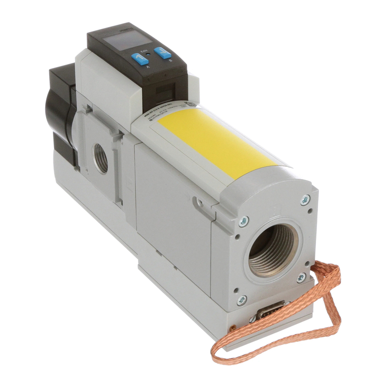
The VEAB-... proportional pressure regulator is intended to regulate a pressure
proportional to a specified setpoint value.
The valve is intended for use in an industrial environment.
1.2 Safety instructions
 The valve may only be used in its original status without unauthorized
modifications.
 Only use the valve if it is in perfect technical condition.
 Comply with all applicable national and international regulations.
 Comply with specified limits (èChapter 13, Technical data).
 Take into consideration the ambient conditions at the location of use.
1.3 Training of specialized personnel
Only qualified personnel may perform installation, commissioning, maintenance
and disassembly of the valve. The specialized personnel must be familiar with the
installation and operation of electrical and pneumatic control systems.
2 Design
2.1 In-line valve
2
4
5
1
3
6
1“Power” LED
2Electrical connection, plug M8
3Air port (2)
4Compressed air port (1)
5Exhaust air port (3)
6Through-holes for fastening the
valve
Fig. 1
For the vacuum type (VEAB-...-D14-...), compressed air port 1
(Pos. 4, Fig. 1) must be opened to the environment. The vacuum is
connected to port 3 (Pos. 5, Fig. 1) and the supply air is suctioned from
the environment through port 1 (Pos. 4, Fig. 1) (èSection 6.2).
2.2 Sub-base valve
1
2
33
1“Power” LED
2Electrical connection, plug M8
3Through-holes for fastening the
valve to the connection plate
Fig. 2
3 Product variants
Characteristic Type code Description
Basic function VEAB Piezo proportional pressure regulator
Valve type LIn-line valve
BSub-base valve
Valve function 26 2 x 2/2-way valve, normally closed
Pressure range D14 0 … –1bar
D12 0 … 0.2bar
D7 0 … 1bar
D2 0 … 2bar
D9 0 … 6bar
Pneumatic port F Flange/sub-base
Q4 Push-in connector 4 mm
Setpoint specification and
actual value output
V1 Voltage variant 0 … 10V
A4 Current variant 4 … 20 mA
Nominal operating
voltage
124V DC
Electrical connection R1 M8, 4-pin
Fig. 3
4 Function
A built-in pressure sensor records the pressure at the working port and compares
this value with the setpoint value. In the event of deviations between the setpoint
value and actual value, the valve regulates until the outlet pressure has reached
the setpoint value.
Fig. 4
5 Transport and storage
 Store the product in a dry, UV- and corrosion-protected environment. Ensure
storage times are short.
6 Installation
6.1 Mechanical
 Make sure there is sufficient space for the connecting line and tubing
connections. In this way you will prevent the connecting lines and the tubes from
being broken.
 Place the valve as close to the consumer as possible. This leads to improved
control precision and shorter response times.
Mounting options of the valve:
– Through-hold mounting of the in-line valve through 3 lateral through-holes
– Mounting of the in-line valve to the H-rail using H-rail mounting VAME-P7-T
– Mounting of the in-line valve to the mounting plate VAME-P7-Y
– Mounting of the sub-base valve using the sub-base VABM-....
The mechanical installation of the valve is described in the VAME-P7-T
(H-rail) and VAME-P...-Y (mounting plate) assembly instructions
(èwww.festo.com/sp).
6.2 Pneumatic (in-line valve)
Valves for standard operation (gauge pressure)
1. Connect the following pneumatic ports with tubing (èFig. 1):
– Compressed air port (1), Pos. 4
– Air port (2), Pos. 3
2. Mount a silencer Pos. 5at the exhaust port (3) or remove the exhaust air with
ducts.
Valve for vacuum operation (reversible operation, type VEAB-...-D14...)
1. Connect the following pneumatic ports with tubing (èFig. 1):
– Vacuum port (3), Pos. 5
– Air port (2), Pos. 3
2. At the compressed air port (1), Pos. 4, mount the silencer to protect the valve
against coarse dirt particles.
Operating medium
Note
Lubricated compressed air results in malfunctions and damage to the valve.
 Operate the valve only with unlubricated compressed air.
 Observe the requirements on compressed air quality (èChapter 13,
Technical data).
6.3 Electric
Warning
Electric voltage
Injury caused by electric shock, damage to machine and system
 For the electrical power supply, use only PELV circuits in accordance with
IEC60204-1/EN 60204-1.
 Use only voltage sources that ensure a reliable electric separation from the
mains network in accordance with IEC60204-1/EN60204-1.
 Observe the requirements of IEC 60204-1/EN 60204-1 for PELV circuits.
Note
Long signal lines reduce interference immunity.
 Signal lines must be shorter than 30 m.
 If a screened cable is used, earth the insulation at the cable end farther away
from the valve.
1. Install electrical connecting cable without squeezing, buckling or stretching.
2. Screw electrical connecting cable onto the M8 plug connector (èFig. 1).
– Tightening torque maximum 1.2 Nm.
Plug M8, 4-pin
Plug pattern Pin Allocation
1+ 24V DC
2+ Setpoint value
3GND
4+ Actual value
Fig. 5
7 Commissioning
Note
 Keep the valve away from high-frequency radiation (e.g., from radio sets,
mobile telephones or other interference-emitting devices). In this way,
increased tolerances of the outlet pressure are prevented.
The valve interprets setpoint signals under 0.5% of the upper setpoint value as
0 V and/or 4 mA. In this case, the outlet pressure is set to the ambient pressure.
1. Check operating conditions and limit values (èChapter 13, Technical data).
2. Switch on compressed air supply.
3. Check pneumatic connection points for tightness.
4. Connect the valve to a setpoint signal.
5. Switch on the operating voltage (Pin 1).
Note
 When decommissioning the valve, switch off the setpoint voltage first, then
the operating voltage and finally the compressed air supply.
8 Maintenance and care
Warning
Risk of injury
Accidental movements of the connected actuator technology and uncontrolled
movements of loose tubing can cause injury to people or material damage.
 Before all maintenance work, depressurize the valve and pneumatic
connecting lines.
1. Switch off the following energy sources to clean the outside:
– compressed air
– operating voltage
2. Clean the outside of the valve with a soft cloth. Do not use aggressive cleaning
agents.
9 Disassembly
Warning
Risk of injury
Accidental movements of the connected actuator technology and uncontrolled
movements of loose tubing can cause injury to people or material damage.
 Before disassembly, depressurize the valve and pneumatic connecting lines.
1. Depressurize the valve and pneumatic connecting lines.
2. Switch off the operating voltage.
3. Remove electrical connecting cable.
4. Remove compressed air lines.
5. Disassemble the valve (èAssembly instructions).
10 Accessories
èwww.festo.com/catalogue
11 Diagnostics
1
1“Power” LED
Fig. 6
“Power” LED
LED
display
Status and significance
LED illuminated green:
– The operating voltage is present and within the permissible range.
– The setpoint signal lies in the permissible range
(0 … 10.8V and/or 2.5 … 20.5mA).
– No error
LED flashing red:
– The operating voltage lies above the permissible range (>29V).
LED flashes alternately red and green:
– The setpoint signal lies above the permissible range (>10.8V and/or >20.5mA).
– The setpoint signal lies below the permissible range (<2.5mA).
LED is off:
The operating voltage does not lie at or below the permissible range (<19V).
Fig. 7
12 Fault clearance
Malfunction Possible cause Remedy
Valve does not react Operating voltage not applied
(èFig. 7)
Check the operating voltage
connection.
No setpoint voltage (èFig. 7) Check the controller and
connection.
Valve faulty Send the valve to the Festo repair
service.
Flow rate too low Restriction of the flow cross
section due to connection
technology (swivel fittings).
Use alternative connection
technology.
Pressure constant
despite modified
setpoint specification
Supply cable breakage; the last
outlet pressure set is maintained
but not regulated. Slow pressure
drop due to leakage.
Replace supply cable.
Setpoint value not
reached
Inlet pressure p1 not present Increase the inlet pressure p1.
Observe the permissible
maximum operating pressure
(èChapter 13).
Fig. 8
13 Technical data
Characteristic Specification/value
Design Propor tional pressure regulator
Assembly position Any
Operating medium Compressed air in accordance with
ISO 8573-1:2010 [7:4:4],
inert gases
Note on the operating medium Lubricated operation not possible
Inlet pressure 1 (vacuum, at port 3)
VEAB-...-D14-... [bar] –1
Inlet pressure 1 (at port 1)
VEAB-...-D12-... [bar] 0 … 1
VEAB-...-D7-... [bar] 0 … 3
VEAB-...-D2-... [bar] 0 … 4
VEAB-...-D9-... [bar] 0 … 6.5
Pressure control range
VEAB-...-D14-... [bar] –0.005 … –1
VEAB-...-D12-... [bar] 0.001 … 0.2
VEAB-...-D7-... [bar] 0.005 … 1
VEAB-...-D2-... [bar] 0.01 … 2
VEAB-...-D9-... [bar] 0.03 … 6
Accuracies
Repeat accuracy [%] ±0.4 FS (full scale)
Hysteresis [%] Max. 0.25 FS (full scale)
Hyteresis 0.2 bar variant (D12) [%] Max. 0.5 FS (full scale)
Linearity error [%] Max. 0.5 FS (full scale)
Linearity error 0.2 bar variant (D12) [%] Max. 0.8 FS (full scale)
Analogue output [%] 2 FS (full scale)
Degree of protection IP65 (completely mounted)
Permissible temperature range
Environment [°C] 0 … +50
Medium [°C] +5 … +50 (non-condensing)
Storage [°C] –20 … +70
Electromagnetic compatibility (EMC)1)
– Interference emission
– Interference immunity
See declaration of conformity
èwww.festo.com
1) The product is intended for use in industrial environments. Outside of industrial environments, e.g. in
commercial and mixed-residential areas, actions to suppress interference may have to be taken.
Feature Specification/value
Nominal operating voltage [V DC] 24
Operating voltage range [V DC] 19 … 29
Permissible residual ripple of operating
voltage
[%] 10
Maximum current consumption [A] 0.4
Setpoint value
Analogue input (current variant) [mA] 4 … 20
Analogue input (voltage variant) [V] 0 … 10
Input resistance setpoint value
At 4 … 20mA [Ω] 250
At 0 … 10VDC [kΩ] 10
Actual value
Analogue output (current variant) [mA] 4 … 20
Analogue output (voltage variant) [V] 0 … 10
Vibration and shock resistance (in accordance with IEC 60068)
Vibration (part 2 – 6)
Mounting with through-holes Severity level 2 (SG2)1)
Mounting to H-rail, mounting plate, terminal strip Severity level 1 (SG1)1)
Shock (part 2 – 27)
Mounting with through-holes Severity level 2 (SG2)1)
Mounting to H-rail, mounting plate, terminal strip Severity level 1 (SG1)1)
Continuous shock (part 2 – 27)
Mounting with through-holes Severity level 1 (SG1)1)
Mounting to H-rail, mounting plate, terminal strip Severity level 1 (SG1)1)
Materials
Housing PA, reinforced
Screws Steel, hardened and tempered;
steel,galvanized
Seals Nitrile rubber
Weight
Sub-base valve [g] Approx. 55
In-line valve [g] Approx. 55
1) Explanation of the severity level èFig. 10 … Fig. 12
Fig. 9
Vibration load
Frequency range [Hz] Acceleration [m/s2]Deflection [mm]
Severity
level 1
SL2 SL1 SL2 SL1 SL2
2 … 8 2 … 8 ––±3.5 ±3.5
8 … 27 8 … 27 10 10 – –
27 … 58 27 … 60 ––±0.15 ±0.35
58 … 160 60 … 160 20 50 – –
160 … 200 160 … 200 10 10 – –
Fig. 10
Shock load
Acceleration [m/s2]Duration [ms] Shocks per direction
SL1 SL2 SL1 SL2 SL1 SL2
±150 ±300 11 11 5 5
Fig. 11
Continuous shock load
Acceleration [m/s2]Duration [ms] Shocks per direction
±150 61000
Fig. 12
This manual suits for next models

5

Other Festo Control Unit manuals

Festo SPC200-COM-PDP User manual

Festo

Festo SPC200-COM-PDP User manual

Festo VTSA Series Operating and installation instructions

Festo

Festo VTSA Series Operating and installation instructions

Festo SLG-Z Series User manual

Festo

Festo SLG-Z Series User manual

Festo CP-FB8-E Parts list manual

Festo

Festo CP-FB8-E Parts list manual

Festo VMPA1-HS User manual

Festo

Festo VMPA1-HS User manual

Festo VOFC-LT-M32C Series User manual

Festo

Festo VOFC-LT-M32C Series User manual

Festo LF-D Series User manual

Festo

Festo LF-D Series User manual

Festo VOFA-L26-T52-M Series User manual

Festo

Festo VOFA-L26-T52-M Series User manual

Festo Smart cubic CPA-SC Series User manual

Festo

Festo Smart cubic CPA-SC Series User manual

Festo CPE Series User manual

Festo

Festo CPE Series User manual

Festo CDVI5.0 User manual

Festo

Festo CDVI5.0 User manual

Festo HSP-AE-IO Series Reference guide

Festo

Festo HSP-AE-IO Series Reference guide

Festo CP-FB13-E Parts list manual

Festo

Festo CP-FB13-E Parts list manual

Festo CP-E16 Series User manual

Festo

Festo CP-E16 Series User manual

Festo VZXF Series Parts list manual

Festo

Festo VZXF Series Parts list manual

Festo CPX-F8DE-P User manual

Festo

Festo CPX-F8DE-P User manual

Festo CPX-E-1CI User manual

Festo

Festo CPX-E-1CI User manual

Festo HEL Series Instruction Manual

Festo

Festo HEL Series Instruction Manual

Festo FRM S-B Series User manual

Festo

Festo FRM S-B Series User manual

Festo VZWM User manual

Festo

Festo VZWM User manual

Festo LFR-D Series User manual

Festo

Festo LFR-D Series User manual

Festo ZSB-1/8-B User manual

Festo

Festo ZSB-1/8-B User manual

Festo CPX-E-1CI User manual

Festo

Festo CPX-E-1CI User manual

Festo MPYE-5-***-B series User manual

Festo

Festo MPYE-5-***-B series User manual

Popular Control Unit manuals by other brands

Honeywell R7140G installation instructions

Honeywell

Honeywell R7140G installation instructions

Hayward SP0735 owner's manual

Hayward

Hayward SP0735 owner's manual

tau DC18 installation guide

tau

tau DC18 installation guide

Huawei ME309-562 Hardware guide

Huawei

Huawei ME309-562 Hardware guide

S&C TripSaver II Installation, Operation, and Configuration

S&C

S&C TripSaver II Installation, Operation, and Configuration

Nice Mindy A824 Instructions and warnings for the fitter

Nice

Nice Mindy A824 Instructions and warnings for the fitter

Racal Instruments 1260 VXI manual

Racal Instruments

Racal Instruments 1260 VXI manual

ETAS ES511.1 user guide

ETAS

ETAS ES511.1 user guide

Digi XBee SX 868 user guide

Digi

Digi XBee SX 868 user guide

Stafer 590.C.SM.00 user manual

Stafer

Stafer 590.C.SM.00 user manual

KSB LevelControl Basic 2 Installation & operating manual

KSB

KSB LevelControl Basic 2 Installation & operating manual

PRASTEL M1000E quick start guide

PRASTEL

PRASTEL M1000E quick start guide

Vega VEGADIS 176 Ex Safety instructions

Vega

Vega VEGADIS 176 Ex Safety instructions

Enerpac VP Series instruction sheet

Enerpac

Enerpac VP Series instruction sheet

Xaoc Devices Drezno II Operator's manual

Xaoc Devices

Xaoc Devices Drezno II Operator's manual

Pacific Recorders & Engineering Corporation LSM-10 Technical manual

Pacific Recorders & Engineering Corporation

Pacific Recorders & Engineering Corporation LSM-10 Technical manual

Resol VA300 manual

Resol

Resol VA300 manual

Behringer 2500 Series quick start guide

Behringer

Behringer 2500 Series quick start guide

manuals.online logo
manuals.online logoBrands
  • About & Mission
  • Contact us
  • Privacy Policy
  • Terms and Conditions

Copyright 2025 Manuals.Online. All Rights Reserved.