IEF Werner 115/42 User manual

June 2018 Translation of the original operating instructions
MAN_EN_1057398_Module115-42(B)_R3b.doc Module 115/42 (B) Page1 of 47
IEF-Werner GmbH
Wendelhofstraße 6
78120 Furtwangen - Germany
Phone: + 49 7723-925-0
Fax: + 49 7723-925-100
www.IEF-Werner.de
Translation of the original instructions
Module 115/42 (B)
Issue: June 2018
Article no.: 1057398

Translation of the original instructions June 2018
Page 2 of 47 Module 115/42 (B) MAN_EN_1057398_Module115-42(B)_R3b.doc
Change History:
Trademarks and trade names are used without any warranty of their free usability. Texts and
examples were created with great care. Nevertheless, errors cannot be excluded. IEF-Werner GmbH
does not assume legal responsibility nor any liability for missing or incorrect statements and their
consequences.
IEF-Werner GmbH reserves the right to modify or improve the software or hardware or parts of it, as
well as the supplied documentation or parts of it, without previous notice.
IEF-Werner GmbH expressly reserves all rights for replication and photomechanical reproduction,
including in extracts.
We are always grateful for suggestions for improvements and information about errors.
© June 2018, IEF-Werner GmbH
Document Code
Date
Revision
MAN_EN_1057398_Modul115-42_R1a.doc
26.01.2007
New release of the English document according to the
original German instruction:
MAN_DE_1057397_Modul115_42_R1b.doc
MAN_EN_1057398_Modul115-42_R1b.doc
19.04.2010
New article no. of clamping elements and drive units
MAN_EN_1057398_Modul115-42_R2a.doc
14.12.2013
Translation of the current original German instruction:
MAN_DE_1057397_Modul115_42_R3b.doc
MAN_EN_1057398_Modul115-42_R2b.doc
21.01.2015
Content structure restructured in chapter 3
MAN_EN_1057398_Modul115-42(B)_R3a.doc
08.01.2018
Revision due to use of other slides / guides
MAN_EN_1057398_Modul115-42(B)_R3b.doc
04.06.2018
Modification in chapter 4 maintenance
(Module 115/42 or Module 115/42 B).

June 2018 Translation of the original instructions
MAN_EN_1057398_Module115-42(B)_R3b.doc Module 115/42 (B) Page 3 of 47
Table of Contents
1Safety 5
1.1 Definition or warning notes 5
1.2 General warning notes 5
1.3 Special hazard warnings 6
2Intended use 7
2.1 Reasonably foreseeable misuse 7
3Assembly instructions 8
3.1 Installation position 8
3.2 Overview of motor installation variants 8
3.2.1 Module 115/42 or 115/42 B, installation variant 1 9
3.2.2 Module 115/42 or 115/42 B, installation variant 5 10
3.3 Attachment 11
3.3.1 Installation of actuators 13
3.4 Wiring 14
3.4.1 Motors 14
3.4.2 Initiators 14
3.4.2.1 Technical data of initiators 15
3.4.2.2 Plug for end position switch 16
3.4.3 Cable routing 16
3.5 Technical data 17
3.5.1 Tightening torques for screw connections (general) 17
3.5.2 Technical data of the linear module 115/42 or 115/42 B 17
3.5.3 Type label 18
3.5.4 Technical data when using a planetary gear 18
3.5.5 Axis distances and tooth numbers 19
3.5.6 Load cases 20
3.5.6.1 Torques and carrying capacities 20
3.5.6.2 Tilting of the carriage unit at lateral load 21
4Maintenance 22
5Troubleshooting 23
6Repair instructions 25
6.1 Factory-setting of the toothed belt tension 26
6.2 Replace toothed belt 27
6.3 Reference side of the guide system 29
7Parts lists and drawings 30
7.1 Module 115/42 30

Translation of the original instructions June 2018
Page 4 of 47 Module 115/42 (B) MAN_EN_1057398_Module115-42(B)_R3b.doc
7.2 Module 115/42 B 32
7.3 Slide Module 115/42 (L=195) 34
7.4 Slide Module 115/42 (L=300) 36
7.5 Slide Module 115/42 B (L=195) 38
7.6 Slide Module 115/42 B (L=300) 40
7.7 (Belt) Gearbox module 80/15 42
7.8 Flange 44
7.9 Design-specific assemblies/components 45
7.9.1 Installation flange gearbox (e.g. planetary gear type PLFE64) 45
7.9.2 Overview clamping elements 46
8Declaration of incorporation 47

June 2018 Translation of the original instructions Safety
MAN_EN_1057398_Module115-42(B)_R3b.doc Module 115/42 (B) Page 5 of 47
1 Safety
1.1 Definition or warning notes
WARNING
Indicates potential danger. Non-observance of the safety provisions may
cause death or severe injury.
CAUTION
Indicates potential danger. Non-observance of the safety provisions may
cause property damage or injury.
NOTE
Offers additional information.
1.2 General warning notes
The module must only be commissioned by specialists who received safety-technical
instruction and are able to assess potential dangers. Furthermore, all chapters of these
operating instructions must have been read and understood completely.
WARNING
The system must be powered down for all assembly, disassembly or
repair work. There is a high danger of injury.
WARNING OF HOT SURFACE
During operation, heating of the motor, in particular of stepper motors, can
cause the burns of the skin when touching the motor. Install a protective
device, if possible! Do not touch the marked areas or wait for an adequate
cooling time.
CAUTION
Motor connectors must not be inserted or disconnected when live. Risk of
burning of the contacts and risk of flying sparks.

Safety Translation of the original instructions June 2018
Page 6 of 47 Module 115/42 (B) MAN_EN_1057398_Module115-42(B)_R3b.doc
CAUTION
Linear modules always have to be operated in connection with suitable safety
devices (e.g., safety cell, protective room, protective housing,
light curtain).
NOTE
Observe the Declaration of Incorporation (see section Declaration of
incorporation, page 47).
1.3 Special hazard warnings
In addition, this Original User's Manual also contains the following special hazard warning:
DANGER FROM CRUSHING
These places of the components pose the danger of crushing limbs in
operation.

June 2018 Translation of the original instructions Intended use
MAN_EN_1057398_Module115-42(B)_R3b.doc Module 115/42 (B) Page 7 of 47
2 Intended use
The linear unit module 115/42 (see Figure 1) or module 115/42 B was designed for use in the
commercial area. Use of a high-quality guide warrants high dynamics and good running
behaviour. The internal guide system is protected from contamination by the toothed belt.
Additionally, the guide elements have special seals that protect the guide tracks from coarse
dirt.
Figure 1: Module 115/42
The linear unit module 115/42 or module 115/42 B can be used for many applications. They
usage areas range from stop adjustment in the wood industry to equipment systems for
SMD-components, joining and pressing processes in precision mechanics, loading and
unloading stations of tool machines, to manipulators for the packaging industry.
2.1 Reasonably foreseeable misuse
The linear module 115/42 or 115/42 B is not to be used for certain applications such as the
transport of persons and animals or as a pressing/bending device for cold working of metal.
Use of the linear module without additional measures is also not possible in special fields of
application, such as the chemical or food industry or in explosive atmospheres.
In case of doubt, consult the manufacturer.

Assembly instructions Translation of the original instructions June 2018
Page 8 of 47 Module 115/42 (B) MAN_EN_1057398_Module115-42(B)_R3b.doc
3 Assembly instructions
3.1 Installation position
The installation position is optional, i.e. the linear module can be used horizontally as well as
vertically.
CAUTION
In the vertical installation position, use only motors with spring-operated brake
to prevent the lowering of the drive in de-energized condition!
3.2 Overview of motor installation variants
Figure 2: Installation variants module 115/42 or 115/42 B

June 2018 Translation of the original operating instructions Assembly instructions
MAN_EN_1057398_Module115-42(B)_R3b.doc Module 115/42 (B) Page 9 of 47
3.2.1 Module 115/42 or 115/42 B, installation variant 1
Figure 3: Module 115/42 or 115/42 B, subassembly number 1000901, installation variant 1

Assembly instructions Translation of the original operating instructions June 2018
Page 10 of 47 Module 115/42 (B) MAN_EN_1057398_Module115-42(B)_R3b.doc
3.2.2 Module 115/42 or 115/42 B, installation variant 5
Figure 4: Module 115/42 or 115/42 B, subassembly number 1000901, installation variant 5

June 2018 Translation of the original instructions Assembly instructions
MAN_EN_1057398_Module115-42(B)_R3b.doc Module 115/42 (B) Page 11 of 47
3.3 Attachment
In most use cases, the linear module 115/42 or 115/42 B is attached to a level mounting
surfaced with clamping profiles/clamping elements (see Figure 5, bottom). The carriage moves
freely.
The linear module should not be attached otherwise, e.g. by additional bores in the basic unit.
These bores will nearly always lead to clamping of the guide basis and damage to internal
parts of the module.
CAUTION
The clamping surface should have a levelness of 0.1 mm/m².
Figure 5: Attachment with clamping profiles / clamping elements
NOTE
For an overview of the different clamping elements, see the section Overview
clamping elements, page 46.
Clamping
element
Clamping
element

Assembly instructions Translation of the original instructions June 2018
Page 12 of 47 Module 115/42 (B) MAN_EN_1057398_Module115-42(B)_R3b.doc
DANGER FROM CRUSHING
These places of the components pose the danger of crushing limbs.
There is danger of crushing at the start and end of a stroke (see Figure 6, below).
Figure 6: Possible crushing points

June 2018 Translation of the original instructions Assembly instructions
MAN_EN_1057398_Module115-42(B)_R3b.doc Module 115/42 (B) Page 13 of 47
Figure 7 shows the drilling pattern of a standard carriage.
Figure 7: Drilling pattern standard carriage
Figure 8 shows a centering ring to take up clamping elements:
Figure 8: Centring ring (article no.: 1024021)
The threaded bores M6 make different axis configurations possible on the carriage, possibly
using an adapter plate.
The recesses Ø12 serve to centre clamping elements with supply option.
3.3.1 Installation of actuators
Actuators to be installed on the linear module (pick-up modules, cylinders) are usually
attached to the linear unit using the drill template on the carriage (see Figure 7, above).
Assembly instructions Translation of the original instructions June 2018
Page 14 of 47 Module 115/42 (B) MAN_EN_1057398_Module115-42(B)_R3b.doc
3.4 Wiring
3.4.1 Motors
CAUTION
The electrical connection of the motors is performed according to the motor
data sheet. For customer-specific motors, the data sheet must be requested
from the respective manufacturer and the motor connected accordingly.
3.4.2 Initiators
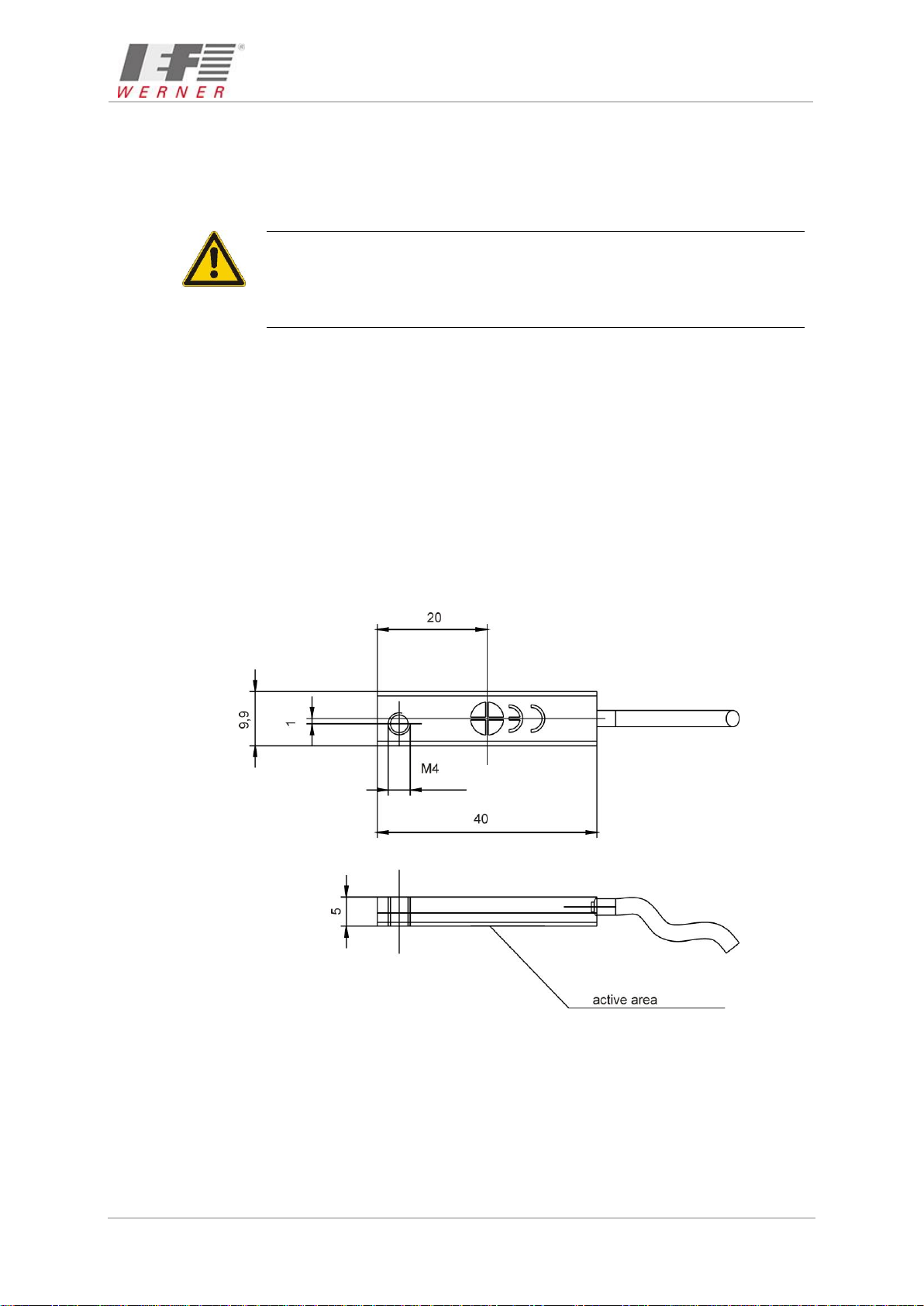
Inductive proximity switches (PNP normally closed contact, article no.: 025165) are used as
standard limit switches for the running path (see Figure 9 and Figure 10). These switches are
no safety limit switches pursuant to EN60204-1. Optionally, (also subsequently) an additional
reference point switch (PNP normally open contact article no.: 726744), can be installed in the
linear module 115/42 or 115/42 B. The active button is marked with a coloured circle. Normally
closed contacts are marked with a green, normally open contacts with a red dot. The initiators
and their supply lines are protected in a cable channel integrated in the basic unit, and are
wired to a joint plug.
A plastic strip serves to cover the cable channel. An initiator can be replaced or relocated
easily after removal of this plastic strip from the cable channel.
Figure 9: Scaled sketch of inductive proximity switch

June 2018 Translation of the original instructions Assembly instructions
MAN_EN_1057398_Module115-42(B)_R3b.doc Module 115/42 (B) Page 15 of 47
Figure 10: Connection allocation PNP normally closed contact
Figure 11: Connection allocation PNP normally open contact
3.4.2.1 Technical data of initiators
Parameter
Value
Operating voltage incl. residual ripple
(10 ... 30) VDC 15 %
Current load capacity
Ia200 mA
Voltage drop at Iamax.
2.5 V
Switching frequency
1,000 Hz
Own current consumption
15 mA
Nominal switching distance on steel
1.5 mm 10 %
Switching hysteresis
(3 ... 20) %
Reproducibility (U = const.)
0.01 mm
Operating temperature
- 25 C ... + 70 C
Protection class
IP 65
Short-circuit proof
yes
Protected against polarity reversal
yes
Figure 12: Technical data of initiators

Assembly instructions Translation of the original instructions June 2018
Page 16 of 47 Module 115/42 (B) MAN_EN_1057398_Module115-42(B)_R3b.doc
3.4.2.2 Plug for end position switch
The end position switch is assigned as follows (see Figure 13):
Pin-No.
Assignment
IEF-Werner cables
1
+ 24 V
brown
2
Limit switch negative direction
green
3
0 V
white
4
Limit switch positive direction
yellow
5
Reference switch
grey
Figure 13: Connection assignment plug end position switch
3.4.3 Cable routing
For all moving cables, suitable cable routing has to be used to effectively prevent cable
breaks.
The minimum radius rmin for cable routing chains is calculated for IEF-Werner cables according
to the following formula:
rmin 10 x cable diameter
When different cables are used, EN 60204 must be observed. In addition, it must be ensured
that a space reserve of 30% is kept free within the routing chains. A strain relief for the cables
has to be attached at the outlet of the cable routing chain.

June 2018 Translation of the original instructions Assembly instructions
MAN_EN_1057398_Module115-42(B)_R3b.doc Module 115/42 (B) Page 17 of 47
3.5 Technical data
3.5.1 Tightening torques for screw connections (general)
Screw 8.8
Tightening torque [Nm]
M3
1.1
M4
2.5
M5
5.0
M6
8.5
M8
21.0
M10
41.0
M12
71.0
Screw 12.9
Tightening torque [Nm]
M4 (guide rail
attachment)
4.9
3.5.2 Technical data of the linear module 115/42 or 115/42 B
Parameter
Value
Repeating accuracy
+/- 0.05 mm
Weight (without motor at stroke 0 mm)
8.85 kg
Weight increase per 100 mm stroke
0.95 kg
Maximum movement speed
5 m/s
Maximum acceleration
40 m/s²
Max. transferable feed force at
max. movement speed (5 m/s)
1,278 N
Max. torque Mx
150 Nm
Max. torque My
80 Nm
Max. torque Mz
150 Nm
Carrying capacity C1
2,000 N
Carrying capacity C2
800 N
Guide stiffness x
See Tilting of the carriage unit at lateral load,
page 21.
Area inertias of the profile cross-section at the centre of gravity:
Ix
677,502 mm4
Iy
1,868,985 mm4
Figure 14: Technical data

Assembly instructions Translation of the original instructions June 2018
Page 18 of 47 Module 115/42 (B) MAN_EN_1057398_Module115-42(B)_R3b.doc
3.5.3 Type label
Figure 15: Type label (example)
3.5.4 Technical data when using a planetary gear
Before commissioning, observe the possible input speeds of the gear manufacturers.
Too-high input speeds can lead to increased wear at the gear and/or thermal problems.
The accuracy of the linear unit is influenced by the reverse play of the gears.
Example:
The gear reverse play (S) is 9 angle minutes.
How high is the reverse play at the carriage of the linear unit?
Feed constant of the linear unit (Vk): 140 mm
Reverse play at the carriage =(Vk • S) / (360 x 60)
= (140 mm • 9) / (360 x 60)
= 0.058 mm
Consider the information of the respective gear manufacturer in any case.
e.g. www.neugart.de/index.php/gb/Produkte/Standardgetriebe
www.wittenstein-alpha.de/en/drive-systems.html

June 2018 Translation of the original instructions Assembly instructions
MAN_EN_1057398_Module115-42(B)_R3b.doc Module 115/42 (B) Page 19 of 47
3.5.5 Axis distances and tooth numbers
Figure 16: Explanations on the table axis distances, subassembly no.: 1000475
Comply with the following axis distances in the required standard reductions:
i
Z1 output
Z2 drive
Bore
diameter
of Z1
Length
of toothed
belt
AA
[mm]
Feed constant
[mm]
1:1
42
42
max.
Ø 32 mm
450 mm
120
140
2.1:1
42
20
max.
Ø 16 mm
390 mm
116.18
66.667
2.625:1
42
16
max.
Ø 14 mm
390 mm
120.73
53.333
3:1
42
14
max.
Ø 12 mm
375 mm
115.35
46.667

Assembly instructions Translation of the original instructions June 2018
Page 20 of 47 Module 115/42 (B) MAN_EN_1057398_Module115-42(B)_R3b.doc
3.5.6 Load cases
3.5.6.1 Torques and carrying capacities
Figure 17: Torques and carrying capacities
Excerpt from the technical data (Figure 14, page 17):
Parameter
Value
Max. torque Mx
150 Nm
Max. torque My
80 Nm
Max. torque Mz
150 Nm
Carrying capacity C1
2,000 N
Carrying capacity C2
800 N
Figure 18: Table torques and carrying capacities
This manual suits for next models
1
Table of contents
Other IEF Werner Control Unit manuals


