Viconics VT8600 Series User manual

1
Version 11
VT8600 Series User Interface Guide
Rooftop Unit, Heatpump and Indoor Air Quality Controller

2
Viconics Technologies Inc. www.viconics.com | [email protected]| Tel: (514) 321-5660 | Fax: (514) 321-4150
028-0427-11 October 2018
Table of Contents
Section 1
Introduction 4
User and Integrator Screens 4
Disclaimer 5
HMI Display 7
Section 2
User HMI for Hospitality 11
User HMI for Commercial 12
System Mode 13
Fan Mode Settings 13
Heating Only Configuration 14
Setpoint Adjustment Cooling 14
Setpoint Adjustment Heating 15
Other Functions 15
Customizable Color Options 16
Network Settings 18
ZigBee Network Settings 22
BACnet Network Settings 22
Modbus Network Settings 24
Configuration Screens 26
Setpoint Screens 49
Display Screens 54
Service View Screens 59
Test Outputs Screens 70
Language Selection Screens 73
Schedule Screens 75
ADR Screens 80
Wireless Screens 83
Lua Screens 94
Section 3
Appendix 97

SECTION 1
Introduction

4
Viconics Technologies Inc. www.viconics.com | [email protected]| Tel: (514) 321-5660 | Fax: (514) 321-4150
028-0427-11 October 2018
Introduction
This guide shows the User Interface instructions for the VT8300 Series Room Controller (Firmware Release version 1.7) for User and
Integrators.
User and Integrator Screens
The VT8300 Room Controller has dynamic screens and parameters that only appear on certain models or based on the presence of
a communication module (VCM). The LUA tab on the second menu screen, will also only show if a LUA script is uploaded to the Room
Controller.
See below legend screen details.
Read Only parameter
6/7 Configuration
Language English
Units °C
Low backlight 60 %
Night backlight 5 %
RH display Disable
Parameter Screen
Parameter XXXX
XXXXParameter
XXXXParameter XXXXParameter
Adjustable parameter
Some parameters appear only when Zig-
Bee wireless communication module is
installed, or if a LUA script is uploaded.
Change Value
Previous
screen
Next
screen Return to pre-
vious menu
Notes
1. When any change is made to a parameter, the value is permanently saved in the database when the
next parameter is selected or another screen is opened. This event is true only if a parameter was
changed locally on the Room Controller. Making changes through BACnet will not have the same
outcome. If permanent changes need to be done remotely through BACnet, use priority 1, 2 or 3, or
write to relinquish default (priority 17)
2. The ZigBee Pro communication module must be Revision 10 (R10) or later to support newly
introduced devices such as water leak sensor and the ZigBee Green Power environmental sensor.
3. The Room Controller must be running Firmware version 1.7 or later to enable the Automatic Demand
Response (ADR) feature.

5
Viconics Technologies Inc. www.viconics.com | [email protected]| Tel: (514) 321-5660 | Fax: (514) 321-4150
028-0427-11 October 2018
Disclaimer
*Disclaimer
Standby screen: The Room Controller incorporates TFT-type LCD technology, and therefore,
necessary precautions are required to prevent the phenomenon of image retention (residual
image) from occurring.
Image retention may occur when a static image is displayed on the screen for a prolonged pe-
riod of time. This can cause a faint outline of the image to remain visible on the screen when the
screen is changed via the user menu, or a different image is uploaded and selected to be dis-
played. To minimize and prevent image retention, it is recommended to select the Screen Save
setting on the Standby screen selection from the setup menu Display 1/2. This setting switches
the display during periods of inactivity from the Home Screen.
It is recommended to use a black or medium gray image, or one with light color contrasts as the
screen saver to prevent this phenomenon from occurring. If the display still exhibits this phe-
nomenon, loading an all-black or all-medium gray image as the screen saver and displaying it for
upwards of 5 hours continuously minimizes this effect.
NOTE: Avoid placing the Room Controller in poorly ventilated areas, or in areas that may
create excess heat around the display.

HMI Display and Set-up
7
Viconics Technologies Inc. www.viconics.com | [email protected]| Tel: (514) 321-5660 | Fax: (514) 321-4150
028-0427-11 October 2018
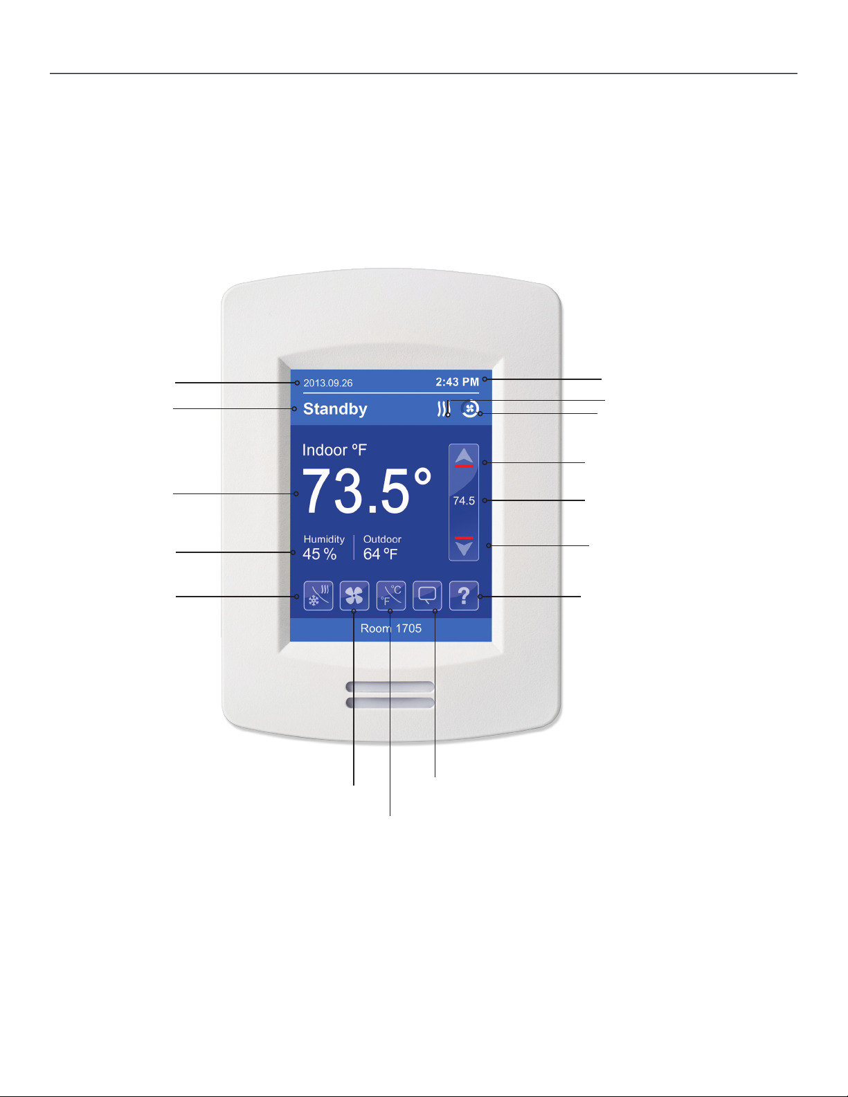
HMI Display
The below shows a typical user interface for the hospitality industry. The User HMI is configurable and allows display functions such
as Date, Time, Humidity, Outdoor Temperature, and Setpoint to be enabled or disabled by setting various parameters.
Time
System Status
Fan Status
Increase Temperature Setpoint
Actual Setpoint
Decrease Temperature Setpoint
Indoor Humidity &
Outdoor Temperature
Indoor Temperature
Occupancy
Status
Help
Language Selection
Temperature Units
Fan Mode
System Mode
Date

8
Viconics Technologies Inc. www.viconics.com | [email protected]| Tel: (514) 321-5660 | Fax: (514) 321-4150
028-0427-11 October 2018
Touch and hold this point
for 3 seconds to enter setup mode
Note: If a conguration/installer
password is activated to prevent
unauthorised access to the
conguration menu parameters, a
password entry prompt shows to
prevent access to device
conguration components.
Enter Set-up Screen
SET UP 1/2
Return to
previous menu
1/2 Setup
Network
Configuration
Setpoints
Display
Service view
Test Outputs
Discover Mode shows wireless
ZigBee network. Icon not shown if
ZigBee communication module not
installed
BACnet MS/TP, Modbus and ZigBee network settings (ZigBee
network settings appear only if a communication module is installed)
Parameter configuration menu
Setpoint settings
Status display (Read Only)
Display settings
Test outputs settings
9
Viconics Technologies Inc. www.viconics.com | [email protected]| Tel: (514) 321-5660 | Fax: (514) 321-4150
028-0427-11 October 2018
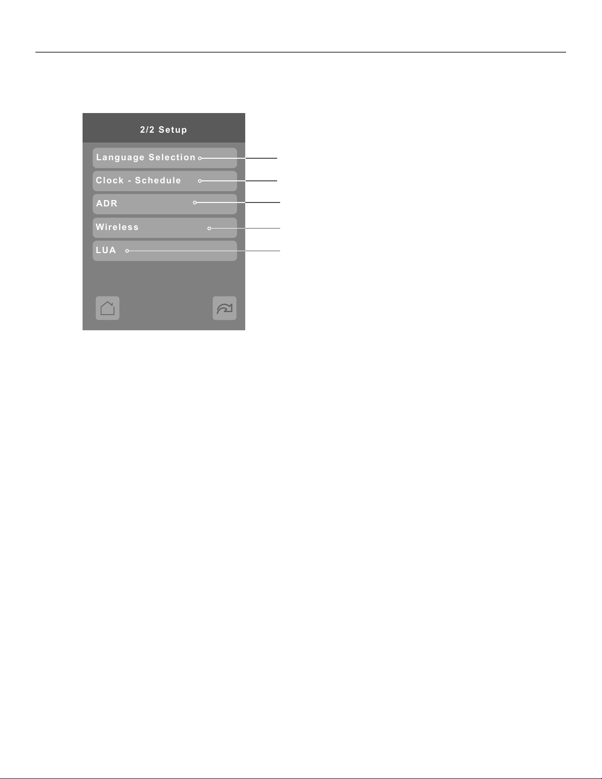
SET UP 2/2
2/2 Setup
Clock - Schedule
LUA
Wireless
Language Selection
ADR
Automatic Demand Response
LUA scripting (shows only if LUA script uploaded)
Wireless Ecosystem settings (shows only if ZigBee
communication module installed)
Select language
Set clock, schedule and occupancy

SECTION 2
Customized Screens
Other manuals for VT8600 Series
2
This manual suits for next models
1
Table of contents
Other Viconics Control Unit manuals


