Hewlett Packard Enterprise Synergy 660 Gen10 User manual

HPE Synergy 660 Gen10 Compute Module
User Guide
Part Number: 876828-005
Published: April 2019
Edition: 5
Abstract
This document is for the person who installs, administers, and troubleshoots server blades.
Hewlett Packard Enterprise assumes you are qualified in the servicing of computer equipment and
trained in recognizing hazards in products with hazardous energy levels.

© Copyright 2017, 2019 Hewlett Packard Enterprise Development LP
Notices
The information contained herein is subject to change without notice. The only warranties for Hewlett Packard
Enterprise products and services are set forth in the express warranty statements accompanying such
products and services. Nothing herein should be construed as constituting an additional warranty. Hewlett
Packard Enterprise shall not be liable for technical or editorial errors or omissions contained herein.
Confidential computer software. Valid license from Hewlett Packard Enterprise required for possession, use,
or copying. Consistent with FAR 12.211 and 12.212, Commercial Computer Software, Computer Software
Documentation, and Technical Data for Commercial Items are licensed to the U.S. Government under
vendor's standard commercial license.
Links to third-party websites take you outside the Hewlett Packard Enterprise website. Hewlett Packard
Enterprise has no control over and is not responsible for information outside the Hewlett Packard Enterprise
website.
Acknowledgments
Intel®, Itanium®, Pentium®, Xeon®, Intel Inside®, and the Intel Inside logo are trademarks of Intel Corporation
in the U.S. and other countries.
Microsoft® and Windows® are either registered trademarks or trademarks of Microsoft Corporation in the
United States and/or other countries.
Adobe® and Acrobat® are trademarks of Adobe Systems Incorporated.
Java® and Oracle® are registered trademarks of Oracle and/or its affiliates.
UNIX® is a registered trademark of The Open Group.

Component identification
Front panel LEDs and buttons
Item Description Status
1 UID LED Solid blue = Activated
Flashing blue (1 Hz/cycle per sec)
= Remote management or
firmware upgrade in progress
Off = Deactivated
2 Health status LED Solid green = Normal
Flashing green (1 Hz/cycle per
sec) = iLO is rebooting
Flashing amber = System
degraded
Flashing red (1 Hz/cycle per sec) =
System critical
Table Continued
Component identification 3

Item Description Status
3 Mezzanine NIC status LED Solid green= Link on any
Mezzanine NIC
Flashing green= Activity on any
Mezzanine NIC
Off = No link or activity on any
Mezzanine NIC
4 Power On/Standby button and
system power LED Solid green = System on
Flashing green (1 Hz/cycle per
sec) = Performing power on
sequence
Solid amber = System in standby
Off = No power present1
1 If all other LEDs are off, then no power is present to the compute module. (For example, facility power is not present,
power cord is not attached, no power supplies are installed, power supply failure has occurred, or the compute module is
not properly seated.) If the health LED is flashing green while the system power LED is off, the Power On/Standby button
service is initializing or that an iLO reboot is in progress.
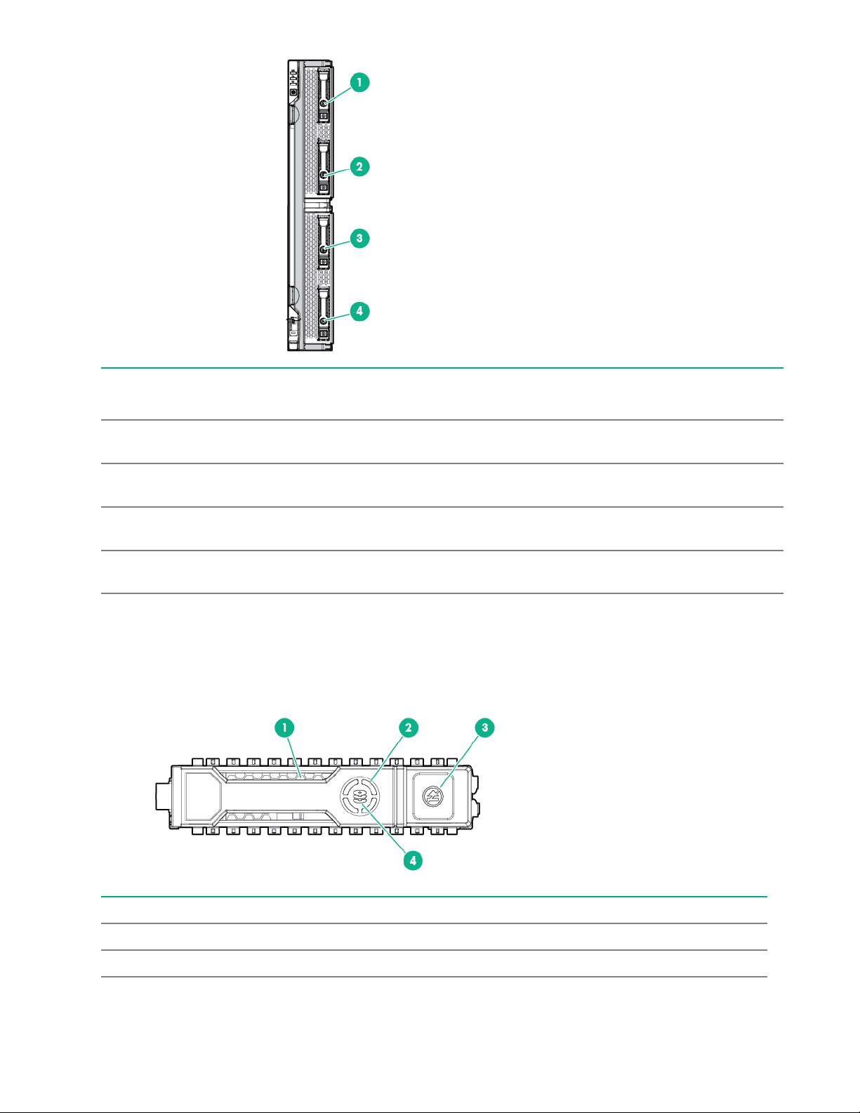
Front panel components
1
2
3
4
7
8
7
5
6
6
5
Item Description
1 Drive Box 1, Drive bay 11
2 Drive Box 1, Drive bay 21
3 Drive Box 2, Drive bay 11
4 Drive Box 2, Drive bay 21
5 iLO Service Port (169.254.1.2) (located behind the Serial label pull tab)
Table Continued
4Component identification

Item Description
6 External USB (located behind the Serial label pull tab)
7 Compute module handle release latch
8 Compute module handle
1 If uFF drives (the SFF Flash Storage Adapter) are installed in the drive bays, the drive bay numbering is different. For
more information, see Drive numbering.
Serial label pull tab information
The serial label pull tab is located on the front panel of the compute module. To locate the serial label pull tab,
see Front panel components. The serial label pull tab provides the following information:
• Product serial number
• HPE iLO information
• QR code that points to mobile-friendly documentation
Drive numbering
Depending on the configuration, the drive bay numbering on this compute module will vary. Supported
configurations on this compute module are shown in the following table.
Compute module model Configuration Drive support
SAS model Standard backplane with
embedded controller or supported
controller option
Four SFF hot-plug SAS drive bays
with support for up to 4 SFF HDDs
or SSDs
SATA model Chipset SATA with embedded
controller or supported controller
option
Four SFF hot-plug SATA drive
bays with support for the following:
• Up to 4 SFF SATA HDDs or
SSDs
• Up to 8 uFF SATA HDDs (with
the SFF flash adapter for each
2 uFF drives)
Component identification 5
Item SAS configuration SATA configuration* Expansion storage
configuration
1 1 Drive box 1, drive bay 1 and
101
Drive box 1, drive bay 1
2 2 Drive box 1, drive bay 2 and
102
Drive box 1, drive bay 2
3 1 Drive box 2, drive bay 1 and
101
Drive box 2, drive bay 1
4 2 Drive box 2, drive bay 2 and
102
Drive box 2, drive bay 2
The driveless model is not shown, as it does not have drive bays and does support for any drives.
*SATA drives are supported only with the HPE Synergy 480 Gen9 Compute Module backplane.
Hot-plug drive LED definitions
Item LED Status Definition
1 Locate Solid blue The drive is being identified by a host application.
Flashing blue The drive carrier firmware is being updated or requires an update.
Table Continued
6Component identification
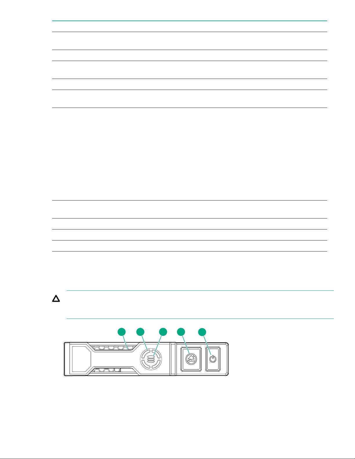
Item LED Status Definition
2 Activity
ring
Rotating green Drive activity
Off No drive activity
3 Do not
remove
Solid white Do not remove the drive. Removing the drive causes one or more of
the logical drives to fail.
Off Removing the drive does not cause a logical drive to fail.
4 Drive
status
Solid green The drive is a member of one or more logical drives.
Flashing green The drive is doing one of the following:
• Rebuilding
• Performing a RAID migration
• Performing a strip size migration
• Performing a capacity expansion
• Performing a logical drive extension
• Erasing
• Spare part activation
Flashing amber/
green
The drive is a member of one or more logical drives and predicts the
drive will fail.
Flashing amber The drive is not configured and predicts the drive will fail.
Solid amber The drive has failed.
Off The drive is not configured by a RAID controller or a spare drive.
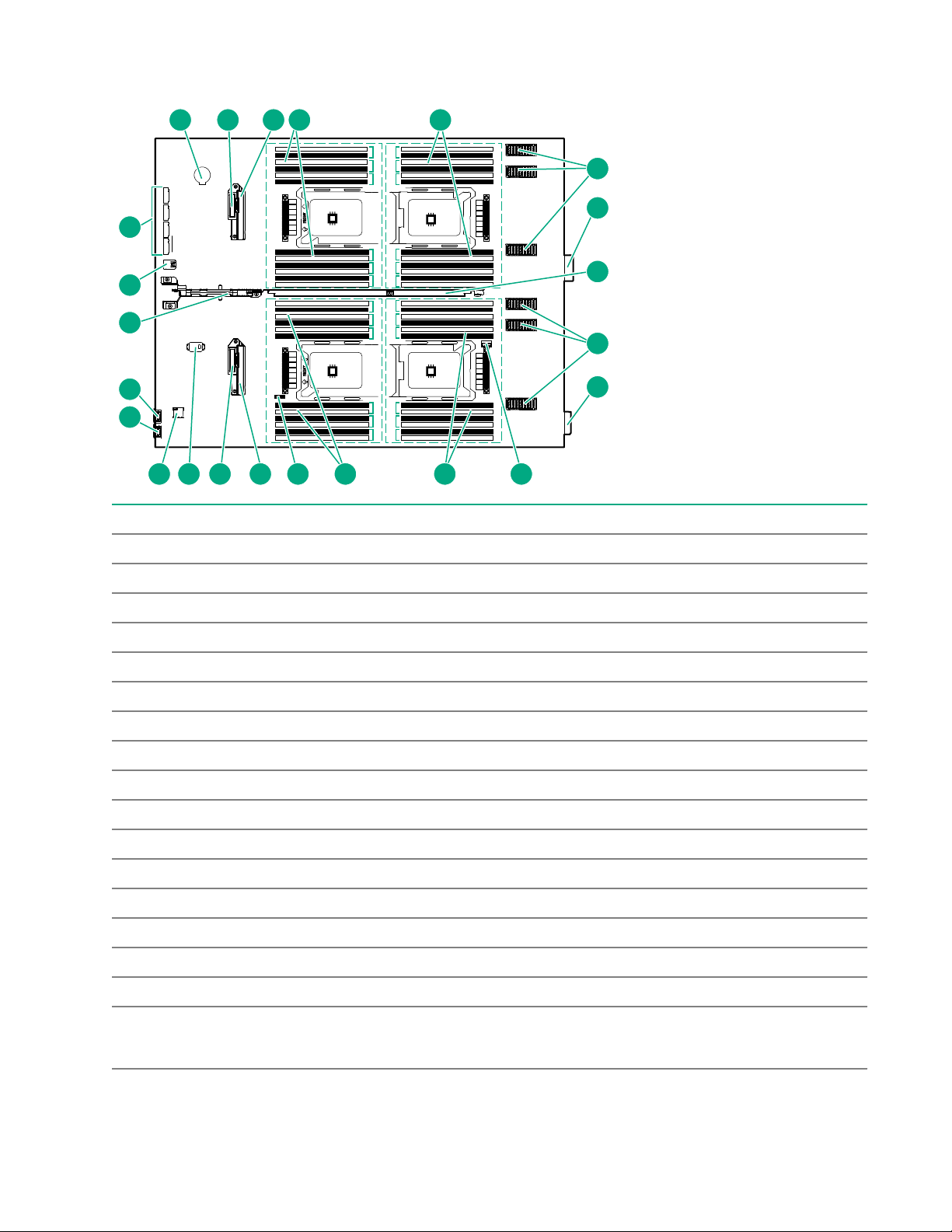
NVMe SSD LED definitions
The NVMe SSD is a PCIe bus device. A device attached to a PCIe bus cannot be removed without allowing
the device and bus to complete and cease the signal/traffic flow.
CAUTION: Do not remove an NVMe SSD from the drive bay while the Do not remove LED is flashing.
The Do not remove LED flashes to indicate that the device is still in use. Removing the NVMe SSD
before the device has completed and ceased signal/traffic flow can cause loss of data.
2 3 4 5
1
Component identification 7

Item LED Status Definition
1 Locate Solid blue The drive is being identified by a host application.
Flashing blue The drive carrier firmware is being updated or requires an update.
2 Activity
ring
Rotating green Drive activity
Off No drive activity
3 Drive
status
Solid green The drive is a member of one or more logical drives.
Flashing green The drive is doing one of the following:
• Rebuilding
• Performing a RAID migration
• Performing a stripe size migration
• Performing a capacity expansion
• Performing a logical drive extension
• Erasing
Flashing amber/
green
The drive is a member of one or more logical drives and predicts the
drive will fail.
Flashing amber The drive is not configured and predicts the drive will fail.
Solid amber The drive has failed.
Off The drive is not configured by a RAID controller.
4 Do not
remove
Solid white Do not remove the drive. The drive must be ejected from the PCIe bus
prior to removal.
Flashing white The drive ejection request is pending.
Off The drive has been ejected.
5 Power Solid green Do not remove the drive. The drive must be ejected from the PCIe bus
prior to removal.
Flashing green The drive ejection request is pending.
Off The drive has been ejected.
8Component identification

SFF flash adapter components and LED definitions
Item Component Description
1 Locate • Off—Normal
• Solid blue—The drive is being identified by a host application.
• Flashing blue—The drive firmware is being updated or requires
an update.
2 uFF drive ejection latch Removes the uFF drive when released.
3 Do not remove LED • Off—OK to remove the drive. Removing the drive does not
cause a logical drive to fail.
• Solid white—Do not remove the drive. Removing the drive
causes one or more of the logical drives to fail.
4 Drive status LED • Off—The drive is not configured by a RAID controller or a spare
drive.
• Solid green—The drive is a member of one or more logical
drives.
• Flashing green (4 Hz)—The drive is operating normally and has
activity.
• Flashing green (1 Hz)—The drive is rebuilding, erasing, or
performing a RAID migration, stripe size migration, capacity
expansion, logical drive extension, or spare activation.
• Flashing amber/green (1 Hz)—The drive is a member of one or
more logical drives that predicts the drive will fail.
• Solid amber—The drive has failed.
• Flashing amber (1 Hz)—The drive is not configured and predicts
the drive will fail.
5 Adapter ejection release latch
and handle
Removes the SFF flash adapter when released.
Component identification 9
System board components
M1
M2
M3
M4
M5
M6
1
2
3
4
5
6
1
2
3
4
5
6
7
8
9
10
11
12
7
8
9
10
11
12
1
2
3
4
5
6
1
2
3
4
5
6
7
8
9
10
11
12
7
8
9
10
11
12
Ch 6 Ch 5 Ch 4
Ch 1 Ch 2 Ch 3Ch 6 Ch 5 Ch 4
Ch 1 Ch 2 Ch 3 Ch 6 Ch 5 Ch 4
Ch 1 Ch 2 Ch 3Ch 6 Ch 5 Ch 4
Ch 1 Ch 2 Ch 3
P3
P1
P4
P2
1 2 3 4 5
6
6
7
7
910111213141516
17
18
19
20
8
8
Item Description
1 System battery
2 SATA interconnect 1
3 Drive backplane connector 1
4 P1 DIMM slots (12 each)
5 P3 DIMM slots (12 each)
6 Mezzanine connectors
7 Management/power connector (2)
8 Handle
9 Energy pack option connector
10 P4 DIMM slots (12 each)
11 P2 DIMM slots (12 each)
12 System maintenance switch
13 Drive backplane connector 2
14 SATA interconnect 2
15 TPM connector
16 MicroSD connector
17 iLO Service Port (169.254.1.2)
(located behind the Serial label pull tab)
Table Continued
10 Component identification
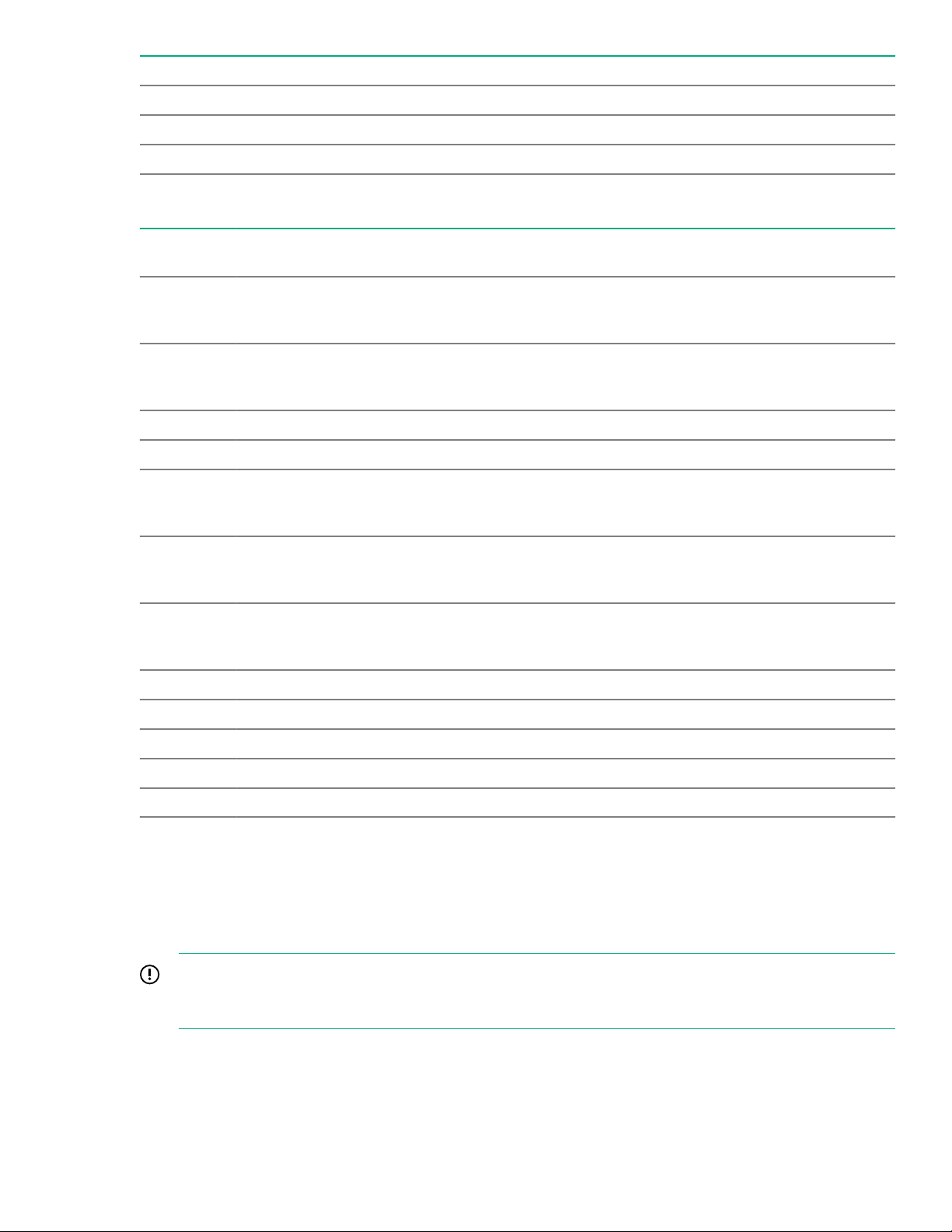
Item Description
18 External USB (located behind the Serial label pull tab)
19 Internal USB 3.0 connector
20 M.2 connectors
System maintenance switch
Position Defa
ult
Function
S11Off Off = HPE iLO security is enabled.
On = HPE iLO security is disabled.
S2 Off Off = System configuration can be changed.
On = System configuration is locked.
S3 Off Reserved
S4 Off Reserved
S51Off Off = Power-on password is enabled.
On = Power-on password is disabled.
S61, 2Off Off = No function
On = Restore default manufacturing settings
S7 Off Off = Set default boot mode to UEFI.
On = Set default boot mode to legacy.
S8 — Reserved
S9 — Reserved
S10 — Reserved
S11 — Reserved
S12 — Reserved
1 You can access the redundant ROM by setting S1, S5, and S6 to On.
2 When the system maintenance switch position 6 is set to the On position, the system is prepared to restore all
configuration settings to their manufacturing defaults.
When the system maintenance switch position 6 is set to the On position and Secure Boot is enabled, some
configurations cannot be restored. For more information, see Secure Boot configuration.
IMPORTANT: Before using the S7 switch to change to Legacy BIOS Boot Mode, be sure the HPE
Dynamic Smart Array B140i Controller is disabled. Do not use the B140i controller when the compute
module is in Legacy BIOS Boot Mode.
Component identification 11
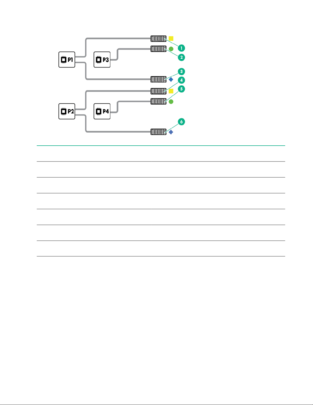
Mezzanine connector definitions
Item Connector
identification
Supported
card types
Fabri
c
Supported ICM bays
1 Mezzanine
connector 1 (M1)
Type C and
Type D
1 ICM 1 and 4
2 Mezzanine
connector 2 (M2)1
Type C and
Type D
2 ICM 2 and 5
3 Mezzanine
connector 3 (M3)
Type C only 3 ICM 3 and 6
4 Mezzanine
connector 4 (M4)
Type C and
Type D
1 ICM 1 and 4
5 Mezzanine
connector 5 (M5)2
Type C and
Type D
2 ICM 2 and 5
6 Mezzanine
connector 6 (M6)
Type C 3 ICM 3 and 6
1 When installing a mezzanine option on mezzanine connector 2, processor 3 must be installed.
2 When installing a mezzanine option on mezzanine connector 5, processor 4 must be installed.
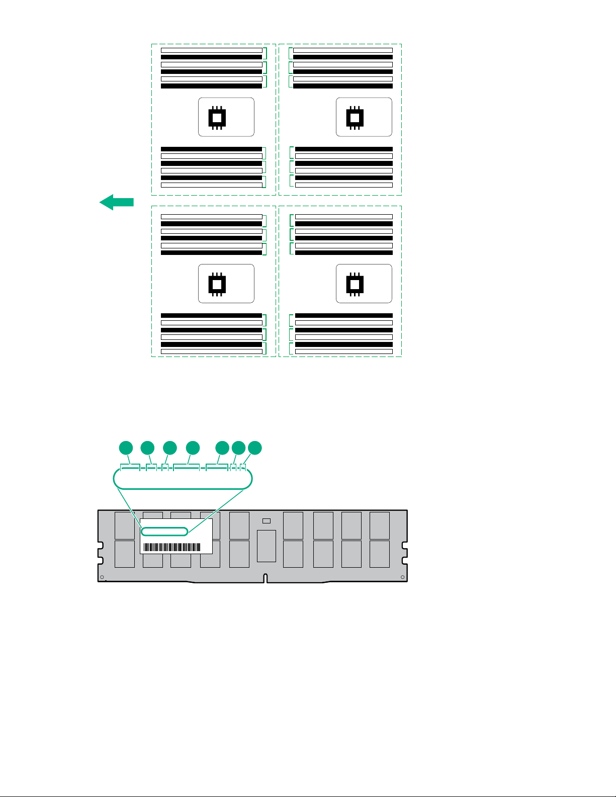
DIMM slot locations
DIMM slots are numbered sequentially (1 through 12) for each processor. The supported AMP modes use the
alpha assignments for population order, and the slot numbers designate the DIMM slot ID for spare
replacement.
The colored slots indicate the slot order within each channel:
• White — First slot of a channel
• Black — Second slot of a channel
The arrow points to the front of the compute module.
12 Component identification
1
2
3
4
5
6
1
2
3
4
5
6
7
8
9
10
11
12
7
8
9
10
11
12
1
2
3
4
5
6
1
2
3
4
5
6
7
8
9
10
11
12
7
8
9
10
11
12
Ch 6 Ch 5 Ch 4
Ch 1 Ch 2 Ch 3
Ch 6 Ch 5 Ch 4
Ch 1 Ch 2 Ch 3 Ch 6 Ch 5 Ch 4
Ch 1 Ch 2 Ch 3
Ch 6 Ch 5 Ch 4
P1
P2
Ch 1 Ch 2 Ch 3
P3
P4
DIMM label identification
To determine DIMM characteristics, see the label attached to the DIMM. The information in this section helps
you to use the label to locate specific information about the DIMM.
8GB 1Rx4 DDR4-2666P-R
8GB 1Rx4 DDR4-2666P-R
1 2 3 4 5 6 7
Component identification 13

Item Description Example
1 Capacity 8 GB
16 GB
32 GB
64 GB
128 GB
2 Rank 1R = Single rank
2R = Dual rank
4R = Quad rank
8R = Octal rank
3 Data width on DRAM x4 = 4-bit
x8 = 8-bit
x16 = 16-bit
4 Memory generation PC4 = DDR4
5 Maximum memory speed 2133 MT/s
2400 MT/s
2666 MT/s
2933 MT/s
6 CAS latency P = CAS 15-15-15
T = CAS 17-17-17
U = CAS 20-18-18
V = CAS 19-19-19 (for RDIMM, LRDIMM)
V = CAS 22-19-19 (for 3DS TSV LRDIMM)
Y = CAS 21-21-21 (for RDIMM, LRDIMM)
Y = CAS 24-21-21 (for 3DS TSV LRDIMM)
7 DIMM type R = RDIMM (registered)
L = LRDIMM (load reduced)
E = Unbuffered ECC (UDIMM)
For more information about product features, specifications, options, configurations, and compatibility, see the
HPE DDR4 SmartMemory QuickSpecs on the Hewlett Packard Enterprise website (http://www.hpe.com/
support/DDR4SmartMemoryQS).
NVDIMM identification
NVDIMM boards are blue instead of green. This change to the color makes it easier to distinguish NVDIMMs
from DIMMs.
To determine NVDIMM characteristics, see the full product description as shown in the following example:
14 Component identification

16GB 1Rx4 NN4-2666V-RZZZ-10
16GB 1Rx4 NN4-2666V-RZZZ-10
1 2 3 74 5 6 8
Item Description Definition
1 Capacity 16 GiB
2 Rank 1R (Single rank)
3 Data width per DRAM chip x4 (4 bit)
4 Memory type NN4=DDR4 NVDIMM-N
5 Maximum memory speed 2667 MT/s
6 Speed grade V (latency 19-19-19)
7 DIMM type RDIMM (registered)
8 Other —
For more information about NVDIMMs, see the product QuickSpecs on the Hewlett Packard Enterprise
website (http://www.hpe.com/info/qs).
NVDIMM 2D Data Matrix barcode
The 2D Data Matrix barcode is on the right side of the NVDIMM label and can be scanned by a cell phone or
other device.
When scanned, the following information from the label can be copied to your cell phone or device:
• (P) is the module part number.
• (L) is the technical details shown on the label.
• (S) is the module serial number.
Example: (P)HMN82GR7AFR4N-VK (L)16GB 1Rx4 NN4-2666V-RZZZ-10(S)80AD-01-1742-11AED5C2
Component identification 15

NVDIMM LED identification
1 2
Item LED description LED color
1 Power LED Green
2 Function LED Blue
NVDIMM-N LED combinations
State Definition NVDIMM-N Power LED
(green)
NVDIMM-N Function LED
(blue)
0 AC power is on (12V rail) but the NVM
controller is not working or not ready.
On Off
1 AC power is on (12V rail) and the NVM
controller is ready.
On On
2 AC power is off or the battery is off (12V rail
off).
Off Off
3 AC power is on (12V rail) or the battery is
on (12V rail) and the NVDIMM-N is active
(backup and restore).
On Flashing
NVDIMM Function LED patterns
For the purpose of this table, the NVDIMM-N LED operates as follows:
• Solid indicates that the LED remains in the on state.
• Flashing indicates that the LED is on for 2 seconds and off for 1 second.
• Fast-flashing indicates that the LED is on for 300 ms and off for 300 ms.
State Definition NVDIMM-N Function LED
0 The restore operation is in progress. Flashing
1 The restore operation is successful. Solid or On
2 Erase is in progress. Flashing
3 The erase operation is successful. Solid or On
4 The NVDIMM-N is armed, and the NVDIMM-N is in
normal operation.
Solid or On
Table Continued
16 Component identification

State Definition NVDIMM-N Function LED
5 The save operation is in progress. Flashing
6 The NVDIMM-N finished saving and battery is still turned
on (12 V still powered).
Solid or On
7 The NVDIMM-N has an internal error or a firmware
update is in progress. For more information about an
NVDIMM-N internal error, see the IML.
Fast-flashing
Component and LED identification for HPE Synergy
hardware
For more information about component and LED identification for HPE Synergy components, see the product-
specific maintenance and service guide or the HPE Synergy 12000 Frame Setup and Installation Guide in the
Hewlett Packard Enterprise Information Library .
Component identification 17

Operations
Powering up the compute module
To power up the compute module, press the Power On/Standby button after the power button LED has turned
amber.
Powering down the compute module
Before powering down the compute module for any upgrade or maintenance procedures, perform a backup of
the system and all data. Then, shut down, as appropriate, applications and operating systems. A successful
shutdown is indicated by the system power LED displaying amber.
IMPORTANT: Always attempt a graceful shutdown before forcing a nongraceful shutdown. Application
data can be lost when performing a nongraceful shutdown of applications and the OS.
Before proceeding, verify the following:
• The compute module is in standby mode by observing that the system power LED is amber.
• The UID LED is not flashing blue.
NOTE:
◦ When the compute module is in standby mode, auxiliary power is still being provided to the system.
◦ If the UID LED is flashing blue, a remote session is in progress.
To power down the compute module, use one of the following methods:
• To perform a graceful shutdown of applications and the OS when powering down the compute module to
standby mode, do one of the following:
◦ Press and release the Power On/Standby button.
◦ Select the Momentary press power off selection in HPE OneView.
◦ Select the Momentary press virtual power button selection in HPE iLO.
• If a graceful shutdown fails to power down the compute module to standby mode when an application or
OS stops responding, force a nongraceful shutdown of applications and the OS. Do one of the following:
◦ Press and hold the Power On/Standby button for more than four seconds.
◦ Select the Press and hold power off selection in HPE OneView.
◦ Select the Press and hold virtual power button selection in HPE iLO.
Removing the compute module
Procedure
1. Identify the proper compute module.
2. Power down the compute module.
18 Operations
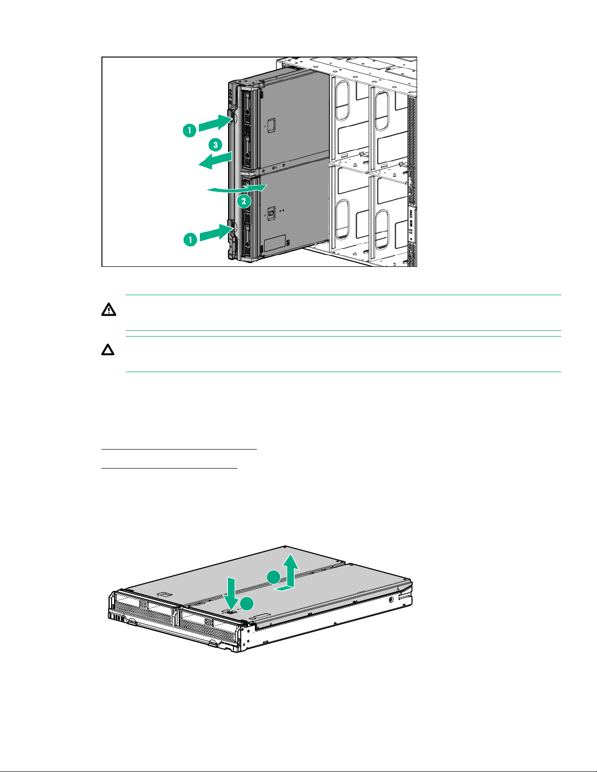
3. Remove the compute module.
4. Place the compute module on a flat, level work surface.
WARNING: To reduce the risk of personal injury from hot surfaces, allow the drives and the internal
system components to cool before touching them.
CAUTION: To prevent damage to electrical components, properly ground the compute module
before beginning any installation procedure. Improper grounding can cause ESD.
Removing the access panel
Procedure
1. Power down the compute module.
2. Remove the compute module.
3. Place the compute module on a flat, level work surface.
4. Press the access panel release button.
5. Slide the access panel towards the rear of the compute module, and then lift the panel to remove it.
1
2
Operations 19
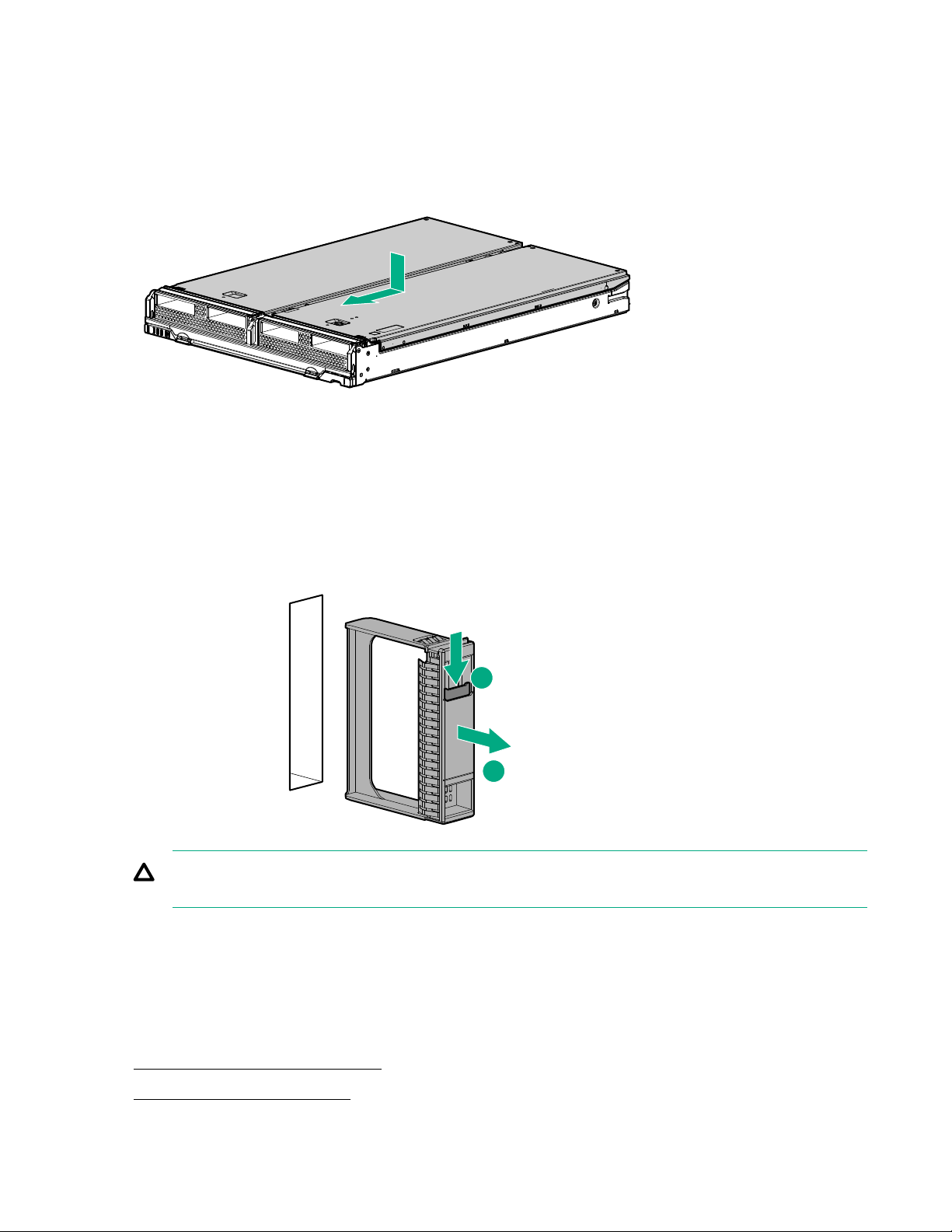
Installing the access panel
Procedure
1. Place the access panel on top of the compute module.
2. Slide the access panel forward until it clicks into place.
Removing and replacing a drive blank
Procedure
1. Press the drive release button.
2. Remove the drive.
1
2
CAUTION: To prevent improper cooling and thermal damage, do not operate the compute module
unless all bays are populated with either a component or a blank.
To replace the component, reverse the removal procedure.
Removing the DIMM baffle
Procedure
1. Power down the compute module.
2. Remove the compute module.
20 Operations
Table of contents
Other Hewlett Packard Enterprise Control Unit manuals


Popular Control Unit manuals by other brands


PIETRO FIORENTINI
PIETRO FIORENTINI SBC 782 Technical manual

resideo
resideo Braukmann D160S installation instructions

Guntermann & Drunck
Guntermann & Drunck CATpro2-DVI-Audio-UC-USB installation guide

Lafayette Instrument
Lafayette Instrument MMT User instructions

ELCOS
ELCOS CIM-130 Instruction and user's manual

National Instruments
National Instruments MXI Series Getting started