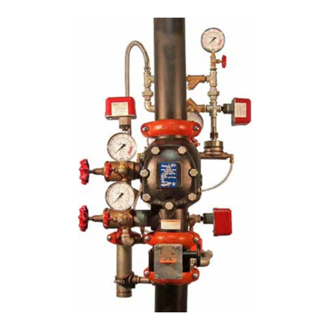
Victaulic FireLock 758-LPA Series User manual

1
Series 758-LPA FireLock
™
Actuated System Valve
With Deluge Trim and
Series 776 Low-Pressure Actuator
Installation, Maintenance, and
Testing Manual
Failure to follow instructions and warnings can result in serious injury.
• Always read and understand all installation instructions before attempting assembly of Vic-
taulic piping products.
• Always wear safety glasses and foot protection.
• Failure to do so could result in serious personal injury, property damage, and/or valve
leakage.
If you need additional copies of this manual, or if you have any questions about the safe op-
eration of this valve, contact Victaulic Company, P.O. Box 31, Easton, PA 18044-0031, USA,
Telephone: 001-610-559-3300.
R
Hang these instructions
in a visible location on the
installed valve for easy
future reference.
DISCONTINUED PRODUCT

2
Table of Contents . . . . . . . . . . . . . . . . . . . . . . . . . . . . . . . . . .2
Important Information . . . . . . . . . . . . . . . . . . . . . . . . . . . . . .2
Installer Safety Instructions . . . . . . . . . . . . . . . . . . . . . . . . . .3
Introduction. . . . . . . . . . . . . . . . . . . . . . . . . . . . . . . . . . . . . . .4
Exploded View Drawings. . . . . . . . . . . . . . . . . . . . . . . . . . . .4
Dimensions . . . . . . . . . . . . . . . . . . . . . . . . . . . . . . . . . . . . . . .5
Series 776 Low-Pressure Actuator Operation . . . . . . . . . . .6
Series 776 Cutaway Drawing . . . . . . . . . . . . . . . . . . . . . . . .6
Pilot Line Heights . . . . . . . . . . . . . . . . . . . . . . . . . . . . . . . . . .7
Installation. . . . . . . . . . . . . . . . . . . . . . . . . . . . . . . . . . . . . . .10
Important Settings . . . . . . . . . . . . . . . . . . . . . . . . . . . . . . . .10
Air Supply Design. . . . . . . . . . . . . . . . . . . . . . . . . . . . . . . . .11
Placing the System in Service. . . . . . . . . . . . . . . . . . . . . . .12
Inspection and Tests. . . . . . . . . . . . . . . . . . . . . . . . . . . . . . 14
Weekly Inspection. . . . . . . . . . . . . . . . . . . . . . . . . . . . . . 14
Required Tests . . . . . . . . . . . . . . . . . . . . . . . . . . . . . . . . 15
Trip Test. . . . . . . . . . . . . . . . . . . . . . . . . . . . . . . . . . . . . . 16
Maintenance . . . . . . . . . . . . . . . . . . . . . . . . . . . . . . . . . . . . 17
Removing the Rubber Clapper Facing . . . . . . . . . . . . . 18
Installing the Rubber Clapper Seal . . . . . . . . . . . . . . . . 19
Removing the Clapper Assembly . . . . . . . . . . . . . . . . . 18
Installing the Clapper . . . . . . . . . . . . . . . . . . . . . . . . . . . 20
Removing the Actuator Piston . . . . . . . . . . . . . . . . . . . 21
Installing the Cover Plate . . . . . . . . . . . . . . . . . . . . . . . . 21
Troubleshooting. . . . . . . . . . . . . . . . . . . . . . . . . . . . . . . . . . 22
Warranty. . . . . . . . . . . . . . . . . . . . . . . . . . . . . . . . . . . . . . . . 22
Facilities Locations . . . . . . . . . . . . . . . . . . . . . . . . . . . . . . B/C
TABLE OF CONTENTS
Important Information
Definitions for identifying the various hazard levels shown on warning labels, or to indicate proper safety procedures in this
instruction manual, are provided below.
This safety alert symbol indicates important safety messages on warning labels in this instruction manual. When
you see this symbol, be alert to the possibility of personal injury. Carefully read and fully understand the message
that follows.
• This product must be installed by an experienced, trained installer, in accordance with the instructions provided
with each valve. These instructions contain important information.
Failure to follow these instructions may result in serious personal injury, property damage, or valve leakage.
If you need additional copies of this literature, or if you have any questions about the safe installation and use of
this device, contact Victaulic Company, P.O. Box 31, Easton, PA 18044-0031 USA, Telephone: 001-610-559-3300.
NOTICE
The use of the word “NOTICE” signifies special instructions, which are
important, but not related to hazards.
The use of the word “CAUTION” signifies possible hazards or unsafe
practices, which could result in minor personal injury, product, and/or
property damage if instructions, including precautions, are not followed.
The use of the word “WARNING” signifies the presence of hazards or
unsafe practices, which could result in severe personal injury if instruc-
tions, including recommended precautions, are not followed.
® Registered Trademark of Victaulic © Copyright 2000 Victaulic Printed in U.S.A.
DISCONTINUED PRODUCT

3
INSTALLER SAFETY INSTRUCTIONS
GENERAL
1.
Read and understand this manual before proceeding with installation, maintenance, and testing of the Victaulic
Fire Protection Device.
This product must be installed by an experienced, trained installer, in accordance with instructions provided
with each valve. These instructions contain important information. Additional copies of these valve installation instructions are available
at no charge. If you need additional copies, or if you have any questions about the safe installation and use of this device, contact
Victaulic Company, P.O. Box 31, Easton, PA 18044-0031 USA, Telephone: 001-610-559-3300.
2.
Use only recommended accessories.
Use of improper accessories or equipment in conjunction with these fire protection
devices may result in improper operation of the system.
3.
Avoid dangerous environments.
If utilizing electrically-powered tools for installation, be sure that the area is free of moisture or
wetness, which could create an unsafe condition. Keep work area well illuminated. Allow sufficient space for the device, trim, and
accessories, plus allow sufficient space to accommodate proper installation.
4.
Prevent back injury.
Larger and pre-trimmed valves may be sufficiently heavy. Installation may require more than one person, or
mechanical lifting equipment, to position the unit properly. Utilize proper lifting techniques and be aware of the possible need for
assistance.
5.
Inspect the equipment.
Be sure all parts are included, and that you have all necessary tools available to install the device properly.
6.
Wear safety glasses, hardhat, and safety footwear.
Always practice safety first.
7.
Watch for pinch points.
Do not put fingers under the valve base where they could be pinched by the weight of the valve. Exercise
caution around spring-loaded components, such as the swing clapper, clapper locking latch, and piston spring assembly.
8.
Keep work area clean.
Cluttered areas, benches, and slippery floors invite accidents.
9.
Wear ear protection.
Your hearing should be protected if exposed to long periods of very noisy job-site or shop operations.
10.
Keep visitors away.
All visitors should be kept a safe distance away from the work area.
MAINTENANCE AND TESTING
1.
Always notify the authority having jurisdiction.
Any system service that requires taking a control valve or alarm valve out of
service may eliminate the fire protection provided by the system. Prior to servicing or testing the system, notify the authority having
jurisdiction of the operation being performed.
2.
Always depressurize the system before attempting any maintenance work.
Water under pressure, trapped air, or system
air pressure may be present and must be fully deactivated and depressurized prior to proceeding with any service work, disassembly, or
removal of any parts.
3.
Follow NFPA requirements for system testing and inspection schedules.
The authority having jurisdiction may mandate
more frequent or additional tests or inspections.
4.
Keep system free from freezing (wet systems), foreign matter, or corrosive atmospheres.
Any condition, which might
degrade the system or adversely affect system performance, must be avoided.
5.
Depressurize valve before removing cover plate bolts.
The cover may blow off if these bolts are removed while the valve is
pressurized.
• This product must be installed by an experienced, trained installer, in accordance with the instructions provided
with each valve. These instructions contain important information.
Failure to follow these instructions may result in serious personal injury, property damage, and/or valve leakage.
If you need additional copies of this valve installation instructions, or if you have any questions about the safe in-
stallation and use of this device, contact Victaulic Company, P.O. Box 31, Easton, PA 18044-0031 USA, Telephone:
001-610-559-3300.
• Piping systems must always be depressurized and drained before attempting disassembly and/or removal of any
Victaulic piping products.
Failure to do so could result in serious personal injury, property damage, and/or valve leakage.
DISCONTINUED PRODUCT

4
The following procedures are a guide for the proper assembly of Victaulic Series 758-LPA Actuated
System Valves with Deluge Trim.
These instructions are based on pipe that is prepared and grooved properly in accordance with the
latest published Victaulic grooving specifications.
INTRODUCTION
• Always read and understand all installation
instructions before attempting assembly of
Victaulic piping products.
Failure to do so could result in serious per-
sonal injury, property damage, and/or valve
leakage.
• Piping systems must always be de-
pressurized and drained before at-
tempting disassembly and removal of
any Victaulic piping products.
Failure to do so could result in serious
personal injury, property damage, and/or
valve leakage.
Clapper
Latch
Piston
Assembly
Alarm
Outlet
Alarm
Test Seat
Seal
"WEEP" Hole
DISCONTINUED PRODUCT

5
DIMENSIONS
10.35-1B
VALVE
SIZE
Nominal
Inches
Actual mm
Dimensions
Inches/
mm
Aprx. Weight Each
Lbs./
kg
Without Trim With Trim
A B C D E F G H I Flanged Grooved Flanged Grooved
GROOVED
✕
GROOVED
1
¹⁄₂
9.00 21.00 13.00 18.00 13.00 10.00 7.00 4.00 4.00 – 16.7 – 43.0
48,3 228,6 533,4 330,2 457,0 330,2 254,0 177,8 101,6 101,6 – 7,6 – 19,5
2 9.00 21.00 13.00 18.00 13.00 10.00 7.00 4.00 4.00 – 17.0 – 43.0
60,3 228,6 533,4 330,2 457,0 330,2 254,0 177,8 101,6 101,6 – 7,7 – 19,5
2
¹⁄₂
12.50 21.00 14.00 20.00 15.50 11.50 7.50 5.00 5.00 – 41.2 – 65.0
73,0 317,5 533,4 355,6 508,0 393,7 292,1 190,5 127,0 127,0 – 18,7 – 29,5
76,1 mm 12.50 21.00 14.00 20.00 15.50 11.50 7.50 5.00 5.00 – 41.2 – 65.0
317,5 533,4 355,6 508,0 393,7 292,1 190,5 127,0 127,0 – 18,7 – 29,5
3 12.50 21.00 14.00 20.00 15.50 11.50 7.50 5.00 5.00 – 42.1 – 65.0
88,9 317,5 533,4 355,6 508,0 393,7 292,1 190,5 127,0 127,0 – 19,1 – 29,5
4 15.00 20.00 15.00 21.00 14.00 12.00 8.00 9.00 6.00 – 55.0 – 95.0
114,3 381,0 508,0 381,0 533,4 355,6 304,8 203,2 228,6 152,4 – 24,9 – 43,1
6 16.00 21.10 16.00 22.00 14.00 12.00 8.50 7.00 7.00 – 73.0 – 115.0
168,3 406,4 535,9 406,4 558,8 355,6 304,8 215,9 177,8 177,8 – 33,1 – 52,2
165,1 mm 16.00 21.10 16.00 22.00 14.00 12.00 8.50 7.00 7.00 – 73.0 – 115.0
406,4 535,9 406,4 558,8 355,6 304,8 215,9 177,8 177,8 – 33,1 – 52,2
8 18.00 17.50 16.00 23.00 16.00 12.00 14.00 9.50 7.00 – 142.0 – 182.0
219,1 457,0 444,5 406,4 584,0 406,4 304,8 355,6 241,3 177,8 – 64,4 – 82,6
GROOVED
✕
FLANGED
4 16.00 20.00 15.00 21.00 14.00 12.00 8.00 9.00 6.00 65.0 – 105.0 –
114,3 406,4 508,0 355,6 533,4 355,6 304,8 203,2 228,6 152,4 29,5 – 47,6 –
6 17.00 21.10 16.00 22.00 14.00 12.00 8.50 7.00 7.00 83.0 – 125.0 –
168,3 431,8 535,9 406,4 558,8 355,6 304,8 215,9 177,8 177,8 37,6 – 56,7 –
165,1 mm 17.00 21.10 16.00 22.00 14.00 12.00 8.50 7.00 7.00 83.0 – 125.0 –
431,8 535,9 406,4 558,8 355,6 304,8 215,9 177,8 177,8 37,6 – 56,7 –
8 19.30 18.00 16.00 23.00 16.00 12.00 14.00 9.50 7.00 155.0 – 195.0 –
219,1 490,2 457,0 406,4 584,0 406,4 304,8 355,6 241,3 177,8 70,3 – 88,5 –
EF
H I
DAB
C
G
DISCONTINUED PRODUCT

6
The Series 776 Low-Pressure Actuator is located on the
trim of pneumatically released Series 758-LPA Actuated
Valves and acts as the trigger for these systems.
Diaphragms separate the low-pressure actuator into three
chambers. The upper air chamber controls the activation,
while the middle and lower chambers act as the water
valve.
During charging, the system feeds air into the upper cham-
ber of the low-pressure actuator. As you pull up on the
auto vent’s knob, which is located on the low-pressure
actuator, it manually sets the upper chamber. The air pres-
sure in the upper chamber holds the auto vent closed,
while it exerts force on the water seal of the middle cham-
ber.
When you open the piston charge line of the control valve,
water enters the lower chamber of the low-pressure actua-
tor. The water entering the low-pressure actuator flows to
the middle chamber through a hole in the lower diaphragm
assembly, which is pressurized by the system air pressure
in the upper chamber.
SERIES 776 LOW-PRESSURE ACTUATOR OPERATION
Auto Vent
Assembly
Upper
Chamber
Diaphragm
Shield
Spring Pin
Lower ChamberLower Diaphragm
Assembly
Middle
Chamber
Wave
Spring
Upper Diaphragm
Assembly
Since the area of the lower diaphragm (exposed to the mid-
dle chamber’s water pressure) is greater than the area of
the lower chamber, the lower chamber seals off. No water
flows to the low-pressure actuator’s outlet, and the supply
water pressure creates the water seal.
When the system air pressure decays to 6.5 psi (45 kPa),
the force exerted by the compression spring in the auto
vent is greater than the force exerted by the air in the
upper chamber. The auto vent opens and all air pressure in
the upper chamber evacuates. The upper diaphragm then
releases the water pressure in the low-pressure actuator’s
middle chamber, which allows the lower diaphragm to lift
and water to flow from the low-pressure actuator’s inlet to
the outlet. This water flow releases water pressure from
the control valve’s piston, thus allowing the piston to
retract. The control valve’s clapper opens, and water flows
into the sprinkler system.
DISCONTINUED PRODUCT

7
WET PILOT LINE CHARTS
0.0
20.0
40.0
60.0
80.0
100.0
120.0
140.0
10 25 50 100 200 300 400 500 1000
2¹⁄₂ - 3" & 76,1 mm
MAXIMUM ALLOWABLE PILOT LINE HEIGHTS FOR SPECIFIC EQUIVALENT LENGTHS
Length of Pipe (ft.)
Maximum Pilot Line Height (ft.)
280 PSI
260 PSI
240 PSI
220 PSI
200 PSI 180 PSI
160 PSI
140 PSI
120 PSI
100 PSI
80 PSI
60 PSI
40 PSI
20 PSI
300 PSI
Heights are based on ¹⁄₂" schedule 40 pipe and a ¹⁄₂" sprinkler head.
0.0
50.0
100.0
150.0
200.0
250.0
10 25 50 100 200 300 400 500 1000
1¹⁄₂ - 2"
MAXIMUM ALLOWABLE PILOT LINE HEIGHTS FOR SPECIFIC EQUIVALENT LENGTHS
Length of Pipe (ft.)
Maximum Pilot Line Height (ft.)
280 PSI
260 PSI
240 PSI
220 PSI
200 PSI
180 PSI
160 PSI
140 PSI
120 PSI
100 PSI
80 PSI
60 PSI
40 PSI 20 PSI
300 PSI
DISCONTINUED PRODUCT

8
WET PILOT LINE CHARTS
0.0
20.0
40.0
60.0
80.0
100.0
120.0
140.0
10 25 50 100 200 300 400 500 1000
4"
MAXIMUM ALLOWABLE PILOT LINE HEIGHTS FOR SPECIFIC EQUIVALENT LENGTHS
Length of Pipe (ft.)
Maximum Pilot Line Height (ft.)
300 PSI
280 PSI
260 PSI
240 PSI
220 PSI
200 PSI
180 PSI
160 PSI
140 PSI
120 PSI
100 PSI
80 PSI
60 PSI
40 PSI
20 PSI
0.0
50.0
100.0
150.0
200.0
250.0
10 25 50 100 200 300 400 500 1000
6" & 165,1 mm
MAXIMUM ALLOWABLE PILOT LINE HEIGHTS FOR SPECIFIC EQUIVALENT LENGTHS
Length of Pipe (ft.)
Maximum Pilot Line Height (ft.)
300 PSI
280 PSI
260 PSI
240 PSI
220 PSI
200 PSI
180 PSI
160 PSI
140 PSI
120 PSI
100 PSI
80 PSI
60 PSI
40 PSI 20 PSI
Heights are based on ¹⁄₂" schedule 40 pipe and a ¹⁄₂" sprinkler head.
DISCONTINUED PRODUCT

9
WET PILOT LINE CHARTS
Heights are based on ¹⁄₂" schedule 40 pipe and a ¹⁄₂" sprinkler head.
0.0
50.0
100.0
150.0
250.0
300.0
10 25 50 100 200 300 400 500 1000
8"
MAXIMUM ALLOWABLE WET PILOT LINE HEIGHTS FOR SPECIFIC EQUIVALENT LENGTHS
Length of Pipe (ft.)
Maximum Pilot Line Height (ft.)
200.0
225 PSI
200 PSI
180 PSI
160 PSI
140 PSI
120 PSI
100 PSI
80 PSI
60 PSI
40 PSI
20 PSI
DISCONTINUED PRODUCT

10
INSTALLATION
For proper operation and approval, you must install the
valve in accordance with the trim diagrams for the Series
758-LPA Deluge Valve. Victaulic provides specific trim
drawings for pneumatic, hydraulic, and electric release
installations.
The Series 758-LPA Deluge Valve must
NOT
be located in
an area that is subject to freezing temperatures. In addi-
tion, the valve must
NOT
be located in an area where
physical damage may occur. It is the owner’s responsibility
to confirm material compatibility of the Series 758-LPA Del-
uge Valve, trim, and associated accessories when a corro-
sive atmosphere or contaminated water is present.
Air or nitrogen supply to the deluge piping system must be
clean, dry, and oil free. Automatic air supplies must be reg-
ulated, restricted, and continuous. Victaulic recommends
the installation of an air maintenance device on any system
with an automatic air supply.
When used with a water motor alarm, configure the valve
with an uninterrupted, low-pressure alarm mounted to the
valve’s piston.
Prior to installing the valve, flush the water supply piping
thoroughly in order to ensure that no foreign objects are
present.
Install the Series 758-LPA Deluge Valve in the vertical posi-
tion with the arrow on the body pointing upward.
1.
Confirm that all required drawings and data for the
installation of the valve are available.
2.
Remove all plastic caps from the valve.
3.
Remove the foam spacer shipped with the valve. This
spacer holds the clapper shut during shipment.
4.
For valves 3" (88,9 mm) or smaller, it is necessary to
remove the piston assembly when trimming the valve.
4a.
Unscrew the piston from the valve’s body.
4b.
Note the position of the o-ring. This o-ring must be in
the same position when you reassemble the piston.
4c.
Install the trim to the back of the valve.
4d. Reassemble the piston, making sure that the o-ring is
positioned properly and that the piston rod and the latch
engage properly. It may be necessary to rotate the latch
inward (toward the valve body’s center) to ensure proper
alignment.
4e. Tighten the piston until you achieve metal to metal
contact with the valve body.
5. Apply a small amount of pipe joint compound or Teflon*
pipe tape to the external threads of all threaded pipe con-
nections. Be careful not to get any tape, compound, or
other foreign substance into the valve or the inside of any
nipples or valve openings.
6. Make sure the trim drawing matches the system’s
requirements. Install the Victaulic Series 758-LPA Deluge
Valve in accordance with the applicable trim drawings.
7S. Provide an uninterrupted source of water from
upstream of the main control valve to supply pressure to
the piston charge line prior to opening the main control
valve.
IMPORTANT SETTINGS
Pneumatic Release Systems
1. For pneumatic release systems used with a Series 776
Low-Pressure Actuator and a base-mounted compressor,
supply an air pressure between 9 psi (62 kPa) minimum
and 14 psi (97 kPa) maximum. The air pressures in this
chart are the “On” or “Low” settings for the pressure switch
on the compressor.
2. Set the air supervisory switch to activate at 8 psi (55
kPa).
3. Wire the air supervisory switch to activate a low pres-
sure alarm signal. A high pressure alarm may also be
required by the authority having jurisdiction.
• Before installing the valve, you must remove the foam
spacer that holds the clapper shut during shipment.
Failure to follow this instruction could result in serious per-
sonal injury, property damage, valve leakage, and/or valve
failure.
• Make sure you reassemble and install the piston correctly
according to the instructions contained in this manual.
Failure to follow these instructions could result in serious
personal injury, valve malfunctioning, and/or property dam-
age.
• Make sure that no foreign material gets into the valve’s trim.
Failure to follow this instruction could result in improper valve operation.
*Teflon is a registered trademark of I.E. Dupont de Nemours
DISCONTINUED PRODUCT

11
Alarm Pressure Switch
1. Set the alarm pressure switch to activate on a pressure
rise of 4 - 8 psi (25 - 55 kPa). Wire the alarm pressure switch
to activate a water flow alarm.
AIR SUPPLY DESIGN
Important Information
1. You must use an air regulator with Series 758D-LPA Del-
uge Valves that contain a Series 776 Low-Pressure Actua-
tor.
2. The recommended air pressures in the above chart
apply to valves using a Series 776 Low-Pressure Actuator
between 9 psi (62 kPa) minimum and 14 psi (97 kPa) maxi-
mum.
3. Size the air supply system to establish the required air
pressure in the system within 30 minutes. Regulate,
restrict, and maintain the air supply automatically.
4. You must regulate the air pressure to the proper system
air pressure. Air pressure differing from the required sys-
tem air pressure could adversely affect the operation of the
system.
5. You must restrict the air supply in order to ensure that
the air being exhausted from an open head or manual
release valve is not replaced by the air supply system as
fast as it is being exhausted.
6. Recommended practice is to provide an inspector’s test
connection for the release system. Equip the inspector’s
test connection with a ball valve (normally locked closed),
which can be opened in order to simulate the actuation of a
release device.
7. Locate the test connection at the highest, most hydrau-
lically demanding location in the release system. The test
connection should terminate with an orifice equal to the
smallest orifice in the releasing system. You can use an
inspector’s test connection in order to confirm that the air
or water supply systems are not supplying pressure at a
rate faster than the releasing device can exhaust pressure.
Compressor Requirements for the
Series 776 Low-Pressure Actuator
Systems Using Shop Air or a
Tank-Mounted Compressor
1. To provide the greatest amount of protection in the
event that a compressor becomes inoperative, use a tank-
mounted compressor. With a properly sized tank, air can
be supplied continuously to the sprinkler system for an
extended time, even without an operating compressor.
• Properly size and build the air supply system according
to the instructions below.
Failure to follow this instruction could result in serious
personal injury, property damage, and/or valve leakage.
AIR PRESSURE –PSI
MAXIMUM WATER SUPPLY PRESSURE - PSI (Peak)
RECOMMENDED AIR PRESSURE FOR DRY AND PNEUMATIC ACTUATED SYSTEMS
USING A SERIES 776 LOW-PRESSURE ACTUATOR
60
50
40
30
20
10
0
5 10 15 20 25 50 75 100 125 150 175 200 225 250 275 300
0
0.5
1
1.5
2
2.5
3
0 100 200 300 400 500 600 700 800 900 100011001200130014001500
REQUIRED FLOW RATE (CFM)
SYSTEM CAPACITY (GAL.)
SERIES 776 COMPRESSOR REQUIREMENTS
DISCONTINUED PRODUCT

12
2. You must use Victaulic Company’s Air Maintenance
Trim Assembly (AMTA) with a tank-mounted compressor
or shop air (refer to drawing above). The AMTA provides
the proper air regulation to the sprinkler system, which will
ensure the proper operation of the fire safety valve.
3. Set the air regulator to 10 psi (69 kPa).
Systems Using a Riser or
Base-Mounted Air Compressor
1. When a riser or base-mounted air compressor supplies
air to a system using a Series 776 Low-Pressure Actuator, it
is not necessary to use the air maintenance trim assembly
with the air regulator. In this circumstance, the airline of
the compressor connects to the valve’s trim at the fitting
where the air maintenance trim is normally installed.
2. When the valve is used with this setup, it is the engi-
neer’s/system designer’s responsibility to size the com-
pressor so that it brings the entire system to required
pressure within 30 minutes.
3. The engineer/system designer must not oversize the
compressor to provide more airflow because it will slow
down, or possibly prevent, the operation of the valve.
4. A base-mounted compressor does not provide any
backup air to the system. Therefore, the system requires
continuous service (24 hours per day, 7 days per week) in
order to prevent the valve from false tripping due to a loss
of air pressure.
5. Due to the large on/off differential available on pressure
switches that control base-mounted compressors, you
must adjust the compressor pressure switch so that the
“ON” contact of the pressure switch is set to 9 psi (62 kPa)
minimum. Set the “OFF” contact of the pressure switch to
14 psi (97 kPa) maximum.
Pilot Line Heights
1. Determine wet pilot line heights from the graphs on
pages 7, 8, and 9. Heights are based on ¹⁄₂" schedule 40
pipe and a ¹⁄₂" sprinkler head.
PLACING THE SYSTEM
IN SERVICE
When the deluge system is ready to be placed in service,
verify that all equipment is heated and protected properly
from freezing temperatures and physical damage.
1. Open the system drain valve located above the clapper.
Confirm that the system is drained.
2. Confirm that the system drains are shut.
3. For pneumatic systems: Open the fast fill ball valve
on the air maintenance device. Fill the pilot system to the
appropriate air pressure for the typical water supply pres-
sure in the area. NOTE: Confirm that the pilot system is
charging by observing the air pressure gauge. If the gauge
is not showing an increase in air pressure, there is a leak or
an open line in the release pilot system.
3a. While the system is charging, it may be necessary to
remove the protective cap on the Series 776 and pull up on
the auto vent knob. Confirm that this knob remains in this
“up” position. Replace the protective cap.
•Opening the main control valve of the water supply will cause water to flow from all
open system openings.
Doing so may cause personal injury and/or property damage.
•Make sure you always replace the protective cap over the auto vent knob of the Se-
ries 776 to avoid accidental contact. Hitting the auto vent knob will cause the valve
to trip.
Failure to follow this instruction could result in serious personal injury and/or property
damage.
DISCONTINUED PRODUCT

13
4. For pneumatic systems: Once the pilot system air
pressure has been established, close the fast fill ball valve
and open the slow fill ball valve. Confirm that the air regula-
tor is set to 10 psi (69 kPa).
4a. For pneumatic systems: Observe the system’s air
pressure over a 24 hour period to confirm system integrity.
If there is degradation in the system’s air pressure, find the
leaks and correct. NFPA requires less than 2 psi leakage in
24 hours.
5. Open the piston charge line ball valve.
SERIES 749 AUTO DRAIN ASSEMBLY
5a. Remove the cap from the Series 746 Auto Drain. Pull
on the auto drain set screw until the auto drain is set
(approximately 10 psi). Replace the protective cap on the
auto drain.
5b. Allow the system to pressurize. Confirm that water
pressure is established. The piston is now actuated, and
the clapper will now be set.
6. Open the water supply drain valve. This is the drain
located below the clapper.
7. Slowly open the main water supply control valve until a
steady flow of water is flowing from the open water supply
drain valve.
SLOW FILL
BALL VALVE
Cap
Set Screw
Seal
Compression
Fitting
Drain
Hose
Body
Spring
Stem
•Make sure you always replace the protective cap over the auto drain set screw to
avoid accidental contact. Hitting the set screw will cause the valve to trip.
Failure to follow this instruction could cause serious personal injury and/or property
damage.
•Opening the main control valve of the water supply will cause water to flow from all
open system openings.
Doing so may cause personal injury and/or property damage.
DISCONTINUED PRODUCT

14
8. Once a steady flow of water is observed, close the water
supply drain valve slowly. Confirm that there is no leakage
from the ball drip. If water is flowing from the ball drip,
close the main water supply valve and start over at step 1.
9. Fully open the main water supply control valve.
10. Record the system air pressures, if applicable, and the
water supply pressures.
11. Make sure all valves are in their normal operating
positions.
12. Notify the authority having jurisdiction, remote station
monitors, and those in the affected area that the valve and
system are in service.
INSPECTION AND TESTS
WEEKLY INSPECTION
Victaulic recommends that you perform a visual inspection
of the deluge system and the trim on a weekly basis. If the
deluge system is equipped with a low-pressure alarm,
monthly inspections may be sufficient, depending on
requirements of the local authority having jurisdiction. Ver-
ify these requirements by contacting the authority having
jurisdiction in your affected area.
1. Observe and record the system pressures. Confirm that
the water supply pressure is in the range of normal pres-
sures observed in the area. Significant loss in supply pres-
sure could indicate an adverse condition in the water
supply.
2. Confirm that there is no leakage from the intermediate
chamber of the valve. No water should flow from the ball
drip.
3. Check for mechanical damage or corrosion. If found,
repair the affected parts.
4. Confirm that the valve and trim are not subject to freez-
ing conditions.
5. Verify that all system valves are in their normal operat-
ing position.
The owner is responsible for maintaining the deluge system in proper operating condi-
tion.
•It is important that you inspect and test this deluge system regularly, according to
proper procedures.
•The Victaulic Series 758 Deluge Valve and trim must not be exposed to foreign mat-
ter, corrosive atmospheres, freezing conditions, contaminated water supplies, or
any other condition that could impair the proper operation of the system.
•You must modify the frequency of inspections in the presence of any environmental
conditions that could degrade the system’s operation.
•The National Fire Protection Association Pamphlet, which describes the care and
maintenance of sprinkler systems, outlines the minimum requirements for tests and
inspections.
•In addition, the authority having jurisdiction may have maintenance, inspection, and
test requirements that must be followed.
Failure to follow these instructions may result in serious personal injury, property dam-
age, and/or system failure.
•Any system service that requires taking the control valve or deluge
system out of service may eliminate the fire protection provided by
the system. Prior to servicing or testing the system, notify the au-
thority having jurisdiction of the operation being performed. Consid-
eration of a fire patrol should be given in the affected areas.
Failure to do so could result in serious personal injury and/or property
damage.
DISCONTINUED PRODUCT

15
REQUIRED TESTS
Main Drain Test
Perform the main drain test on a frequency required by the
current NFPA-25 code. The authority having jurisdiction in
your area may require that you perform these tests on a
more frequent basis. Verify these requirements by contact-
ing the authority having jurisdiction in your affected area.
1. Inform the authority having jurisdiction, remote station
alarms monitor, and anyone in the affected area that the
test will be performed.
2. Perform and record as per the monthly visual inspection.
3. Confirm that sufficient drainage is in place for a full flow
drain test.
4. Record the water supply pressure and the pilot system
air pressure.
5. Verify that the intermediate chamber of the deluge sys-
tem is dry. No water should flow from the ball drip.
6. For pneumatic systems, verify that the deluge system is
pressurized at the proper air pressure for the local water
supply pressures.
7. Fully open the water supply drain valve located below
the clapper.
8. With the water supply drain fully open, record the water
supply pressure (record as the residual pressure).
9. Close the water supply drain valve slowly.
10. Compare the new residual pressure reading with the
residual pressure readings taken in previous main drain
tests. If there is a degradation in the residual water supply
readings, take the appropriate measures to restore proper
water supply pressure.
11. Record the water pressures established after closing
the main drain. Confirm that all ball valves are in their
proper operating positions.
12. Notify the authority having jurisdiction, remote station
alarm monitors, and those in the affected area that the
valve has been placed back in service. Provide test results,
as required, to the authority having jurisdiction.
Water Flow Alarm Test
Perform the water flow alarm test on a frequency required
by the current NFPA-25 code. The authority having juris-
diction in your area may require that you perform these
tests on a more frequent basis. Verify these requirements
by contacting the authority having jurisdiction in your
affected area.
1. Notify the authority having jurisdiction and those in the
affected test area that a test is in progress.
2. Fully open the main water supply drain and flush the
water supply of any contaminants.
3. Close the main water supply drain.
NOTE: Photo taken of alarm valve for clarity of ball valve’s location.
4. Close the alarm line ball valve.
NOTE: Photo taken of alarm valve for clarity of ball valve’s location.
5. Open the alarm test ball valve in the deluge system trim.
Confirm that mechanical and electric alarms provided are
activated, and that remote monitoring stations, if provided,
receive an alarm signal.
6. After proper operation of all alarms is confirmed, close
the alarm test ball valve. Open the ¹⁄₄" alarm drain ball valve
on the drain line located below the restrictor. Verify that all
alarms stop sounding, that the water motor alarm has
drained, and that remote station alarms reset properly.
ALARM LINE
BALL VALVE
ALARMTEST
BALL VALVE
DISCONTINUED PRODUCT

16
7. Confirm that the alarm line ball valve in the deluge sys-
tem trim is open. Confirm that the alarm test ball valve and
the alarm drain ball valve are closed.
8. Verify that the intermediate chamber of the deluge sys-
tem is dry. No water should flow from the ball drip.
9. Notify the authority having jurisdiction, remote station
alarm monitors, and those in the affected area that the
valve has been placed back in service.
Water Level and Low Air Alarm Test
(Pneumatic Systems)
Perform the water level and low air alarm tests on a fre-
quency required by the current NFPA-25 code. The author-
ity having jurisdiction in your area may require that you
perform these tests on a more frequent basis. Verify these
requirements by contacting the authority having jurisdic-
tion in your affected area.
1. Notify the authority having jurisdiction and those in the
affected area that the test will be in progress.
2. Open the main water supply drain to flush any contami-
nants that may have collected.
3. Close the water supply control valve.
4. Open the inspector’s test valve. Record the system air
pressure at which the low air alarm activates.
5. Close the inspector’s test valve.
6. Perform Steps 4 - 12 of “Placing the System in Service.”
TRIP TEST
Partial flow tests are used to confirm the proper operation
of the valve. The partial flow test does not confirm the oper-
ation of the full system.
Full flow testing allows the full flow of water into the sprin-
kler system, and it must be done in warm weather when
there is no chance of freezing conditions.
The frequency of inspections may vary due to environmen-
tal conditions around the valve. For minimum maintenance
and inspection requirements, refer to the NFPA pamphlet
describing the care and maintenance of sprinkler systems.
More frequent full and partial flow tests may be required by
the authority having jurisdiction.
Partial Flow Test
1. Notify the authority having jurisdiction and those in the
affected area that the test will be in progress.
2. Record the water supply pressure and the system air
pressure.
3. Open the water supply drain valve fully to flush any for-
eign materials from the system.
4. Close the water supply control valve.
5. Close the water supply drain valve.
6. Open the inspector’s test connection to simulate an
open sprinkler head.
7. Record the system air pressure when the valve acti-
vates. When the valve activates, water will be expelled
from the ball drip and the actuator.
8. Follow Steps 4 - 12 of “Placing the System in Service” on
pages 13 - 14.
Full Flow Test
1. Notify the authority having jurisdiction and those in the
affected area that the test will be in progress.
2. Record the water supply pressure and the system air
pressure.
3. Open the water supply drain valve fully to flush any for-
eign materials from the system.
4. Close the water supply drain valve.
5. Open the inspector’s test valve to simulate the operation
of a sprinkler head.
6. Confirm that all alarms operate properly.
7. Continue to run water until the water runs clear.
8. Close the remote test connection.
9. Close the water supply control valve.
10. Drain the sprinkler system fully.
11. Follow Steps 4 - 12 of “Placing the System in Service”
on pages 13 - 14.
•Performing the “Full Flow Test”may result in water flowing from all heads in the del-
uge system. Precautions must be taken to eliminate damage to the affected area.
Failure to do so may cause personal injury and/or property damage.
DISCONTINUED PRODUCT

17
MAINTENANCE
1. Notify the authority having jurisdiction and those in the
affected area that the system will be taken out of service.
2. Close the main water supply control valve. This takes
the system out of service.
3. Open the water supply drain valve located below the
clapper.
4. Confirm that no water is flowing from the water supply
drain.
5. Close the piston charge line ball valve to the piston.
6. Open the system main drain valve. This drains the sys-
tem of any water that has accumulated. If the system has
operated, open the remote test valve and any auxiliary
drain valves in the system.
7. Close the slow fill ball valve on the air maintenance
system.
7a. Release pressure from the piston by tripping the
inspector’s test connection, or by opening the manual
release pull station.
•Piping systems must always be depressurized and
drained before attempting disassembly and removal of
any Victaulic piping products.
Failure to follow this instruction could result in serious
personal injury, property damage, and/or valve leakage.
•Any system service that requires taking the control valve or deluge
system out of service may eliminate the fire protection provided by
the system. Prior to servicing or testing the system, notify the au-
thority having jurisdiction of the operation being performed. Consid-
eration of a fire patrol should be given in the affected areas.
Failure to do so could result in serious personal injury and/or property
damage.
DISCONTINUED PRODUCT

18
8. After all pressure has been released from the system,
loosen all cover bolts, which attach the cover plate to the
valve. NOTE: Do not remove any bolts until all bolts are
loosened.
8a. If necessary, tap on the cover’s edges to free the cover.
8b. Remove the cover plate, or allow the cover to pivot on
one of the lower bolts.
9. Rotate the clapper out of the access area and inspect
both the clapper’s rubber facing and the brass seat ring in
the body. Wipe away any contaminants, dirt, and mineral
deposits. Clean any holes in the seat ring that may be
plugged or restricted. DO NOT USE SOLVENTS OR
ABRASIVES.
10. Inspect the clapper for freedom of movement and
physical damage. Replace any damaged or worn parts.
11. Following inspection and repair of the valve, perform
all steps in the “Placing the System in Service” section on
pages 12 - 14.
REMOVING THE RUBBER
CLAPPER FACING
1. Remove the single bolt/washer from the clapper face.
•ALWAYS DEPRESSURIZE THE VALVE BEFORE RE-
MOVING COVER PLATE BOLTS. The valve must be de-
pressurized before removing these bolts. The cover
will blow off if these bolts are removed while the
valve is pressurized.
Failure to follow this instruction may result in property
damage and/or serious personal injury.
•If water is coming from the weep hole under the valve cover,
THE WATER SUPPLY VALVE IS NOT CLOSED! CLOSE THE WA-
TER SUPPLY VALVE NOW!
•Use caution when closing the water supply valve. The clapper
could trip and pinch fingers.
Failure to do so could result in serious personal injury and/or
property damage.
•The use of solvents or abrasives on or near the seat ring may diminish the ability of
the valve to seal properly.
Failure to do so could result in improper operation and/or property damage.
•This is a self-sealing bolt/washer. It is critical that you use a new, Victaulic-supplied
replacement when you reassemble the clapper.
Failure to follow this instruction could result in significant property damage.
DISCONTINUED PRODUCT

19
2. Remove the brass retaining ring.
3. Remove the plastic seal-retaining ring from the inside of
the rubber seal.
4. Pry the clapper’s seal, along with the outer seal-retain-
ing ring, out of the clapper. Inspect the seal. If the seal is
torn, or if it shows any signs of wear, replace the seal.
INSTALLING THE RUBBER
CLAPPER SEAL
1. If you removed the outer seal-retaining ring from the
seal in step 4, re-insert the outer seal-retaining ring care-
fully underneath the outer lip of the gasket. Make sure the
smaller OD of the outer seal-retaining ring is toward the
sealing surface of the gasket.
2. Insert the inner seal-retaining ring carefully underneath
the sealing lip of the gasket.
3. Ensure that the clapper is free of contaminants, dirt, and
mineral deposits.
3a. Carefully put the rubber seal into the clapper so that
the clapper retains the outer edge of the seal. Make sure
that the seal is pushed all the way down in the clapper, and
the outer seal-retaining ring snaps into position.
Smaller O.D. of white,
outer seal-retaining ring
Sealing side
of gasket
DISCONTINUED PRODUCT

20
4. Place the brass retaining ring onto the seal and bolt the
retaining ring to the clapper with the bolt/washer provided
by Victaulic. Tighten the bolt/washer sufficiently, and
apply an additional ¹⁄₄ turn to ensure a proper seal.
REMOVING THE CLAPPER ASSEMBLY
1. Remove the shaft retaining plugs from the valve’s body.
2. Slide the clapper shaft through the body and clapper.
3. Remove the clapper.
INSTALLING THE CLAPPER
1. Place the clapper on the seat ring so that the clapper
shaft can pass through both the body and clapper. Make
sure one spacer/washer is placed on the outside of each
clapper arm.
2. Position the clapper spring so that the loop is on the
clapper and the spring coils are inside the clapper’s arms.
Proper positioning will allow the clapper shaft to pass
through the spring coils.
3. Slide the shaft through the body into the first clapper
arm, then through the clapper spring coils, then out the
second clapper arm and into the body.
4. Screw the shaft retaining plugs back into the body.
DISCONTINUED PRODUCT
Other manuals for FireLock 758-LPA Series
1
This manual suits for next models
1
Table of contents
Other Victaulic Controllers manuals