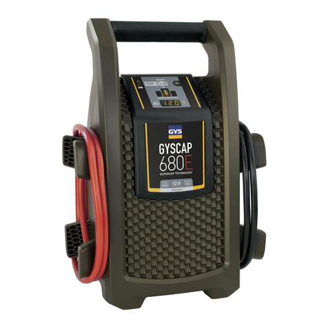
Theben RMG 8 User manual

Blinds and switch actuator RMG 8, blinds actuator JMG 4
and switch actuator module RME 8 - EIB theben
As of: Apr-06 (Subject to change without notice) Page 1 of 36
RMG 8 Switch Actuator
RME 8 / RMX 4 Switch Actuator Modules
JMG 4 Blinds Actuator
(for JMG 4 refer to Chapter 1.3)
JMG 4 490 0 250
RMG 8 490 0 251
RME 8 490 0 252
RMX 4 490 0 256
Key for JMG 4 / RMG 8 907 0 304

Blinds and switch actuator RMG 8, blinds actuator JMG 4
and switch actuator module RME 8 - EIB theben
As of: Apr-06 (Subject to change without notice) Page 2 of 36
Table of Contents
1Function Properties.......................................................................................................................... 3
1.1 Advantages .............................................................................................................................. 4
1.2 Areas of Application ............................................................................................................... 5
1.3 Differences between RMG 8 and JMG 4 ................................................................................ 5
2Technical Data................................................................................................................................. 6
2.1 General .................................................................................................................................... 6
2.2 Connection Data ...................................................................................................................... 7
2.3 Connection Diagram................................................................................................................ 8
3The "8x Switching / 4x Drive + Expansion" Application Program ................................................ 9
3.1 Function Properties.................................................................................................................. 9
3.2 Selecting in the Product Database ........................................................................................... 9
3.3 Communication Objects ........................................................................................................ 10
3.3.1 Introduction ................................................................................................................... 10
3.3.2 Overview ....................................................................................................................... 10
3.3.3 Description of the Objects ............................................................................................. 12
3.4 The Parameters ...................................................................................................................... 16
3.4.1 General .......................................................................................................................... 16
3.4.2 Drives General............................................................................................................... 17
3.4.3 Function of the Channels............................................................................................... 18
3.4.4 Drive x (Channel as Drive Controller) .......................................................................... 18
3.4.5 Channel X.Y (Parameterised for 2 Switching Outputs) ................................................ 20
4Commissioning.............................................................................................................................. 22
4.1 Reaction without ETS Programming..................................................................................... 22
4.2 ETS Programming without Mains Voltage ........................................................................... 22
4.3 Standard Drive Application................................................................................................... 22
4.4 Expert drive application ........................................................................................................ 24
4.4.1 Determining the Exact Full Running Time "Down" ..................................................... 24
4.4.2 Determining the Slippage Compensation of the Drive Mechanisms............................. 27
4.4.3 Feedback of the Drive Mechanism Height and Slat Positions ...................................... 29
5Operation....................................................................................................................................... 30
5.1 Operating Controls ................................................................................................................ 30
5.1.1 Buttons........................................................................................................................... 30
5.1.2 Light Emitting Diodes ................................................................................................... 30
5.2 Manual Mode ........................................................................................................................ 30
5.2.1 Manual Mode for Drive Channels................................................................................. 30
5.2.2 Manual Mode for Switching Channels.......................................................................... 30
5.3 Important Note ...................................................................................................................... 31
6Appendices .................................................................................................................................... 32
6.1 Priority Order of the Drive Controller................................................................................... 32
6.2 Priority Order of the Switching Output Controller................................................................ 33
6.3 Definition: Mains Voltage Recovery and Bus Voltage Failure............................................. 34
6.4 Troubleshooting..................................................................................................................... 35
6.5 Block Diagram of the Switching Output Controller.............................................................. 36

Blinds and switch actuator RMG 8, blinds actuator JMG 4
and switch actuator module RME 8 - EIB theben
As of: Apr-06 (Subject to change without notice) Page 3 of 36
1 Function Properties
The RMG 8 EIB blinds and switch actuator and the RME 8 / RMX 4 extension modules can be used
as a
•Drive controller for blinds, roller shutters and sunshades, and as a
•Switch actuator, e.g. for lighting, ventilation and the like.
If used as a lighting controller, the individual channels of the RMG 8 and RME 8 / RMX 4 devices can
be parameterised:
•As a switch actuator (on/off without delay)
•As a delay mechanism for on/off operations (delay times can be individually set)
•As a pulsing function (activation restricted by timeout)
•As an automatic time switch for staircase lighting with cut out early warning (after the preset
time has elapsed, the light is switched off temporarily (for 0.25 s) and then switched on again for
30s).
Several inhibit and control objects enable a remote control of the connected devices, e.g. central
raising or lowering of blinds/roller shutters/shading devices or central inhibiting of individual or all
switching channels.
Via three safety objects, sunshades or sight protection devices can be retracted/extended to a defined
position, for example in the case of a storm or rain.
The application software distinguishes between standard and expert users (refer to the chapter Expert
Application).

Blinds and switch actuator RMG 8, blinds actuator JMG 4
and switch actuator module RME 8 - EIB theben
As of: Apr-06 (Subject to change without notice) Page 4 of 36
1.1 Advantages
•Modular device concept with as many as 8 driving or 16 switching channels.
•On-site device operation, e.g. an installation test of the drive mechanisms / lighting for example is
also possible without bus voltage.
•LED status indicators of the outputs: Switching status, keyboard lock, higher priority
•Every driving channel can be parameterised to act as two switching channels (except for JMG 4).
•Every switching channel can be programmed to act as a convenient timer.
•The staircase lighting period can be extended by repeated actuation of the switch.
(when a person has to clean the staircase, etc.). Cut out early warning function in compliance with
DIN 18015-2.
•Simple input of the execution times in the ETS.
•Large scope of functions due to 47 objects.
•Even with traditional drive mechanisms any desired position can be approached due to the
slippage compensation.
•Forced object (all drives up or down with highest priority) e.g. for cleaning windows or in the case
of fire alarms.
•Flexible reaction to security telegrams: Can be set for each drive mechanism individually for the
beginning and end of the safety status.
•The behaviour in the case of a bus failure and in the case of a recovery of the bus/mains voltage
can be selected.
•Feedback of the position of the drive mechanism and the switching channel status for building
visualization.

Blinds and switch actuator RMG 8, blinds actuator JMG 4
and switch actuator module RME 8 - EIB theben
As of: Apr-06 (Subject to change without notice) Page 5 of 36
1.2 Areas of Application
The RMG 8 EIB switch actuator and the RME 8 / RMX 4 switch actuators module are suited for the
following applications (examples):
•Control of awnings, blinds, roller shutters as well as various sunshades and sight protection
devices
•Control of dormer windows and ventilation flaps
•Shading, lighting and heating greenhouses and winter gardens
•Lighting buildings and staircases
•Delayed activation/deactivation of groups of lights
•Short or long pulses for end-of-break gongs, toilet flushing installations or ventilation systems
1.3 Differences between RMG 8 and JMG 4
As opposed to RMG 8, JMG 4 is a pure drive controller and not a switch actuator.
The drive functions of the JMG 4 are completely identical to those of the RMG 8 but the switching
capacity of 8 A of the JMG 4 is lower (refer to the chapter Technical Data).
The two devices can be expanded with an RME 8 or RMX 4 module.
The extension modules can always be parameterised as desired as a drive controller or as a switch
actuator for light etc.

Blinds and switch actuator RMG 8, blinds actuator JMG 4
and switch actuator module RME 8 - EIB theben
As of: Apr-06 (Subject to change without notice) Page 6 of 36
2 Technical Data
2.1 General
Voltage supply: Via bus voltage and a separate A.C. power supply
Connections: 1 bus connection (RMG 8 and JMG 4 only)
1 power connection
4 channels (2 for the RMX 4) consisting of 2 relays each (n.o. contact)
Protection rating: IP 20 in compliance with DIN EN 60 529
Protection class: II following proper installation
Permissible ambient
temperature: – 5 °C to + 45 °C (-5T45)
Housing dimensions: 45 x 105 x 60 mm 45x53,5x60mm (RMX 4) v(H/W/D)
Weight: approx. 450 g

Blinds and switch actuator RMG 8, blinds actuator JMG 4
and switch actuator module RME 8 - EIB theben
As of: Apr-06 (Subject to change without notice) Page 7 of 36
2.2 Connection Data
JMG 4 RMG 8 RME 8 / RMX 4
Operating voltage 230 V / 240 V ± 10 %
Rated frequency 50 Hz
Own consumption max. 4 VA
EIB current consumption 8 mA -
Contact-making material AgSnO
Contact type Potential-free make-contact element
Switching capacity (250 V~):
cos φ= 1
cos φ= 0.6
8 A
5 A
10 A
6 A
Power consumption of the
incandescent lamp
1400 W
Power consumption of the
halogen lamp
1400 W
Conv.tubular fluorescent lamps:
uncompensated / compensated in
series
19 x 40 W, 13 x 58 W, 8 x 100 W
compensated in parallel
5 x 40 W (4.7 μF), 3 x 58 W (7.0 μF)
1 x 100 W (18 μF)
dual switch 6 x (2 x 58 W), 4 x (2 x 100 W)
Fluorescent flashlights with ECG 4 x 58 W
Tubular fluorescent lamps with
ECG – dual switch
2 x (2 x 58 W)
Mercury discharge lamps:
uncompensated
compensated in parallel
Use a contactor
Sodium discharge lamps:
uncompensated
compensated in parallel
Use a contactor
Compact fluorescent lamps with
ECG
32 x 5 W, 30 x 7 W, 13 x 8 W, 13 x 11 W,
17 x 15 W, 10 x 20 W, 10 x 23 W
Compact fluorescent lamps with
conventional control gear
-
1200 W

Blinds and switch actuator RMG 8, blinds actuator JMG 4
and switch actuator module RME 8 - EIB theben
As of: Apr-06 (Subject to change without notice) Page 8 of 36
2.3 Connection Diagram
Connecting the EIB Installation Bus

Blinds and switch actuator RMG 8, blinds actuator JMG 4
and switch actuator module RME 8 - EIB theben
As of: Apr-06 (Subject to change without notice) Page 9 of 36
3 The "8x Switching / 4x Drive + Expansion" Application Program
See chapter 1.3: Differences between RMG 8 and JMG 4
3.1 Function Properties
The application program provides the functions listed below.
Function Description
General Basic device settings: Device type, keyboard lock, manual mode
Drives general Monitoring of the security objects, neutral position of the slats
Function of the channels This function is used to define which channels are to be
parameterised as drive controller and which are to be parameterised
as switching channels
Drive 1 to 4 (to 8) Is displayed when the respective channel is parameterised as a drive
controller
Channel 1.1 / 1.2 ... 4.1 / 4.2
(... 8.1 / 8.2)
Is displayed when the respective channel is parameterised as a
switching channel
IMPORTANT: After downloading the application or after the bus voltage has been restored, it
may take up to 15 seconds until the device is ready again for operation.
3.2 Selecting in the Product Database
Manufacturer: THEBEN-WERK ZEITAUTOMATIK
Product family Output
Product type: Drives and switches; modular
Product name: RMG 8 / JMG 4 (see 1.3: Differences between RMG 8 and JMG 4)
Download the application from: http://www.theben.de

Blinds and switch actuator RMG 8, blinds actuator JMG 4
and switch actuator module RME 8 - EIB theben
As of: Apr-06 (Subject to change without notice) Page 10 of 36
3.3 Communication Objects
3.3.1 Introduction
The basic setting for each channel is the parameterization as a drive controller or as a switching
channel with 2 outputs.
The function and thus the type and designation of the individual objects depend on the use of the
corresponding channel, i.e. drive, roller shutter, blinds, switching channel, timer and the like.
In this case, we will use channel 1 as an example.
3.3.2 Overview
3.3.2.1 Channel Parameterised as a Drive Mechanism
When the channel is parameterised as a drive mechanism, you can select the type of element that is to be driven
(see the table below).
Selected type of driven elementObject
no. Property Roller shutter / textile sunshade Blinds
Name Drive 1 up/down
Function up / down
Type 1 Bit
0
Reaction receive
Name Drive 1 stop Drive 1 step / stop
Function Stop roller blind Step/stop shutter
Type 1 Bit
1
Reaction receive
Name Drive 1 height
Function Height [%]
Type 1 Byte
2
Reaction receive / (feedback height)
Name Drive 1 slats
Function Position of the slats in %
Type 1 Byte
3
Reaction
not available
receive / (feedback slats position)
Name Drive 1 auto comfort
Function Auto comfort
Type 1 Bit
4
Reaction receive

Blinds and switch actuator RMG 8, blinds actuator JMG 4
and switch actuator module RME 8 - EIB theben
As of: Apr-06 (Subject to change without notice) Page 11 of 36
Channel Parameterised as a Switching Channel with 2 Outputs
If the channel is parameterised as a switching channel with 2 outputs, one of four timing functions can be
selected for each channel (see the table below).
Selected timing functionObject
no. Property switch ON/OFF staircase time
switch with cut out
early warning
impulse function ON / OFF delay
Name Channel 1.1 switch Channel 1.1
staircase time
switch
Channel 1.1
impulse
Channel 1.1 switch
Function ON/OFF Start / stop Delayed ON/OFF
Type 1 Bit
0
Reaction receive
Name Channel 1.1 state
Function Feedback
Type 1 Bit
1
Reaction send
Name Channel 1.2 switch Channel 1.2
staircase time
switch
Channel 1.2
impulse
Channel 1.2 switch
Function ON/OFF Start / stop Delayed ON/OFF
Type 1 Bit
2
Reaction receive
Name Channel 1.2 state
Function Feedback
Type 1 Bit
3
Reaction send
Name Inhibit Channels 1.X
Function Inhibit Channels 1.1 and 1.2
Type 1 Bit
4
Reaction receive
Number of communication objects 47
Number of group addresses: 85
Number of associations: 85

Blinds and switch actuator RMG 8, blinds actuator JMG 4
and switch actuator module RME 8 - EIB theben
As of: Apr-06 (Subject to change without notice) Page 12 of 36
3.3.3 Description of the Objects
•Object 0
Name
(refer to the overview)
Function
Drive 1 up/down Raise roller shutter/blinds with "0" and lower them with "1"
Channel 1.1 switch Switch on the relay with "1" and switch it off with "0"
Channel 1.1 staircase
time switch
Activate automatic staircase time switch with "1" and deactivate it with "0".
As soon as the parameterised time has elapsed or when a "0" is sent to the
object, the relay switches off after a cutout early warning.
cutout early warning: The relay switches off for ¼ of a second, switches on
again for 30 seconds and then switches off completely.
Channel 1.1 impulse Activate the impulse with "1" and deactivate it with "0".
As soon as the parameterised pulse time has elapsed or when a "0" is sent to
the object, the relay switches off.
Channel 1.1 delayed
ON/OFF
If a "1" is sent to the object, the relay switches on after the parameterised
period of delay.
If a "0" is sent, the delay refers to the switch-off time.
Special cases:
A "0" sent during the switch-on delay period or a "1" sent during the switch-
off delay period interrupts the procedure.
•Object 1
Name
(refer to the overview)
Function
Drive 1 stop A "1" or a "0" sent to the object stops the raising or lowering operation.
Drive 1 step/stop If the blind is moving, it will be stopped.
Otherwise, a short movement of the slats is performed (step mode).
The direction of the "step" is defined by sending either a "0" or a "1" to the
object.
Steps will not be performed after the maximum possible slat turn position has
been reached ("Full Slats turn" parameter).
Channel 1.1 state Feedback of the current relay status, e.g. for building visualization.
Example: A delayed switch-on operation is started, the feedback object is set
when the relay is switched on following the elapsed delay period.

Blinds and switch actuator RMG 8, blinds actuator JMG 4
and switch actuator module RME 8 - EIB theben
As of: Apr-06 (Subject to change without notice) Page 13 of 36
•Object 2
Name
(refer to the overview)
Function
Drive 1 height Raise/lower the roller shutter/blinds to a specific position.
The position value is specified in %.
0% ... 3% = upper end of travel
100 % = lower end of travel
Can be inhibited by the Auto comfort object (see below).
If the target position is too near (i.e. within the turning time of the slats), the
command is suppressed.
If desired, this object can send the position of the driven element to the bus
(refer to the chapter Professional Drive Application).
Channel 1.2
switch,
staircase time switch,
impulse
Same functions as object 0 for channel 1.1
•Object 3
Name
(refer to the overview)
Function
Drive 1 slats Presetting of a specific slat turn value in %.
Can be inhibited by the Auto comfort object (see below).
Channel 1.2 state Same function as object 1 for channel 1.1
•Object 4
Name
(refer to the overview)
Function
Drive 1 auto comfort Sending a "1" to this object inhibits the functions Drive 1 height and Drive 1
slats.
This function is used to prevent the manipulation of the blind position by
third-party interference and thus to maintain a preferred position of the slats.
The up/down functions (objects 0 and 1) remain operational.
Inhibit channels 1.X Sending a "1" to this object inhibits channel 1.1 and channel 1.2
(see table 1-5, Parameter „Dependence on object Inhibit channels 1.X“)
Annotation:
The reaction of the objects 5 to 39 is identical to that of the objects 0 to 4 and they represent either the
drives 2 to 8 or the channels 2.1 to 8.2.

Blinds and switch actuator RMG 8, blinds actuator JMG 4
and switch actuator module RME 8 - EIB theben
As of: Apr-06 (Subject to change without notice) Page 14 of 36
•Objects 40, 41, 42
Name
(refer to the overview)
Function
Central priority 1, 2
and 3
Security objects:
A security object enables an aimed reaction of the drives to a specific
situation with a high priority (refer to the appendix Priority Order of the
Drive Controller).
Example:
A safety object is connected to a wind sensor.
A drive connected to a textile sunshade is parameterised to react to this
security object.
For as long as a "0" is being sent, the standard operating status is assumed.
In the case of a storm, the wind sensor sends a "1" to the security object and
the sunshade is immediately retracted to the parameterised safety position.
IMPORTANT: A security object may be controlled by one device only. Otherwise different
commands may cancel each other.
Annotation: Reading the security objects i.e. with “read value” function of ETS software:
If the security status was initiated by cyclical monitoring, the value of this
object will remain 0
•Object 43
Name
(refer to the overview)
Function
Drives central Using this object, all the drive mechanisms parameterised accordingly can be
controlled from one central point.
With this function, all the roller shutters of a building front, for example, can
be raised or lowered simultaneously by pressing one button.
0 = raise
1 = lower

Blinds and switch actuator RMG 8, blinds actuator JMG 4
and switch actuator module RME 8 - EIB theben
As of: Apr-06 (Subject to change without notice) Page 15 of 36
•Object 44
Name
(refer to the overview)
Function
Drives central priority
Forced up/down (2-bit object)
The function corresponds to that of the Drives central object (see above) but
this object has the highest priority and overrides all the other objects for as
long as it is set.
Areas of application: e.g. when cleaning the windows, in the case of fire
fighting actions etc.
Recommendation: If used, always send cyclically.
Refer to the appendix Priority Order of the Drive Controller.
Data format:
- - - - - - X Y
1 = forced obj. active
0 = forced ob
j
. inactive
1 = up
0
=
down
•Object 45
Name
(refer to the overview)
Function
Central permanent ON For controlling switching outputs.
Using this object, all the switching channels parameterised accordingly can
be controlled from one central point.
In this case, for example, all the lights on one floor with the highest priority
can be switched on simultaneously by pressing one button (refer to the
appendix Priority Order – Switching Output Controller).
•Object 46
Name
(refer to the overview)
Function
Central permanent
OFF
For controlling switching outputs.
Using this object, all the switching channels parameterised accordingly can
be controlled from one central point.
In this case, for example, all the lights on one floor with the highest priority
can be switched off simultaneously by pressing one button (refer to the
appendix Priority Order – Switching Output Controller).

Blinds and switch actuator RMG 8, blinds actuator JMG 4
and switch actuator module RME 8 - EIB theben
As of: Apr-06 (Subject to change without notice) Page 16 of 36
3.4 The Parameters
3.4.1 General
The "General" tab is used for setting the basic parameters.
The parameters that can be set are listed in the table below.
Table 1-1: Parameters on the "General" tab
Designation Values Description
Used device(s) only RMG 8
RMG 8 and RME 8
RMG 8 and RMX 4
Select whether only the basic
device (4 drives) or the basic device
+ an extension (a total of 8 or 6
drives) is/are available
Device keys are always enabled
only enabled if theben-key for JMG
4 / RMG 8 (item no. 907 0 304) is
plugged
Key lock deactivated
If the option "only enabled if key is
plugged" is selected, the device
keyboard is locked and manual
operation is possible only if a key is
inserted in the interface on the front
of the device.
Manual mode
automatically cleared after 30 min
permanent !
Function of the "manual" button on
the device.
The time limit of 30 minutes
prevents a permanent disturbance of
the system if the "manual" button
was pressed e.g. by unauthorized
persons.
If a time limit is not selected, the
manual mode is exited only if the
following events occur:
•the button is pressed once more
•the bus voltage is restored
•the mains voltage is interrupted
•the device is reprogrammed

Blinds and switch actuator RMG 8, blinds actuator JMG 4
and switch actuator module RME 8 - EIB theben
As of: Apr-06 (Subject to change without notice) Page 17 of 36
3.4.2 Drives General
Table 1-2: Parameters on the "Drives general" tab
Designation Values Description
Security 1 – 3 (objects) without cyclical monitoring
with cyclical monitoring
The last telegram always
determines the security status.
If a security object has been
assigned an important alarming
function, a check is performed
whether the alarm sensor sends data
periodically.
If the sender fails, the security
status is taken up.
Example (see below).
Cyclical monitoring of
all 3 Objects 1 ... 255
[x 1min]
Input: 1 to 255 If the sensors connected to the
security objects send cyclically, the
cycle time, i.e. the time interval
between 2 telegrams must be
entered here.
Recommendation: The monitoring
time of the actuator must be twice
as long as the cycle time of the
device to be monitored.
Example:
If the air speed meter sends to the
security object 1 every 5 minutes,
set the monitoring time to 10
minutes.
Allocation of the 0%
Position to the objects
Slats [%]
0% corresponds to travel down
position
0% corresponds to travel up position
Input of the reference position for
calculating the slats turn.
User level for drives Standard
Expert
Only standard parameters for
standard use.
On the expert level, the blinds
actuator can be precisely adjusted
in relation to the drives. Thus,
utmost positioning accuracy can be
attained.
Standard parameters for the "expert" user level
(Descriptions: refer to the chapter Expert Application).

Blinds and switch actuator RMG 8, blinds actuator JMG 4
and switch actuator module RME 8 - EIB theben
As of: Apr-06 (Subject to change without notice) Page 18 of 36
3.4.3 Function of the Channels
Table 1-3: Parameters on the "Function of the channels" tab
Designation Values Description
Function of channel 1,
2, 3, 4 ... 8
Drive
2 switching outputs
Each channel can either be
parameterised as a drive controller
or as a controller for 2 switching
outputs.
IMPORTANT: When changing the function of channels from switching channel to drive (or vice
versa), the device must be reset by interrupting the power supply (for at least 2 s).
3.4.4 Drive x (Channel as Drive Controller)
Table 1-4: Parameters on the "Drive 1, Drive 2 ... Drive 8" tab
Designation Values Description
Drive application Shutter / awning
Blind
The type of device that is to be
driven.
Full running time
"down"
50 ... 10.000 [x 0.1s]
Keyboard input 50 to 10,000
Enter the measured runtime in 10th
of a second.
10 = 1 s, 100 = 10 s etc.
Full Slats turn*
20 ... 200 [x 20 ms]
Keyboard input 20 to 200 Enter the measured turning time of
the slats in steps of 20 ms.
100 = 100 x 20 ms = 2 s
Step time for object
"step/stop shutter*
3 ... 55 [x 20 ms]
Keyboard input 3 to 55 Desired pulse length for step/stop
mode.
10 = 10 x 20 ms = 0.2 s
Position at security
begin / end
no reaction
upper end of travel / unchanged
upper end of travel / lower end of
travel
lower end of travel / unchanged
lower end of travel / upper end of
travel
Reaction of the driven element
when the "Security" status is
enabled and disabled.
In the case of the standard
application "upper end of travel /
unchanged" the drive moves the
driven element to the upper end of
travel as soon as the security status
is enabled (e.g. due to a storm) and
remains in this position when the
security status is disabled.

Blinds and switch actuator RMG 8, blinds actuator JMG 4
and switch actuator module RME 8 - EIB theben
As of: Apr-06 (Subject to change without notice) Page 19 of 36
Table 1-4: continued
Designation Values Description
Which security objects
have to act (logical
"OR" combination)
security 1
security 2
security 3
security 1 and 2
security 1 and 3
security 2 and 3
security 1, 2 and 3
Setting that defines to which
security object the drive is to
respond.
If several are selected, such as
1 and 3, these are linked by a
logical OR operation.
Example:
Security 1 and 3 are to cause a
reaction.
As soon as one of the two security
objects is addressed, the status
„Security“ is active and the drive
moves the driven element to the
parameterised security position.
Dependence on object
"Drives central
up/down"
no
yes
Is this drive to react to the "Drives
central up/down" object?
Behaviour after BUS
voltage loss
upper end of travel
lower end of travel
unchanged
After a bus failure (with existing
power supply), the drive move the
driven element to a preferred
position (e.g. open the roller
shutter)
Behaviour after BUS
voltage recovery**
upper end of travel
lower end of travel
unchanged
Refer to the row above
Behaviour at mains
voltage recovery
without BUS voltage
upper end of travel
lower end of travel
unchanged
Even after a recovery of the mains
voltage, the drive can move the
driven element to a "starting
position".
* For blinds ONLY
** In typical applications, the reaction after a recovery of the bus voltage is set identical to the reaction after a
recovery of the mains voltage without bus voltage.

Blinds and switch actuator RMG 8, blinds actuator JMG 4
and switch actuator module RME 8 - EIB theben
As of: Apr-06 (Subject to change without notice) Page 20 of 36
3.4.5 Channel X.Y (Parameterised for 2 Switching Outputs)
Table 1-5: Parameters on the "Channel X.Y" tabs
Designation Values Description
Timer functions switch ON/OFF
staircase time switch with cut out
early warning
impulse function
ON / OFF delay
Selection of a timer function from 4
options for each of the switching
outputs.
Dependence on object
"Central permanent
ON"
no
yes
Is the Central permanent ON object
to switch this channel as well?
Dependence on object
"Central permanent
OFF"
no
yes
Is the Central permanent OFF
object to switch this channel as
well?
Dependence on object
"Inhibit channels 1.X"
no
yes
Is the inhibit object to have
influence over this channel?
Behaviour after BUS
voltage loss
unchanged
switch ON
switch OFF
Serves for taking on a defined
status after a bus failure,
This is important for consumers,
e.g. that must not continue
operation without control.
Behaviour after BUS
recovery*
unchanged
switch ON
switch OFF
trigger timer**
Similar to the previous row.
Important for consumers, e.g. that
must not start operating again
without control.
Behaviour at mains
voltage recovery
without BUS voltage
switch ON
remain OFF
restore previous relay state
Refer to the rows above
Parameters for the staircase time switch
Time base for staircase
timer
1 sec, 10 sec, 30 sec, 1 min To attain a maximum of flexibility,
the staircase lighting time is
calculated from a time base and a
factor
Factor for staircase
timer
1 ... 255 x Time base
Keyboard input 1 to 255 The staircase lighting time is equal
to the time base multiplied by the
factor.
Example:
Time base 10 s x factor 2 is
2 x 10 s = 20 s
As soon as this time has elapsed, a
cutout early warning is issued, i.e.
the light is switched off for 0.25 s
and then switched on again for 30s.
After this, the feedback is sent (obj.
1). (The cutout early warning
intervals (0.25 s and 30s) are
preprogrammed and cannot be
changed).
This manual suits for next models
8
Table of contents
Other Theben Controllers manuals
Theben
Theben HMG 8 User manual
Theben
Theben MIX 2 Series User manual
Theben
Theben TC 649 E User manual
Theben
Theben FCA 2 User manual
Theben
Theben PH-II Series User manual
Theben
Theben Mix Series User manual
Theben
Theben RM 4 H FIX1 User manual
Theben
Theben RAMSES 856 top2 Installation guide
Theben
Theben DU 1 User manual
Theben
Theben JMG 4 T KNX User manual
Popular Controllers manuals by other brands
ready robotics
ready robotics Forge/OS 5 Startup guide

Critical Environment Technologies
Critical Environment Technologies FCS-M Series Operation manual
Fluidwell
Fluidwell D Series manual

Mitsubishi Electric
Mitsubishi Electric AE-200A Instruction book
Festo
Festo SPC200 Series manual
SOMFY
SOMFY ROLLIXO user manual
