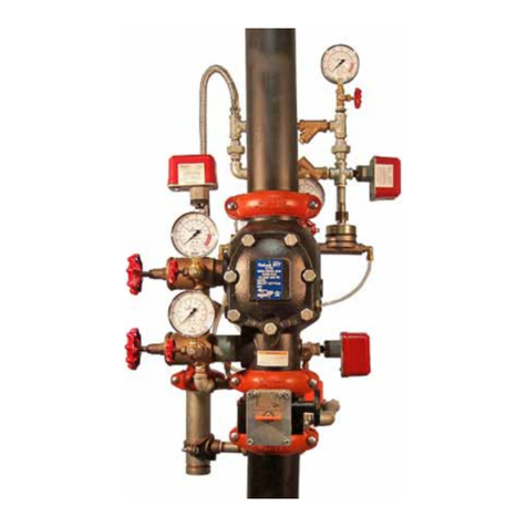
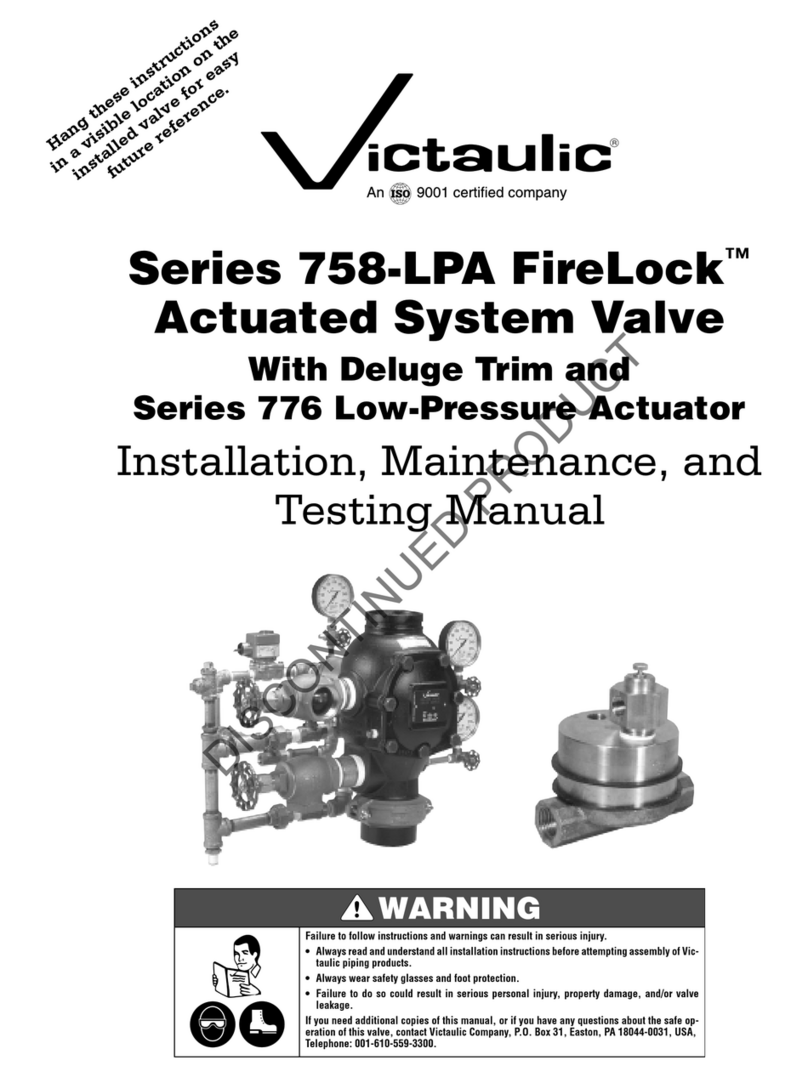
Victaulic FireLock 758-EPA Series User manual

Series 758-EPA
FireLock
™
Preaction Valve
with Series 79N
Electric/Pneumatic Actuator
Double-Interlock Electric/Pneumatic Release
Hang these instructions on the
installed valve for easy future reference.
Failure to follow instructions and warnings can result in serious personal injury, property damage, and/or product failure.
• Read and understand all installation instructions before attempting to install any Victaulic piping products.
•Wear safety glasses, hardhat, and foot protection.
If you need additional copies of any literature, or if you have any questions about the safe installation and operation of this product,
contact Victaulic Company, P.O. Box 31, Easton, PA 18044-0031, USA, Telephone: 1-800-PICK VIC, e-mail: [email protected].
Installation, Maintenance, & Testing Manual
R
DISCONTINUED PRODUCT

1
TABLE OF CONTENTS
HAZARD IDENTIFICATION
Definitions for identifying the various hazard levels are provided below.
This safety alert symbol indicates important safety messages. When you see this symbol, be alert to the
possibility of personal injury. Carefully read and fully understand the message that follows.
NOTICE
The use of the word “NOTICE” identifies special instructions that are
important but not related to hazards.
The use of the word “CAUTION” identifies possible hazards or unsafe prac-
tices that could result in personal injury and product or property damage if
instructions, including recommended precautions, are not followed.
The use of the word “WARNING” identifies the presence of hazards or un-
safe practices that could result in death or serious personal injury if in-
structions, including recommended precautions, are not followed.
® Registered Trademark ofVictaulic © Copyright 2002 Victaulic Printed in U.S.A.
Hazard Identification . . . . . . . . . . . . . . . . . . . . . . . . . . . . . .1
Installer Safety Instructions . . . . . . . . . . . . . . . . . . . . . . . . .2
Introduction. . . . . . . . . . . . . . . . . . . . . . . . . . . . . . . . . . . . . .3
Trim Dimensions. . . . . . . . . . . . . . . . . . . . . . . . . . . . . . . . . .3
Exploded View Drawing - Trim Components. . . . . . . . . . .4
Exploded View Drawing - Internal Valve Components. . .5
Series 758 Preaction Valve with Series 79N Electric/
Pneumatic Actuator – Trim Assembly
Drawing Numbers . . . . . . . . . . . . . . . . . . . . . . . . . . . . . . .5
Section View Drawing and Description – 79N Electric/
Pneumatic Actuator. . . . . . . . . . . . . . . . . . . . . . . . . . . . . .6
Section View Drawing and Description – Series 746
Dry Accelerator. . . . . . . . . . . . . . . . . . . . . . . . . . . . . . . . . .7
Compressor and Air Maintenance Trim Requirements . .8
Air Supply Design. . . . . . . . . . . . . . . . . . . . . . . . . . . . . . .8
Proper Air Supplies for Series 758 Preaction
Valves Used with Series 79N Electric/Pneumatic
Actuators. . . . . . . . . . . . . . . . . . . . . . . . . . . . . . . . . . . . . .9
Proper Air Supplies for Series 758 Preaction
Valves Used with Series 79N Electric/Pneumatic
Actuators and Series 746 Dry Accelerators . . . . . . . . . .9
Important Installation Information. . . . . . . . . . . . . . . . . . . .9
Valve/Trim Installation . . . . . . . . . . . . . . . . . . . . . . . . . . . .10
Important Settings . . . . . . . . . . . . . . . . . . . . . . . . . . . . . . .10
Hydrostatic Testing . . . . . . . . . . . . . . . . . . . . . . . . . . . . . .10
Placing the System in Service. . . . . . . . . . . . . . . . . . . . . .11
External Inspection . . . . . . . . . . . . . . . . . . . . . . . . . . . . . . 17
Weekly Inspection. . . . . . . . . . . . . . . . . . . . . . . . . . . . . 17
Monthly Inspection. . . . . . . . . . . . . . . . . . . . . . . . . . . . 17
Required Tests . . . . . . . . . . . . . . . . . . . . . . . . . . . . . . . . . . 17
Main Drain Test. . . . . . . . . . . . . . . . . . . . . . . . . . . . . . . 17
Water Flow Alarm Test . . . . . . . . . . . . . . . . . . . . . . . . . 18
Water Level and Low-Air Alarm Tests . . . . . . . . . . . . 20
Trip Tests . . . . . . . . . . . . . . . . . . . . . . . . . . . . . . . . . . . . . . 23
Partial Trip Test . . . . . . . . . . . . . . . . . . . . . . . . . . . . . . . 23
Full Trip Test . . . . . . . . . . . . . . . . . . . . . . . . . . . . . . . . . 24
Required Internal Inspection . . . . . . . . . . . . . . . . . . . . . . 26
Maintenance . . . . . . . . . . . . . . . . . . . . . . . . . . . . . . . . . . . 28
Removing and Replacing Clapper Seal. . . . . . . . . . . . 28
Removing and Replacing Clapper Assembly . . . . . . . 30
Installing Cover Plate Gasket and Cover Plate . . . . . . 31
Removing and Replacing Piston Assembly . . . . . . . . 32
Replacing the Strainer Screen for Series 79N
Electric/Pneumatic Actuators . . . . . . . . . . . . . . . . . . . 33
Troubleshooting – Series 79N Electric/Pneumatic
Actuator . . . . . . . . . . . . . . . . . . . . . . . . . . . . . . . . . . . . . 34
Troubleshooting – Series 746 Dry Accelerator . . . . . . . . 34
Troubleshooting – System . . . . . . . . . . . . . . . . . . . . . . . . 34
Warranty. . . . . . . . . . . . . . . . . . . . . . . . . . . . . . . . . . . . . . B/C
Facilities Locations . . . . . . . . . . . . . . . . . . . . . . . . . . . . .B/C
DISCONTINUED PRODUCT

2
INSTALLER SAFETY INSTRUCTIONS
GENERAL
1.
Read and understand all instructions before proceeding with the installation, maintenance, and testing of this
Victaulic fire protection device.
2.
Use only recommended accessories.
Use of improper accessories or equipment could result in improper system operation.
3.
Avoid dangerous environments.
If using electrically powered tools for installation, make sure the area is moisture-free. Keep
work areas well lit. Allow enough space for installing the device, trim, and accessories safely and efficiently.
4.
Prevent back injury.
Larger and pre-trimmed valves are heavier and may require more than one person or mechanical lifting
equipment to position and install the assembly properly. Always practice proper lifting techniques.
5.
Inspect the shipment.
Make sure all components are included with the shipment and that all necessary tools are available for
proper installation.
6.
Wear safety glasses, hardhat, foot protection, and hearing protection.
Protect your hearing if you are exposed to long
periods of very noisy job-site operations.
7.
Watch for pinch points.
Do not put fingers under the valve body where they could be pinched by the weight of the valve. Use
caution around spring-loaded components, such as the clapper, the clapper latch, and the piston assembly.
8.
Keep work areas clean.
Cluttered areas, benches, and slippery floors can create hazardous working conditions.
9.
Keep visitors away.
Keep all visitors a safe distance away from work areas.
MAINTENANCE AND TESTING
1.
Notify the authority having jurisdiction.
Always notify the authority having jurisdiction before taking a fire protection
system out of service, or before performing any maintenance that eliminates the fire protection provided by the system.
2.
Depressurize and drain the system completely before performing any maintenance.
Water under pressure, trapped
air, or system air pressure may be present and can create hazardous conditions.
3.
Follow NFPA requirements for testing and inspection schedules.
Contact the local authority having jurisdiction for any
additional requirements.
4.
Keep the preaction system away from corrosive atmospheres and foreign matter.
Any condition that might degrade
the system or affect system performance must be avoided.
•Anexperienced,trainedinstallermustinstallthisproductinaccordancewithallinstructions.Theseinstructions
contain important information.
Failure to follow these instructions could result in serious personal injury, property damage, and/or product
failure.
Ifyouneedadditionalcopiesof any literature,orif you haveanyquestions about thesafeinstallation and operation
of this valve, contact Victaulic Company, P.O. Box 31, Easton, PA 18044-0031 USA, Telephone: 1-800-PICK Vic,
e-mail: [email protected].
• Depressurize and drain piping systems before attempting to install or remove any Victaulic piping products.
Failure to follow this instruction could result in serious personal injury, property damage, and/or product
damage.
DISCONTINUED PRODUCT

3
INTRODUCTION
The following instructions are a guide for proper installation of Victaulic Series 758 Preaction Valves. These instructions
involve pipe that is properly prepared and grooved in accordance with current Victaulic specifications.
TRIM DIMENSIONS
NOTE:
The drawings below show a 4-inch (100-mm) configuration.
VALVE SIZE Dimensions
inches/mm
Aprx. Weight Each
lbs./kg
Nominal
Outside
Dia.
in./
(mm)
Actual
Outside
Dia.
in./
(mm)
Without Trim With Trim
ABCDEFGH IFlanged Grooved Flanged Grooved
GROOVED
✕
GROOVED
1
¹⁄₂
1.900 9.00 32.00 13.00 18.00 13.00 10.00 7.00 4.00 4.00 – 16.7 – 43.0
40 48,3 228,60 813 330 457 330 254 178 102 102 – 7,6 – 19,5
2 2.375 9.00 32.00 13.00 18.00 13.00 10.00 7.00 4.00 4.00 – 17.0 – 43.0
50 60,3 228,60 813 330 457 330 254 178 102 102 – 7,7 – 19,5
2
¹⁄₂
2.875 12.61 33.00 14.00 20.00 15.50 11.50 7.50 5.00 5.00 – 41.2 – 65.0
65 73,0 320,29 838 356 508 393 292 191 127 127 – 18,7 – 29,5
76,1 mm 3.000 12.61 33.00 14.00 20.00 15.50 11.50 7.50 5.00 5.00 – 41.2 – 65.0
76,1 320,29 838 356 508 394 292 191 127 127 – 18,7 – 29,5
3 3.500 12.61 33.00 14.00 20.00 15.50 11.50 7.50 5.00 5.00 – 42.1 – 65.0
80 88,9 320,29 838 356 508 394 292 191 127 127 – 19,1 – 29,5
4 4.500 15.03 31.00 15.00 21.00 15.00 12.00 8.00 9.00 6.00 – 55.0 – 95.0
100 114,3 381,76 787 381 533 381 305 203 229 152 – 24,9 – 43,1
6 6.625 16.00 30.00 16.00 22.00 14.00 12.00 8.50 7.00 7.00 – 73.0 – 115.0
150 168,3 406,40 762 406 559 356 305 216 178 178 – 33,1 – 52,2
165,1 mm 6.500 16.00 30.00 16.00 22.00 14.00 12.00 8.50 7.00 7.00 – 73.0 – 115.0
165,1 406,40 762 406 559 356 305 216 178 178 – 33,1 – 52,2
8 8.625 17.50 30.00 16.00 23.00 16.00 12.00 14.00 9.50 7.00 – 142.0 – 182.0
200 219,1 444,50 762 406 584 406 305 356 241 178 – 64,4 – 82,6
GROOVED
✕
FLANGED
4 4.500 15.64 31.00 15.00 21.00 14.00 12.00 8.00 9.00 6.00 65.0 – 105.0 –
100 114,3 397,26 787 356 533 356 305 203 229 152 29,5 – 47,6 –
6 6.625 16.94 30.00 16.00 22.00 14.00 12.00 8.50 7.00 7.00 83.0 – 125.0 –
150 168,3 430,28 762 406 559 356 305 216 178 178 37,6 – 56,7 –
165,1 mm 6.500 16.94 30.00 16.00 22.00 14.00 12.00 8.50 7.00 7.00 83.0 – 125.0 –
165,1 430,28 762 406 559 356 305 216 178 178 37,6 – 56,7 –
8 8.625 19.27 30.00 16.00 23.00 16.00 12.00 14.00 9.50 7.00 155.0 – 195.0 –
200 219,1 489,46 762 406 584 406 305 356 241 178 70,3 – 88,5 –
D
B
A
H
E F C
G
I
NOTE: An optional Series 746 Dry Accel-
eratorassemblyaddsapproximately13.5"
(342,9 mm) onto the top of the Series
79N Electric/Pneumatic Actuator.
DISCONTINUED PRODUCT

4
EXPLODED VIEW DRAWING – TRIM COMPONENTS
Series 758 Actuated Valve With Double-Interlock, Pneumatic/Electric Release - Preaction Trim
(Optional Accessories Also Shown)
WATER MOTOR
ALARM
SERIES 760
UL
C
FM
LISTED
Water
Supply
29
27
Optional Air
Maintenance
Device
26 To
Drain
To
Drain
To
Drain
To
Drip Cup
To Upper
Alarm Outlet
To Lower
Alarm
Test Port
To
Drip Cup
To
Drain
To
Drip Cup
To
Drain
To
Atmosphere
To
Drip Cup
BILL OF MATERIALS
1 Series 758 FireLock Actuated CheckValve 20 System Pressure Gauge (0-80 psi/0-552 kPa with retard)
2 Piston Charge Line Ball Valve (NO) 21 Airline Strainer (100 Mesh)
3 Piston Charge Line Strainer (100 Mesh) 22 Airline Restrictor (¹⁄₁₆")*
4 Piston Charge Line Swing Check Valve 23 Series 79N Electric/Pneumatic Actuator
5 Piston Charge Line Restrictor (.070) 24 AutoVent*
6 Piston Charge Line Pressure Gauge (0-300 psi/0-2068 kPa) 25 Series 755 Manual Pull Station
7 Gauge Valve 26 Series 757 Air Maintenance Device (Optional)
8 Alarm Line Ball Valve (NO) 27 EPS-10 Alarm Pressure Switch (Optional)
9 Series 729 Drip Check Valve 28 EPS-40 Supervisory Switch (Optional)
10 Alarm Test Ball Valve (NC) 29 Series 760 Water Motor Alarm (Optional)
11 Alarm Line Drain Restrictor (¹⁄₁₆") 30 Series 705W Butterfly Valve (Optional)
12 Alarm Line Drain Ball Valve (NC) 31 Style 005 FireLock Rigid Coupling (Optional)
13 System Main Drain Valve 32 Upper Chamber Inlet Restrictor (¹⁄₃₂")*
14 Water Supply Main Drain Valve 33 Upper Chamber Strainer (100 Mesh)
15 Drip Cup 34 Upper Chamber CheckValve (¹⁄₄")
16 Drain Swing CheckValve 35 Series 75D Water Column Kit
17 Water Supply Pressure Gauge (0-300 psi/0-2068 kPa) 36 Strainer (100 Mesh)
18 Series 749 AutoDrain 37 Series 79N Upper Chamber Pressure Gauge
19 Series 748 Ball Check Valve 38 Series 79N Solenoid Coil
10
12
31
30
15
1
14
8
16
19
9
24
13
11
21
20
23 32
23
4
5
7
25
28
6
37
38
17
18
34
22 33
7
7
NO = Normally Open; NC = Normally Closed
* Part of the Series 79N Assembly
Flanged ✕Grooved
Series 75D
Water Column Kit
(Optional)
36
35
TO
DRIP
CUP
DISCONTINUED PRODUCT

5
EXPLODED VIEW DRAWING – INTERNAL VALVE COMPONENTS
SERIES 758 PREACTION VALVE WITH SERIES 79N ELECTRIC/
PNEUMATIC ACTUATOR – TRIM ASSEMBLY DRAWING NUMBERS
Valve Size
nominal inches
(mm)
Vertical Trim
Drawing
Number
Horizontal Trim
Drawing
Number
Valve Size
nominal inches
(actual mm)
Vertical Trim
Drawing
Number
Horizontal Trim
Drawing
Number
1
¹⁄₂
Z014758830 Z014758880 4Z040758830 Z040758880
40 100
2Z014758830 Z014758880 6Z060758830 Z060758880
50 150
2
¹⁄₂
Z024758830 Z024758880 165,1 mm Z060758830 Z060758880
65
76,1 mm Z024758830 Z024758880 8Z080758830 Z080758880
200
3Z024758830 Z024758880
80
1
17
16
12
11
21
20
9
4
19
3
10
18
7
6
5
814
13
2
15
BILL OF MATERIALS
1 Valve Body 8 Bolt Seal 15 Cover Plate Bolts (Qty.7)
2 Clapper 9 Clapper Spring 16 Piston
3 Clapper Seal 10 Spacers (Qty. 2) 17 Piston O-ring
4 Seal Ring 11 Clapper Shaft 18 Latch
5 Seal Washer 12 Clapper Shaft Retaining Plug (Qty. 2) 19 Latch Spring
6 Seal Retaining Ring 13 Cover Plate 20 Latch Shaft
7 Seal Assembly Bolt 14 Cover Plate Gasket 21 Latch Shaft Retaining Plug (Qty. 2)
Clapper
Latch
Piston
Assembly
Alarm
Outlet
Alarm
Test Seat
Seal
"WEEP" Hole
(Deluge and Preaction Valves)
Exaggerated for Clarity
NOTE: Valve is in the set position.
DISCONTINUED PRODUCT

6
SECTION VIEW DRAWING AND DESCRIPTION –
SERIES 79N ELECTRIC/PNEUMATIC ACTUATOR
The Series 79N Electric/Pneumatic Actuator is a single-
unit device used in the actuation of Series 758 Preaction
Valves with double-interlock electric/pneumatic trim.
Diaphragms separate the Series 79N into four chambers.
The upper and upper-middle chambers control the
actuation, while the lower and lower-middle chambers
act as the water control valve.
During system charging, air pressure enters the upper-
middle chamber of the Series 79N. Pulling up on the auto
vent, which is located on the Series 79N trim, sets the air
pressure in this upper-middle chamber. Water supply
pressure from the piston charge line enters the upper
chamber, and the normally closed solenoid, which is built
into the Series 79N, sets this water pressure.
There is no
need to activate the solenoid in order to set the
system.
The system air pressure in the upper-middle chamber
exerts a closing force on the middle chamber of the Series
79N. Additionally, the water supply pressure from the
piston charge line exerts a closing force on the middle
diaphragm through a piston that connects the upper and
middle diaphragms. These pressures close the water path
of the lower-middle chamber.
When the piston charge line is open, water enters the
lower chamber of the Series 79N; this water flows to the
lower-middle chamber through the inlet. The middle
diaphragm traps water in the lower-middle chamber.
Supply water pressure in the upper chamber and system
air pressure in the upper-middle chamber hold the lower-
middle diaphragm assembly closed.
Since the area of the lower diaphragm is greater than the
area of the lower chamber, the lower chamber seals;
therefore, no water flows to the actuator’s outlet, and the
water pressure creates a seal.
When system air pressure decays to 6.5 psi (45 kPa), the
auto vent’s compression spring exerts a force greater than
the air pressure in the upper-middle chamber. The auto
vent opens, and all air pressure in the upper-middle
chamber evacuates. During this condition, the Series 79N
will not actuate, since the water pressure in the upper
chamber maintains a closing force on the water seal of
the lower-middle chamber.
Likewise, if there is an electrical detection event, the
solenoid on the upper chamber will activate and cause
the upper chamber’s water pressure to release. The Series
79N will not actuate, since the upper-middle chamber’s
air pressure exerts a closing force on the lower-middle
chamber’s water seal.
The Series 79N will actuate only when an electrical
detection and loss of system air pressure occur. During
this condition, the closing force on the lower-middle
diaphragm’s water seal is removed, and the lower-middle
chamber’s water pressure releases. This allows the lower
diaphragm to lift and water to flow from the Series 79N’s
inlet to the outlet. This water flow releases water pressure
from the preaction valve’s piston and allows the piston to
retract. The preaction valve’s clapper opens, and water
flows into the sprinkler system.
WATER IN
WATER IN
Located in the
trim of the
upper-middle chamber
TO DRAIN
TO DRAIN
116
26
14
12
13
11
3
25
21
19
18
17
20
4
24
23 22
15
5
78910
6
2
1Upper Chamber
2 Upper Diaphragm
3 Upper-Middle Chamber
4 Middle Diaphragm
5 Lower-Middle Chamber
6 Lower Diaphragm
7 Strainer Assembly
8 Strainer o-ring
9 Strainer Screen
10 Lower Chamber
11 Solenoid Valve
12 Auto Vent
13 Auto Vent Protective Cap
14 Auto Vent Knob
15 Outlet Orifice
16 Gasket
17 Upper Piston
18 Isolating Diaphragm
19 Lower Pison
20 Middle Spring
21 Lower Spring
22 Outlet Eyelet
23 Inlet Eyelet
24 Isolating Diaphragm Retainer
25 Upper Diaphragm Retainer
26 Outlet Orifice O-ring
BILL OF MATERIALS
Exaggerated for clarity
Item Description
DISCONTINUED PRODUCT

7
SECTION VIEW DRAWING AND DESCRIPTION –
SERIES 746 DRY ACCELERATOR
The Series 746 Dry Accelerator exhausts air from the actuator to speed the operation of the valve.
A diaphragm separates the Series 746 Dry Accelerator into two chambers. The closing chamber contains a compression
spring, which maintains this chamber in the closed position. This closed position is maintained as long as the pressure
differential between the opening and closing chambers is less than 3 psi (21 kPa).
When the system introduces air pressure into the dry accelerator, the air goes into the closing chamber and passes
through a built-in check valve to the opening chamber. The built-in check valve, which allows flow into the opening
chamber, prevents pressure from escaping the opening chamber. Therefore, air can escape only through the restrictor.
When a rapid loss of system air pressure occurs, such as an open sprinkler, air escapes from the closing chamber faster
than it does from the opening chamber. As the sprinkler system’s pressure continues to decay, a differential pressure
develops across the diaphragm. When this differential pressure reaches 3 – 5 psi (21 – 34 kPa), the opening chamber’s
pressure overcomes the compression spring’s closing force, causing the closing chamber to open to the atmosphere.
The closing chamber opens immediately and releases pressure from the actuator, resulting in valve operation.
To Pressure
Gauge
Air Inlet from
Actuator
14
11
12
13 10
9
8
7
4
6
5
3
1
215
Exaggerated for Clarity
BILL OF MATERIALS
Item Description Item Description
1 Opening Chamber 9 o-ring
2 Restrictor 10 Seal Support
3 Piston 11 Closing Chamber Seal
4 o-ring 12 Button Head Cap Screw
5 Diaphragm 13 Washer
6 Actuator Shaft 14 Adjustable Seat
7 Closing Chamber 15 Built-In Check Valve
8 Compression Spring
DISCONTINUED PRODUCT

8
RECOMMENDED AIR PRESSURES FOR SERIES
758 PREACTION VALVES WITH SERIES 79N
ELECTRIC/PNEUMATIC ACTUATORS
NOTES:
1)
The recommended air pressures, shown in the chart above, apply
to preaction valves that use a Series 79N Electric/Pneumatic Actua-
tor at 13-psi (90-kPa) minimum and 18-psi (124-kPa) maximum.
NOTE:
If the air pressure is higher than 18 psi (124 kPa), a Series
746 Dry Accelerator should be installed.
2)
For base or riser-mounted compressors, the recommended air
pressures are the "on" or "low" pressure settings for the compressor.
3)
For tank-mounted compressors, the recommended air pressures
are the set point for the air regulator. The "on" pressure of the com-
pressor should be at least 5 psi (34 kPa) above the set point of the
regulator.
4)
The Victaulic air regulator is a relief-type design. Any pressure in
the system that is above the set point of the regulator will be
released. Therefore, charging the regulator above the set point
could cause premature operation of a valve that contains a Series
746 Dry Accelerator.
Air Maintenance Trim Assembly
(AMTA)
COMPRESSOR AND AIR
MAINTENANCE TRIM
REQUIREMENTS
COMPRESSOR REQUIREMENTS
Air Supply Design
1.
The engineer/system designer is responsible for sizing
the compressor so that it brings the entire system to the
required pressure within 30 minutes.
DO NOT
oversize
the compressor to provide more airflow, since it will slow
down or possibly prevent valve operation.
2.
Continuous service (24 hours per day, 7 days per week)
is required to prevent the valve from false tripping due to
a loss of air pressure.
3.
Regulate the air pressure to the proper system air pres-
sure. Air pressure differing from the required system air
pressure could adversely affect system operation.
4.
Restrict the air supply to ensure that air being
exhausted from an open sprinkler or manual release valve
is not replaced by the air supply system as fast as it is
being exhausted.
BILL OF MATERIALS
Item Description
1
¹⁄₈
-inch (3,2-mm) Restrictor
2 Slow-Fill Ball Valve (Normally Open)
3 Air Regulator
4 Strainer (100 Mesh)
5 Spring-Loaded, Soft-Seated Ball Check Valve
6 Fast-Fill Ball Valve (Normally Closed)
AIR PRESSURE – PSI
MAXIMUM WATER SUPPLY PRESSURE - PSI (Peak)
30
25
20
15
10
5
05 10 15 20 25 50 75 100 125 150 175 200 225 250 275 300
16
54
2
3
NOTICE
•In the event that a compressor becomes inoperative, a properly sized tank-
mounted air compressor provides the greatest protection for systems that use a
Series 746 Dry Accelerator. In this situation, air can be supplied continuously to
the sprinkler system for an extended time period.
• If multiple preaction valves are installed with a common air supply, isolate the
systems by using a spring-loaded, soft seat-check valve to ensure air integrity for
each system.
• Good practice is to include a control valve for isolation and service of each
individual system.
• Air supply systems must be properly sized.
Failure to follow this instruction could cause
improper valve operation, resulting in serious
personal injury and/or property damage.
0.0
0.5
1.0
1.5
2.0
2.5
3.0
3.5
4.0
4.5
5.0
5.5
6.0
6.5
50
System Capacity (in gallons)
Required Flow Rate (CFM)
COMPRESSOR REQUIREMENTS
150 250 350 450 550 650 750 850 950 1050 1150 1250 1350 1450 1550 1650 1750
55 psi (379 kPa)
40 psi (276 kPa)
20 psi (138 kPa)
13 psi (90 kPa)
DISCONTINUED PRODUCT

9
5.
The inspector’s test connection should contain a globe
valve (normally closed), which can be opened to simulate
the actuation of a sprinkler.
5a. Locate the inspector’s test connection at the most
hydraulically demanding location in the release system.
NOTE: Multiple restrictions on the inspector’s test may
slow the air decay rate, causing the system to respond
slower than required.
5b. The inspector’s test connection should terminate
with an orifice equal to the smallest orifice in the releasing
system.
5c. The inspector’s test connection is used to ensure that
water gets to the most remote part of the system within
60 seconds.
6. When shop air or a tank-mounted air compressor is
installed, the air maintenance trim assembly MUST be
used. The air maintenance trim assembly provides proper
air regulation to the sprinkler system.
6a. Set the air regulator to 13 psi (90 kPa).
Proper Air Supplies for Series 758
Preaction Valves Used with Series
79N Electric/Pneumatic Actuators:
1. When a riser or base-mounted air compressor supplies
air to a system using a Series 79N Electric/Pneumatic
Actuator, it is not necessary to use the air maintenance
trim assembly with the air regulator. In this case, the air-
line of the compressor connects to the trim at the fitting
where the air maintenance trim is normally installed (refer
to the trim drawing). NOTE: The use of an air regulator
with a base or riser-mounted compressor could cause
short cycling, resulting in premature wear of the compres-
sor.
2. Due to the large on/off differential available for pressure
switches that control base-mounted compressors, adjust
the compressor‘s pressure switch so that the "ON" con-
tact is set at 13 psi (90 kPa).
Proper Air Supplies for Series 758
Preaction Valves Used with Series
79N Electric/Pneumatic Actuators
and Series 746 Dry Accelerators:
1. When a Series 746 Dry Accelerator is used with the
Series 79N Electric/Pneumatic Actuator, the air mainte-
nance trim assembly MUST be used with the air regula-
tor.
2. In the event that a compressor becomes inoperative, a
properly sized tank-mounted air compressor provides the
greatest protection for systems that use a Series 746 Dry
Accelerator. In this situation, air can be supplied continu-
ously to the sprinkler system for an extended time period.
IMPORTANT INSTALLATION
INFORMATION
1. For proper operation and approval, the Series 758 Pre-
action Valve must be installed in accordance with the
specific trim diagrams. NOTE: Victaulic provides specific
trim drawings for installations that involve a Series 746
Dry Accelerator.
2. Before installing the Series 758 Preaction Valve, flush
the water supply piping thoroughly to ensure that no for-
eign material is present.
3. The Series 758 Preaction Valve MUST NOT be located
in an area where the valve is subject to freezing tempera-
tures or physical damage.
4. It is the owner’s responsibility to confirm material com-
patibility of the Series 758 Preaction Valve, trim, and asso-
ciated accessories when a corrosive environment or
contaminated water is present.
5. Series 758 Preaction Valves can be installed in the ver-
tical position with the arrow on the body pointing upward
or horizontally with the cover plate facing upward.
NOTE: A trim drawing for the horizontal configuration
can be obtained by contacting Victaulic.
6. Air or nitrogen supply to the dry piping system must be
clean, dry, and oil-free.
7. Air supplies must be regulated, restricted, and continu-
ous. NOTE: Victaulic recommends the use of an air main-
tenance device on any system with an automatic air
supply.
8. When the Series 758 Preaction Valve is used with a
water motor alarm, it is recommended that the valve con-
tain an uninterrupted, low-pressure alarm that is installed
on the piston charge line downstream of the check valve.
DISCONTINUED PRODUCT

10
VALVE/TRIM INSTALLATION
1. Make sure trim drawings match system requirements.
Refer to page 5 for the listing.
2. Remove all plastic caps and foam spacers from valve.
3. Apply a small amount of Teflon* tape to external
threads of all threaded pipe connections. Be careful not to
get any foreign material into the valve body, pipe nipples,
or valve openings.
4. For valves 3" (80 mm) or smaller:
4a. Remove piston assembly before trimming valve.
4b. Unscrew piston from valve body, and note position of
o-ring. This o-ring must be installed in the same position
when the piston is reassembled.
4c. Install trim to back of valve, per applicable trim draw-
ings.
4d. Reassemble piston, making sure o-ring is positioned
properly and that the piston rod and latch engage prop-
erly. NOTE: It may be necessary to rotate latch inward
(toward center of valve body) to ensure proper alignment.
4e. Tighten piston until metal-to-metal contact occurs
between piston and valve body.
5. Install valve, trim, and accessories per applicable trim
drawings.
*Teflon is a registered trademark of I. E. Dupont de Nemours
6. For valves installed with a Series 746 Dry
Accelerator:
6a. Make sure the Series 746 Dry Accelerator is installed
on the Series 79N Electric/Pneumatic Actuator, as shown
in the drawing below. The end with the vent seal "button"
must be installed toward the actuator.
7. Provide an uninterrupted source of water from
upstream of the main control valve to supply pressure to
the piston charge line.
IMPORTANT SETTINGS
System and pilot supervisory switches are required for
the electric/pneumatic system. Both switches must be
set to the notes below.
1. Wire the air supervisory switches to activate a low-
pressure alarm signal. NOTE: The authority having juris-
diction may also require a high-pressure alarm.
2. Set the air supervisory switches to activate at 2 - 4 psi
(14 - 28 kPa) below the minimum air pressure required.
3. Wire the alarm pressure switch to activate a water flow
alarm.
4. Set the alarm pressure switch to activate on a pressure
rise of 4 – 8 psi (28 – 55 kPa).
HYDROSTATIC TESTING
The Victaulic Series 758 Preaction Valve is manufactured
and listed for a maximum working pressure of 300 psi
(2065 kPa) and is factory tested to 600 psi (4135 kPa). The
valve may be hydrostatically tested to 200 psi (1380 kPa)
and/or 50 psi (345 kPa) above the normal water supply
pressure (2-hour limited time period) for acceptance by
the authority having jurisdiction.
•Make sure the foam spacer is removed before
attempting to install the valve.
Failure to follow this instruction could cause improper
valve operation, resulting in serious personal injury and/
or property damage.
•Make sure no foreign material gets into the valve body, pipe nipples, or valve
openings.
•If using any material other than Teflon tape, use extra caution so that no material
gets into the trim.
Failure to follow these instructions could cause improper valve operation and prop-
erty damage.
•Make sure piston is reassembled and reinstalled
correctly.
Failure to do so could cause improper valve operation,
resulting in serious personal injury and/or property
damage.
• If air testing is required, DO NOT exceed 50 psi
(345 kPa) air pressure.
Failure to follow this instruction could result in serious
personal injury, property damage, and/or product
damage.
DISCONTINUED PRODUCT

11
PLACING THE SYSTEM
IN SERVICE
THE FOLLOWING INSTRUCTIONS APPLY TO A
SOLENOID THAT IS DE-ENERGIZED. IF THE
SOLENOID IS ENERGIZED, RESET THE PANEL
BEFORE ATTEMPTING TO PLACE THE SYSTEM
IN SERVICE.
1. Open the system main drain valve. Confirm that the
system is drained.
2. Close the system main drain valve.
3. Confirm that system drains are shut and the system is
free of leaks.
4. If a Series 746 Dry Accelerator is used, confirm that the
isolation ball valve to the accelerator is closed.
5. Open the piston charge line ball valve.
SERIES 749 AUTO DRAIN ASSEMBLY
6. Remove the protective cap from the Series 749 Auto
Drain.
•Make sure the Series 758 Preaction Valve is properly heated and protected from
freezing temperatures and physical damage.
Failure to follow this instruction could cause improper valve operation, resulting in
serious personal injury and/or property damage.
System Main
Drain Valve
System Main
Drain Valve
Accelerator
Isolation
Ball Valve
Piston
Charge Line
Ball Valve
Cap
Knob
Seal
Compression
Fitting
Drain
Hose
Body
Spring
Stem
Auto Drain
Protective
Cap
DISCONTINUED PRODUCT

12
6a. Pull up on the auto drain knob, and confirm that water
is flowing through the Series 79N.
6b. Replace the protective cap over the auto drain knob.
7. Close the piston charge line ball valve.
8. Charge the system with air by turning on the compres-
sor or by opening the fast-fill ball valve on the air mainte-
nance device (fast-fill ball valve is shown above). You will
need to charge the system to between 13-psi (90-kPa)
minimum and 18-psi (124-kPa) maximum.
8a. Confirm that the system is charging by observing the
air pressure gauge. If the gauge is not showing an
increase in air pressure, there is a leak or an opening in
the line.
8b. If air is leaking out of the drip check on the alarm line,
close the alarm line ball valve.
8c. While the system is charging, remove the protective
cap from the Series 79N auto vent.
Auto Drain
Knob
Auto Drain
Protective
Cap
Piston
Charge Line
Ball Valve
Fast-Fill
Ball Valve
Alarm Line
Ball Valve
Auto Vent
Protective
Cap
DISCONTINUED PRODUCT

13
8d. When the system reaches approximately 8 psi (55
kPa), pull up on the Series 79N auto vent knob. NOTE:
The auto vent should seal and remain in the "UP" posi-
tion.
8e. Replace the protective cap over the auto vent knob.
8f. When the system reaches a minimum of 13 psi (90
kPa), close the fast-fill ball valve on the air maintenance
device.
9. Open the slow-fill ball valve on the air maintenance
device.
10. Open the piston charge line ball valve.
11. Remove the protective cap from the Series 749 Auto
Drain.
•Make sure the protective cap is replaced on the Series 79N auto vent knob to avoid
accidental contact.
Hitting the knob will cause the valve to trip, resulting in property damage.
Auto Vent
Knob
Auto Vent
Protective
Cap
Fast-Fill
Ball Valve
Slow-Fill
Ball Valve
Piston
Charge Line
Ball Valve
Auto Drain
Protective
Cap
DISCONTINUED PRODUCT

14
12. Pull up on the auto drain knob until it is set in the “UP”
position. Verify that there is pressure on the piston gauge.
12a. Open the manual pull station, and bleed off any air
that is present.
12b. Close the manual pull station.
13. Replace the protective cap over the auto drain knob.
13a. Check the gauge on the Series 79N assembly to con-
firm that there is water supply pressure on the upper
chamber.
14. If a Series 746 Dry Accelerator is used, open the ¹⁄₄-
turn vent ball valve on the accelerator.
14a. Open the isolation ball valve on the Series 746 Dry
Accelerator.
14b. Close the ¹⁄₄-turn vent ball valve on the Series 746
Dry Accelerator. This will set the accelerator.
15. Observe the system air pressure over a 24-hour period
to confirm system integrity. If there is degradation in sys-
tem air pressure, find the leaks and correct. NOTE: NFPA
requires less than 2-psi (14-kPa) leakage in 24 hours.
•Make sure the protective cap is replaced on the auto drain knob to avoid accidental
contact.
Hitting the knob will cause the valve to trip, resulting in property damage.
Auto Drain
Knob
Auto Drain
Protective
Cap
Accelerator
¹⁄₄-turn
Vent Ball Valve
Accelerator
Isolation
Ball Valve
Accelerator
¹⁄₄-turn
Vent Ball Valve
DISCONTINUED PRODUCT

15
16. Confirm that the alarm line ball valve is open.
17. Open the water supply main drain valve.
18. Open the water supply’s main control valve slowly
until a steady flow of water flows from the open water
supply main drain valve.
19. When a steady flow of water occurs, close the water
supply main drain valve.
20. Confirm that there is no leakage from the drip check
located in the alarm line’s piping.
20a. If water is flowing from the drip check, close the
water supply’s main control valve, and start over at step 1.
Refer to the “Troubleshooting” section on page 34.
•Take precautions when opening the water supply main control valve, since water
will flow from all open system valves.
Failure to do so could result in personal injury and property damage.
Alarm Line
Ball Valve
Water Supply
Main Drain
Valve
Water Supply's
Main Control
Valve
Water Supply
Main Drain
Valve
Drip
Check
Water Supply's
Main Control
Valve
DISCONTINUED PRODUCT

16
21. Open the water supply’s main control valve fully.
22. Record the system air pressure and water supply
pressure.
23. Ensure all valves are in their normal operating posi-
tions (refer to table below).
24. Notify the authority having jurisdiction, remote sta-
tion alarm monitors, and those in the affected area that
the system is in service.
Valve Normal Operating
Position
Piston Charge Line Ball Valve Open
Alarm Line Ball Valve Open
Alarm Test Ball Valve Closed
Alarm Drain Ball Valve Closed
Water Supply's
Main Control
Valve
DISCONTINUED PRODUCT

17
EXTERNAL INSPECTION
Weekly Inspection
1. Perform a visual inspection on the valve and trim on a
weekly basis. NOTE: If the preaction system is equipped
with a low-pressure alarm, monthly inspections may be
sufficient. Consult with the local authority having jurisdic-
tion for specific requirements.
Monthly Inspection
1. Record the system air pressure and water supply pres-
sure. Confirm that the water supply pressure is in the
range of normal pressures observed in the area. Signifi-
cant loss in water supply pressure could indicate an
adverse condition in the water supply. Confirm the proper
water-to-air ratio is being maintained.
2. Confirm that there is no leakage from the intermediate
valve chamber. No water or air should flow from the drip
check.
3. Check for mechanical damage or corrosion. If found,
replace any affected parts.
4. Confirm that the preaction valve and trim are not sub-
ject to freezing temperatures.
5. Verify that all valves are in their normal operating posi-
tions (refer to table below).
6. If the system includes a Series 746 Dry Accelerator,
record the pressure in the accelerator’s air chamber. This
pressure should equal the system air pressure within the
allowable tolerances of the gauges. If the air chamber’s
pressure is below the system air pressure, follow the
“Troubleshooting” section on page 34.
REQUIRED TESTS
Main Drain Test
Perform the main drain test on a frequency required by
the current NFPA-25 code. The authority having jurisdic-
tion in your area may require that you perform these tests
on a more frequent basis. Verify these requirements by
contacting the authority having jurisdiction in the
affected area.
1. Notify the authority having jurisdiction, remote station
alarm monitors, and those in the affected area that the
main drain test will be performed.
2. Confirm that sufficient drainage is in place for a full-
flow drain test.
3. Record the water supply pressure and system air pres-
sure.
4. Verify that the valve’s intermediate chamber is dry. No
water should flow from the drip check.
5. Verify that the system is pressurized at the proper air
pressure for the local water supply pressure.
Instructions continued on next page.
•Any activities that require taking the valve out of service may
eliminate the fire protection provided.
•Before servicing or testing the system, notify the authority having
jurisdiction.
•Consideration of a fire patrol should be given in the affected areas.
Failure to follow these instructions could result in serious personal
injury and/or property damage.
NOTICE
•The owner is responsible for maintaining the fire protection system in proper
operating condition.
•It is important that the system is inspected regularly, according to proper
procedures.
•The Victaulic Series 758 Preaction Valve and trim must not be exposed to foreign
material, corrosive environments, freezing conditions, contaminated water
supplies, or any other condition that could impair proper system operation.
•Modify the frequency of inspections in the presence of any environmental
conditions that could degrade system operation.
•The National Fire Protection Association pamphlet, which describes the care and
maintenance of sprinkler systems, outlines the minimum requirements for
inspections and tests.
•The authority having jurisdiction may have additional maintenance, inspection,
and test requirements.
Valve Normal Operating
Position
Piston Charge Line Ball Valve Open
Alarm Line Ball Valve Open
Alarm Test Ball Valve Closed
Alarm Drain Ball Valve Closed
•Any activities that require taking the valve out of service may
eliminate the fire protection provided.
•Before servicing or testing the system, notify the authority having
jurisdiction.
•Consideration of a fire patrol should be given in the affected areas.
Failure to follow these instructions could result in serious personal
injury and/or property damage.
• Be careful not to open the system main drain valve accidentally.
Opening the system main drain valve will cause the valve to operate, resulting in
property damage.
DISCONTINUED PRODUCT

18
6. Open the water supply main drain valve fully to flush
the water supply of any contaminants.
7. With the water supply main drain valve fully open,
record the water supply pressure (from the water supply
gauge) as the residual pressure.
8. Close the water supply main drain valve slowly.
9. Record the water pressures established after closing
the water supply main drain valve.
10. Compare the residual pressure reading, taken above,
to the residual pressure readings taken in previous main
drain tests. If there is degradation in the residual water
supply readings, restore the proper water supply pres-
sure.
11. Verify that all valves are in their normal operating
positions (refer to table below).
12. Confirm that there is no leakage from the valve’s inter-
mediate chamber. No water or air should flow from the
drip check.
13. Notify the authority having jurisdiction, remote sta-
tion alarm monitors, and those in the affected area that
the valve is back in service.
14. Provide test results to the authority having jurisdic-
tion, if required.
Water Flow Alarm Test
Perform the water flow alarm test on a frequency required
by the current NFPA-25 code. The authority having juris-
diction in your area may require that you perform these
tests on a more frequent basis. Verify these requirements
by contacting the authority having jurisdiction in the
affected area.
1. Notify the authority having jurisdiction, remote station
alarm monitors, and those in the affected area that the
water flow alarm test will be performed.
2. Open the water supply main drain valve fully to flush
the water supply of any contaminants.
3. Close the water supply main drain valve.
Valve Normal Operating
Position
Piston Charge Line Ball Valve Open
Alarm Line Ball Valve Open
Alarm Test Ball Valve Closed
Alarm Drain Ball Valve Closed
Water Supply
Main Drain
Valve
Water Supply
Main Drain
Valve
• Be careful not to open the system main drain valve accidentally.
Opening the system main drain valve will cause the valve to operate, resulting in
property damage.
Water Supply
Main Drain
Valve
Water Supply
Main Drain
Valve
DISCONTINUED PRODUCT

19
4. Close the alarm line ball valve.
5. Open the alarm test ball valve. Confirm that mechanical
and electrical alarms provided are activated and that
remote monitoring stations, if provided, receive an alarm
signal.
6. Close the alarm test ball valve after proper operation of
all alarms is verified.
7. Open the alarm drain ball valve, as shown above.
8. Verify that all alarms stopped sounding, that the alarm
line drained properly, and that remote station alarms reset
properly.
9. Confirm that the alarm test ball valve is closed.
10. Close the alarm drain ball valve.
Alarm Line
Ball Valve
Alarm Test
Ball Valve
Alarm Test
Ball Valve
Alarm Drain
Ball Valve
Alarm Test
Ball Valve
Alarm Drain
Ball Valve
DISCONTINUED PRODUCT
Table of contents
Other Victaulic Controllers manuals
Popular Controllers manuals by other brands

Britten
Britten BANNERDROP user guide

Plecter Labs
Plecter Labs Petit Crouton V3.5 user manual

Gude
Gude Expert Power Control 8042 Series manual

Johnson Controls
Johnson Controls M9203-B Series installation guide

CTI
CTI 2500 Series Quick start manual

Federal Signal Corporation
Federal Signal Corporation SmartSystem SS2000-LMS Operation and configuration instructions

LED Lights Canada
LED Lights Canada CCT Wall Mount Touch Panel Operation instructions

Phoenix Contact
Phoenix Contact IBS ABB DSC-T Diagnostics guide

ETEKCITY
ETEKCITY CF30 manual

Viking
Viking SLP-4 Technical practice

Nektar
Nektar Pacer user guide

Rockwell Automation
Rockwell Automation ArmorStart Bulletin 280G user manual