Victaulic CG1100 Manual

TM-CG1100
OPERATING AND MAINTENANCE INSTRUCTIONS MANUAL
CPVC/PVC Cut Grooving Tool
WARNING
Original Instructions
WARNING
Failure to follow instructions and warnings could result in death,
serious personal injury, property damage, and/or product damage.
• Before operating or servicing any grooving tools, read all
instructions in this manual and all warning labels on the tool.
• Wear safety glasses, hardhat, foot protection, and hearing
protection while working around this tool.
• Save this operating and maintenance manual in a place
accessible to all operators of the tool.
If you need additional copies of any literature, or if you have questions concerning the safe
and proper operation of this tool, contact Victaulic, P.O. Box 31, Easton, PA 18044-0031,
Phone: 1-800-PICK VIC, E-Mail: pickvic@victaulic.com.
TM -CG1100
REV_C


TABLE OF CONTENTS
Hazard Identification ................. 4
Operator Safety Instructions ............ 4
Introduction ....................... 6
Receiving The Tool ...................6
Container Contents ...................6
Returning The Tool ...................6
Power Requirements ................. 7
Temperature Requirements .............7
Battery and Charger Information .........7
Tool Nomenclature................... 8
Tool Dimensions and Specifications ...... 9
Pipe Setup ........................10
Tool Setup ........................10
Setup for 2–4 inch Pipe .............11
2–4 Inch Arm Setup ...............11
2–4 Inch “A” Dimension Set Up.......12
2–4 Inch Cutter Bit Setup ...........13
Setup for 6–12 inch Pipe ...........16
6–12 Inch Arm Setup ..............16
6–12 Inch “A” Dimension Set Up......18
6–12 Inch Cutter Bit Setup ..........18
Tool Mounting ..................... 22
Grooving Operation ................. 24
Maintenance ...................... 26
Troubleshooting.................... 27
PGS-300 Groove Dimensions for
CPVC and PVC Products ........... 28
Cut Groove Specifications ............ 30
REV_C
TM- CG1100 / Operating and Maintenance Instructions Manual
TM -CG1100_3

HAZARD IDENTIFICATION
Definitions for identifying the various hazard
levels are provided below.
This safety alert symbol indicates
important safety messages. When
you see this symbol, be alert to the
possibility of personal injury.
Carefully read and fully understand the message
that follows.
DANGER
• The use of the word “DANGER” identifies
an immediate hazard with a likelihood
of death or serious personal injury if
instructions, including recommended
precautions, are not followed.
WARNING
• The use of the word “WARNING”
identifies the presence of hazards
or unsafe practices that could result
in death or serious personal injury if
instructions, including recommended
precautions, are not followed.
CAUTION
• The use of the word “CAUTION”
identifies possible hazards or unsafe
practices that could result in personal
injury and product or property damage
if instructions, including recommended
precautions, are not followed.
NOTICE
• The use of the word “NOTICE” identifies
special instructions that are important
but not related to hazards.
OPERATOR SAFETY
INSTRUCTIONS
The CG1100 CPVC/PVC Cut Grooving Tool is
designed for the sole purpose of cut grooving
CPVC and PVC pipe. These instructions must be
read and understood by each operator PRIOR
to working with the tool. These instructions
describe safe operation of the tool, including
set up and maintenance. Each operator must
become familiar with the tool’s operations,
applications, and limitations. Particular care
should be given to reading and understanding
the dangers, warnings, and cautions described
throughout these operating instructions.
Use of this tool requires dexterity and mechanical
skills, as well as sound safety habits. Although
this tool is designed and manufactured for safe,
dependable operation, it is difficult to anticipate
all combinations of circumstances that could
result in an accident. The following instructions
are recommended for safe operation of this tool.
The operator is cautioned to always practice
“safety first” during each phase of use, including
set up and maintenance. It is the responsibility
of the lessee or user of this tool to ensure that all
operators read this manual and fully understand
the operation of this tool.
Store this manual in a clean, dry area where it is
always readily available. Additional copies
of this manual are available upon request
through Victaulic, or can be downloaded at
victaulic.com.
TM -CG1100_4 REV_C
TM- CG1100 / Operating and Maintenance Instructions Manual

DANGER
1. Avoid using the tool in dangerous
environments. Do not use the tool on
sloped or uneven surfaces. Do not use the
tool in wet locations. Keep the work area
well lit. Allow sufficient space to operate
the tool properly.
2. Disconnect battery before servicing the
tool. Only authorized personnel should
perform maintenance on the tool. Always
disconnect the battery before servicing or
adjusting the tool.
3. Prevent accidental startups. Place the
power switch in the “OFF” position before
connecting the battery to the tool.
WARNING
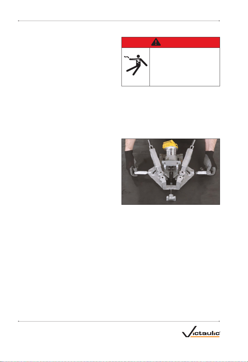
1. Prevent back injury. Always use proper
lifting techniques when handling tool
components.
2. Wear proper apparel. Do not wear loose
clothing, jewelry, or anything that can
become entangled in moving parts.
3. Wear protective items when working with
tools. Always wear safety glasses, foot
protection, and hearing protection.
4. Keep hands and tools away from cutter
bit and rollers during the grooving
operation. Grooving area can crush or cut
fingers and hands.
5. Do not reach inside the pipe ends during
tool operation. Pipe edges can be sharp
and can snag gloves, hands, and shirt
sleeves.
6. Do not make any modifications to the
tool. Do not remove any safety features
or any components that would affect tool
performance.
CAUTION
1. Inspect the equipment. Before using the
tool, check all moveable parts for any
obstructions. Ensure that tool components
are installed and adjusted properly.
2. Stay alert. Do not operate the tool if you
are drowsy from medication or fatigue.
3. Keep visitors, trainees, and observers
away from the immediate work area. All
visitors should be kept a safe distance from
the equipment at all times.
4. Keep work areas clean. Keep the
work area around the tool clear of any
obstructions that could limit the movement
of the operator. Clean up any oil or other
spills.
5. Secure the work, tool, and accessories.
Ensure that the tool is stable. Refer to the
“Tool Set Up” section.
6. Support the work. Pipe should be
supported by a pipe stand that is secured
to the floor or to the ground.
7. Do not force the tool. Do not force the tool
or accessories to perform any functions
beyond the capabilities described in these
instructions. Do not overload the tool.
8. Maintain tool with care. Keep the tool
clean at all times to ensure proper and
safe performance. Follow the instructions
for servicing tool components.
9. Use only Victaulic replacement parts
and accessories. Use of any other parts
may result in a voided warranty, improper
operation, and hazardous situations.
10. Do not remove any labels from the tool.
Replace any damaged or worn labels.
REV_C
TM- CG1100 / Operating and Maintenance Instructions Manual
TM -CG1100_5

INTRODUCTION
NOTICE
• Drawings and/or pictures in this manual
may be exaggerated for clarity.
• The tool, along with this operating
and maintenance instructions manual,
contains trademarks, copyrights, and/or
patented features that are the exclusive
property of Victaulic Company.
The Victaulic CG1100 CPVC/PVC Cut Grooving
Tool is a portable tool for cut grooving CPVC
and PVC pipe to to be compatible with Victaulic
grooved piping products. The standard CG1100
tool is equipped to groove 2–12 inch/DN50-
DN300 CPVC and PVC pipe to Victaulic’s
proprietary PGS-300 groove specifications.
This tool should only be used to groove
pipe with specifications that fall within the
designated parameters.
CAUTION
• This tool must be used ONLY for grooving
pipe with specifications that fall within
the designated parameters.
Failure to follow these instructions could
damage the tool and cause product failure,
resulting in property damage or personal
injury.
RECEIVING THE TOOL
The CG1100 Cut Grooving Tool is packed in
a sturdy box that is designed for repeated
shipping. Save the original container for return
shipment of rental tools.
Upon receipt of the tool, ensure that all
necessary parts are included. If any parts are
missing, contact Victaulic.
CONTAINER CONTENTS
Qty. Description
1CG1100 Tool
2Handle
1Set of Tool Arms (2–4 inch)*
1Set of Tool Arms (6–12 inch)*
2Cutter Bit (2–4 inch)
2Cutter Bit (6–12 inch)
1Alignment Block (2–4 inch)
1Alignment Block (6–12 inch)
2Batteries
1Battery Charger
1Flathead Screwdriver
1 ⁄-inch Wrench
1 ⁄-inch T-Handle Hex Key
1Go/No-Go Groove Diameter Cable
1Operating and Maintenance Instructions Manual
1Motor Instructions Manual
* One set of tool arms will be installed on the tool. The second
set will be included in the tool box.
RETURNING THE TOOL
When packing the tool for return shipping,
ensure that the handles, bits, and alignment
blocks are removed and secured. The bits
must be returned to their original packaging to
protect the blades. Hand tools must be secured
separately.
TM-CG1100_6 REV_C
TM- CG1100 / Operating and Maintenance Instructions Manual

POWER REQUIREMENTS
DANGER
• To reduce the risk of electric
shock, check the electrical
source for proper grounding.
• Before performing any
maintenance on the tool,
disconnect the battery from
the tool.
Failure to follow these instructions could
result in death or serious personal injury.
The CG1100 tool connects directly to a 20V
Max, 6.0 Ah lithium ion battery pack for
cordless operation.
A spare battery and charger are provided with
the tool. Keep the spare battery charged for
uninterrupted use of the CG1100 tool.
WARNING
• Do not use batteries that have been
damaged or modified.
• Do not substitute alternate batteries.
Contact Victaulic for additional batteries.
Consult the battery manufacturer’s
documentation for additional information.
TEMPERATURE REQUIREMENTS FOR
CHARGING BATTERIES
Do not charge batteries at ambient
temperatures below 40° F/ 5°C or above
105° F/ 41° C.
TEMPERATURE REQUIREMENTS FOR
TOOL
Do not use or store the tool at ambient
temperatures above 105° F/ 40° C.
BATTERY AND CHARGER
INFORMATION
Battery Charger Input (AC 120 volts, 50-60 Hz)
Battery Charger Output (DC 12 volts – 20 volts)
The battery must be charged completely before
attempting to groove pipe. Only the battery
charger supplied with the tool should be used.
Refer to the “Temperature Requirements for
Charging Batteries” section.
1a. Plug the battery charger into a proper AC
power source.
1b. Insert the battery into the battery charger.
1c. When a battery is inserted into the
battery charger, the red indicator light will
blink on and off. When charging is
complete, the red indicator light will
remain on continuously. Always refer to the
instruction sheet supplied with the battery
charger for complete information.
2. Remove the battery from the battery
charger.
3. After charging a battery, always unplug the
battery charger from the AC power source.
If the battery is not charged sufficiently at the
beginning of a grooving operation, or if the
battery runs low during grooving operation,
the tool may not complete the groove to
specification. The battery must be charged or
replaced with a fully-charged battery before
grooving resumes.
The battery must be removed when the tool is
not in use.
REV_C
TM- CG1100 / Operating and Maintenance Instructions Manual
TM -CG1100_7

TOOL NOMENCLATURE
NOTICE
• Drawings and/or pictures in this manual may be exaggerated for clarity.
• The tool, along with this operating and maintenance instructions manual, contains
trademarks, copyrights, and/or patented features that are the exclusive property of
Victaulic.
Battery
Toggle Clamp
Handle
Arm
Locking
Knob
“A”
Adjustment
Screw
and Wingnut
Arm Arm
Pipe Stop Pipe Stop
OD Roller
OD Roller
ID Roller
ID Roller
Depth Adjustment
Screw
Motor Carriage
Adjustment Knob
Motor Fixture Stop
Backing
Plate
Motor
Motor
Carriage
Toggle Clamp
Handle
Arm
Locking
Knob
Battery
Motor
Fixture
Cutter
Bit
Depth
Stop
TM -CG1100_8 REV_C
TM- CG1100 / Operating and Maintenance Instructions Manual

TOOL DIMENSIONS AND SPECIFICATIONS
17.27 in/
438.7 mm
18.11 in/
460.0 mm
7.51 in/
190.7 mm
Tool weight is 20.7 pounds/9.4 kilograms when using 2–4 inch arms, and 21.9 pounds/
9.9 kilograms when using 6–12 inch arms. Tool weight includes the tool assembly, motor, handles,
and arms.
REV_C
TM- CG1100 / Operating and Maintenance Instructions Manual
TM -CG1100_9

PIPE SET UP
All coarse scale, dirt, and other foreign material
must be removed from the interior and exterior
surfaces of the pipe ends.
PIpe ends must be square cut from the
centerline and have a square face. Chamfered
or beveled pipe may only be used if it complies
with the requirements on pages 28–30 of this
manual.
Select a location for the grooving operation by
taking into consideration the following factors
(refer to “Tool Dimensions And Specifications”
for overall dimensions):
a. Adequate space to handle pipe
lengths
b. A firm and level surface for the
pipe stand(s)
c. Anchoring requirements for the pipe
stand(s)
Pipe must be secured with a pipe stand or
similar restraint to prevent movement. The
system used must be capable of bearing the
weight of the tool (see “Tool Dimensions and
Specifications”) in addition to the weight of the
pipe being grooved.
Position the pipe to overhang the pipe stand by
approximately 8 inches/203 mm so that the pipe
stand will not obstruct the grooving process.
TOOL SET UP
DANGER
• DO NOT connect the battery
until instructed otherwise.
Failure to follow this
instruction could result in
serious personal injury.
The CG1100 tool is intended for field or shop
set up.
1. Remove all components from the packaging,
and ensure that all necessary items are
included. Refer to the “Receiving the Tool”
section. If any parts are missing, contact
Victaulic.
2. While supporting the tool on a level surface,
screw the handles into the sides of the tool until
hand-tight. Do not overtighten.
3. Determine the pipe size to be grooved,
then refer to the corresponding section for
appropriate setup instructions.
TM-CG1100_10 REV_C
TM- CG1100 / Operating and Maintenance Instructions Manual

SETUP FOR 2–4 INCH PIPE
2–4 Inch Arm Set Up
1. Unscrew and remove the arm locking knobs.
2. Loosen and remove the shoulder bolts using
the provided hex key.
3. Pull the 6–12 inch arms straight out from
the body of the tool. When not in use, store the
arms in the provided tool box.
4. The 2–4 inch arms must be mounted on the
tool in a specific orientation. Match the “A” or
“B” etched on the arm with the corresponding
letter on the tool body, then insert the arms into
the tool body so that the matching letters face
each other.
5. Replace and tighten the shoulder bolts to
finger-tight.
REV_C
TM- CG1100 / Operating and Maintenance Instructions Manual
TM -CG1100_11

6. Replace the arm locking knobs and screw
down until the arms are secure against the body
of the tool.
7. Tighten the shoulder bolts using the provided
hex key.
8. Using the motor carriage adjustment knob,
verify that the bit is positioned high enough
to clear the pipe OD when mounting the tool.
Rotate the knob counterclockwise to raise the
bit and clockwise to lower the bit.
The bit should not touch the pipe during
mounting or dismounting. This will prevent the
bit from being chipped and protect the integrity
of the gasket sealing surface.
2–4 Inch “A” Dimension Set Up
1. Loosen the wing nut on the “A” adjustment
screw, located on the front of the tool.
2. Using a flat-head screwdriver, rotate the “A”
adjustment screw counterclockwise to adjust the
groove location.
No Gap
Gap
3. Adjust the ‘A’ adjustment screw so that the
back edge of the motor fixture is drawn firmly
against the motor carriage with no gap. There
should be a gap between the front edge of the
motor fixture and the motor fixture stop.
TM -CG1100_12 REV_C
TM- CG1100 / Operating and Maintenance Instructions Manual

4. Tighten the wing nut on the “A” adjustment
screw, located on the front of the tool.
2–4 Inch Cutter Bit Setup
1. Retrieve the 2” THRU 4” alignment block.
Alignment blocks are etched with the pipe size
in inches.
WARNING
• This tool uses a multi-blade
cutter bit. Handle the bit
with care.
• The cutter bit may be hot
after grooving. Do NOT
handle the bit immediately
after grooving.
Failure to follow these
instructions could result in
serious personal injury.
2a. Retrieve the 2–4 inch cutter bit from its
packaging. Retain the packaging for future storage.
WARNING
• The bits shipped with the CG1100 tool
have a custom radius for grooving. Do
not substitute off-the-shelf square bits.
Always use bits provided by Victaulic.
Failure to follow these instructions will
cause improper product assembly and joint
failure, and could result in serious personal
injury and property damage.
2b. Take note of the line etched on the base
of the bit. This marks the minimum depth of
insertion when installing the bit into the tool.
NOTICE
• Do not lock the collet if no bit is
installed. This can damage the collet.
• Do not lock the collet before the bit has
been aligned, as shown in the following
steps.
REV_C
TM- CG1100 / Operating and Maintenance Instructions Manual
TM -CG1100_13

3. While pressing the spindle lock button, use
the ⁄-inch wrench to loosen the collet. Remove
the 6–12 inch bit.
4. Insert the 2–4 inch cutter bit into the collet to
just past the minimum insertion depth.
5. While pressing the spindle lock button, use
the ⁄-inch wrench to tighten the collet. Do not
overtighten.
6. Verify that the cutter bit is inserted deeply
enough for the etched line to be partially or fully
covered by the collet.
TM -CG1100_14 REV_C
TM- CG1100 / Operating and Maintenance Instructions Manual

7. Use the provided ⁄-inch T-Handle hex key
to loosen the set screw. This will allow the depth
stop to move.
8. Align the notch on the back of the alignment
block with the depth stop behind the bit. Slide
the alignment block over the depth stop until
fully seated.
9a. Select the appropriate cutter bit location by
matching the pipe size to the corresponding line
on the alignment block.
NOTICE
• Ensure that it is the TIP of the bit that is
meeting the line on the alignment block,
rather than a radiused corner or other edge
of the bit. Visually confirm the accuracy of
this adjustment from all angles.
9b. To set the depth stop, use the provided
⁄-inch T-Handle hex key to turn the adjustment
screw, which will move the depth stop back and
forth. Align the tip of the cutting bit with the line
on the alignment block that matches the pipe
size to be grooved.
Turning the screw clockwise will produce a
shallower groove and result in a larger “C”
dimension. Turning the screw counterclockwise
will produce a deeper groove and result in a
smaller “C” dimension. One quarter turn of the
depth adjustment screw will move the smaller
indicator mark on the groove diameter cable by
one complete width.
REV_C
TM- CG1100 / Operating and Maintenance Instructions Manual
TM -CG1100_15

9c. Verify the alignment of the tip of the cutter
bit with the appropriate line on the alignment
block. The cutter bit pictured above is set for
2.5 to 4-inch pipe.
10. Remove the alignment block and store it in
the provided tool box.
11. Hold the ⁄-inch hex key in the adjustment
screw to stop any movement and tighten the set
screw to lock the depth stop in place.
Consult the motor manufacturer’s
documentation for further information.
SETUP FOR 6–12 INCH PIPE
6–12 Inch Arm Set Up
1. Unscrew and remove the arm locking knobs.
2. Loosen and remove the shoulder bolts using
the provided hex.
3. Pull the 2–4 inch arms straight out from the
body of the tool. When not in use, store the
arms in the provided tool box.
TM-CG1100_16 REV_C
TM- CG1100 / Operating and Maintenance Instructions Manual

4. The 6–12 inch arms are interchangeable
and may be mounted on the tool in either
orientation. Insert the arms into the body of the
tool.
5. Replace and tighten the shoulder bolts to
finger-tight.
6. Replace the arm locking knobs and screw
down until the arms are secure against the body
of the tool.
7. Tighten the shoulder bolts using the provided
hex key.
8. Using the motor carriage adjustment knob,
verify that the bit is positioned high enough
to clear the pipe OD when mounting the tool.
Rotate the knob counterclockwise to raise the
bit and clockwise to lower the bit.
The bit should not touch the pipe during
mounting or dismounting. This will prevent the
bit from being chipped and protect the integrity
of the gasket sealing surface.
REV_C
TM- CG1100 / Operating and Maintenance Instructions Manual
TM -CG1100_17

6–12 Inch “A” Dimension Set Up
1. Loosen the wing nut on the “A” adjustment
screw, located on the front of the tool.
2. Using a flat-head screwdriver, rotate the “A”
adjustment screw clockwise to adjust the groove
location.
Gap
No Gap
3. Adjust the “A” adjustment screw so that the
front edge of the motor fixture is drawn firmly
against the motor fixture stop with no gap.
There should be a gap between the back edge
of the motor fixture and the motor carriage.
4. Tighten the wing nut on the “A” adjustment
screw, located on the front of the tool.
6–12 Inch Cutter Bit Setup
1. Retrieve the 6” THRU 12” alignment block.
Alignment blocks are etched with the pipe size
in inches.
WARNING
• This tool uses a multi-blade
cutter bit. Handle the bit
with care.
• The cutter bit may be hot
after grooving. Do NOT
handle the bit immediately
after grooving.
Failure to follow these
instructions could result in
serious personal injury.
TM -CG1100_18 REV_C
TM- CG1100 / Operating and Maintenance Instructions Manual

2a. Retrieve the 6–12 inch cutter bit from its
packaging. Retain the packaging for future storage.
WARNING
• The bits shipped with the CG1100 tool
have a custom radius for grooving. Do
not substitute off-the-shelf square bits.
Always use bits provided by Victaulic.
Failure to follow these instructions will
cause improper product assembly and joint
failure, and could result in serious personal
injury and property damage.
2b. Take note of the line etched on the base
of the bit. This marks the minimum depth of
insertion when installing the bit into the tool.
NOTICE
• Do not lock the collet if no bit is
installed. This can damage the collet.
• Do not lock the collet before the bit has
been aligned, as shown in the following
steps.
3. While pressing the spindle lock button, use
the ⁄-inch wrench to loosen the collet. Remove
the 2–4 inch bit.
4. Insert the 6–12 inch cutter bit into the collet
to just past the minimum insertion depth.
REV_C
TM- CG1100 / Operating and Maintenance Instructions Manual
TM -CG1100_19

5. While pressing the spindle lock button, use
the ⁄-inch wrench to tighten the collet. Do not
overtighten.
6. Verify that the cutter bit is inserted deeply
enough for the etched line to be partially or fully
covered by the collet.
7. Use the provided ⁄-inch T-handle hex key
to loosen the set screw. This will allow the depth
stop to move.
8. Align the notch on the back of the alignment
block with the depth stop behind the bit. Slide
the alignment block over the depth stop until
fully seated.
TM -CG1100_20 REV_C
TM- CG1100 / Operating and Maintenance Instructions Manual
Table of contents
Other Victaulic Cutter manuals