Summa S Class 2 OPOS-CAM User manual

The information contained in this document is confidential, and only for the information of the intended recipient and may not be published or redistributed without the prior written consent of Summa NV.
Summa nv Tel +32 59 27 00 11 Fax +32 59 27 00 63 Email [email protected] Website www.summa.com Page 1 of 76
S Class 2 Troubleshooting Guide
There may be occasions in which the machine does not operate as it should work, or an
error message is displayed on the screen. This document may help you to find the cause of
the issue, and a way to solve the problem.
Revision history
August 22, 2018 Document created
March 2, 2020 Added hyperlinks to external documents
March 31, 2020 Added “Ticking sound” issue
July 31, 2020 Changed summa.eu to summa.com
August 24, 2020 Added “Media crashes in basket”
November 23, 2020 Document name change from “S Class 2 Machine Issues” to “S Class 2 Troubleshooting”
May 31, 2021 Added roll-up wiring diagram
Revised May 31, 2021

The information contained in this document is confidential, and only for the information of the intended recipient and may not be published or redistributed without the prior written consent of Summa NV.
Summa nv Tel +32 59 27 00 11 Fax +32 59 27 00 63 Email [email protected] Website www.summa.com Page 2 of 76
Table of Contents
1Introduction...................................................................................................... 6
2Error Messages................................................................................................. 6
2.1 Y-axis error! Overflow! .............................................................................................6
2.2 X-axis error! Overflow!.............................................................................................7
2.3 Up-Down encoder not working ................................................................................8
2.4 Cutter is unable to find the knife home position ................................................... 10
2.5 Turn power off! Pinch rollers are not found .......................................................... 11
2.6 The middle pinch roller is not set properly above a sleeve!...................................13
2.7 The left pinch roller is not set properly above a sleeve! ........................................13
2.8 Unable to lower OPOS! .......................................................................................... 14
2.9 This media probably cannot be sensed properly...................................................15
2.10 Unlocking OPOS Barcode failed! .........................................................................15
2.11 Unable to sense OPOS Barcode! .........................................................................16
2.12 Activation of the G-Performance Mode failed! ................................................... 17
2.13 Flash device not found!...................................................................................... 17
2.14 No memory for DMPL-buffer! Reboot… ............................................................. 17
2.15 No memory for display-stack! Reboot… .............................................................18
3Other messages.............................................................................................. 18
3.1 Digitize origin.........................................................................................................18
3.2 Digitize point..........................................................................................................18
4Wrong behavior .............................................................................................. 18
4.1 Machine does not start ..........................................................................................18
4.2 Media does not load...............................................................................................19
4.3 Media not detected................................................................................................20
4.4 Media crashes in basket ........................................................................................21
4.5 Machine freezes.....................................................................................................22
4.6 Knife keeps spinning .............................................................................................22

The information contained in this document is confidential, and only for the information of the intended recipient and may not be published or redistributed without the prior written consent of Summa NV.
Summa nv Tel +32 59 27 00 11 Fax +32 59 27 00 63 Email [email protected] Website www.summa.com Page 3 of 76
4.7 Knife drops on media or cutting strip when machine is switched off.....................23
4.8 Drive drum keeps spinning ....................................................................................24
4.9 Random reloading media.......................................................................................24
4.10 Random reboot...................................................................................................25
4.11 Display too bright ...............................................................................................25
4.12 White line in display............................................................................................26
4.13 Flashing display..................................................................................................26
4.14 Display reacts incorrectly ...................................................................................27
4.15 Vacuum fan does not work .................................................................................28
4.16 OPOS sensor makes repeated up down movements ..........................................29
4.17 OPOS sensor starts searching 1 cm above mark ................................................29
4.18 Cutting stops after first panel.............................................................................29
4.19 Roll-up does not work.........................................................................................30
4.20 Ticking sound .....................................................................................................32
5Media transport issues..................................................................................34
5.1 Using sheet media .................................................................................................34
5.2 Using roll media.....................................................................................................34
6Cutting issues.................................................................................................39
6.1 Knife dropped in toolshaft .....................................................................................39
6.2Uneven cutting depth ............................................................................................39
6.3 Unable to change cutting pressure ...................................................................... 41
6.4 Machine cuts lines twice....................................................................................... 41
6.5 Knife scratches media ...........................................................................................42
6.6 Knife plows through media ....................................................................................43
6.7 Ragged contours ...................................................................................................43
6.8 Bad cutting quality ............................................................................................... 44
6.8.1 Drag Head issues ............................................................................................................... 45
6.9 Curves do not close .............................................................................................. 47
6.10 Horizontal shift (Y axis) ......................................................................................48

The information contained in this document is confidential, and only for the information of the intended recipient and may not be published or redistributed without the prior written consent of Summa NV.
Summa 
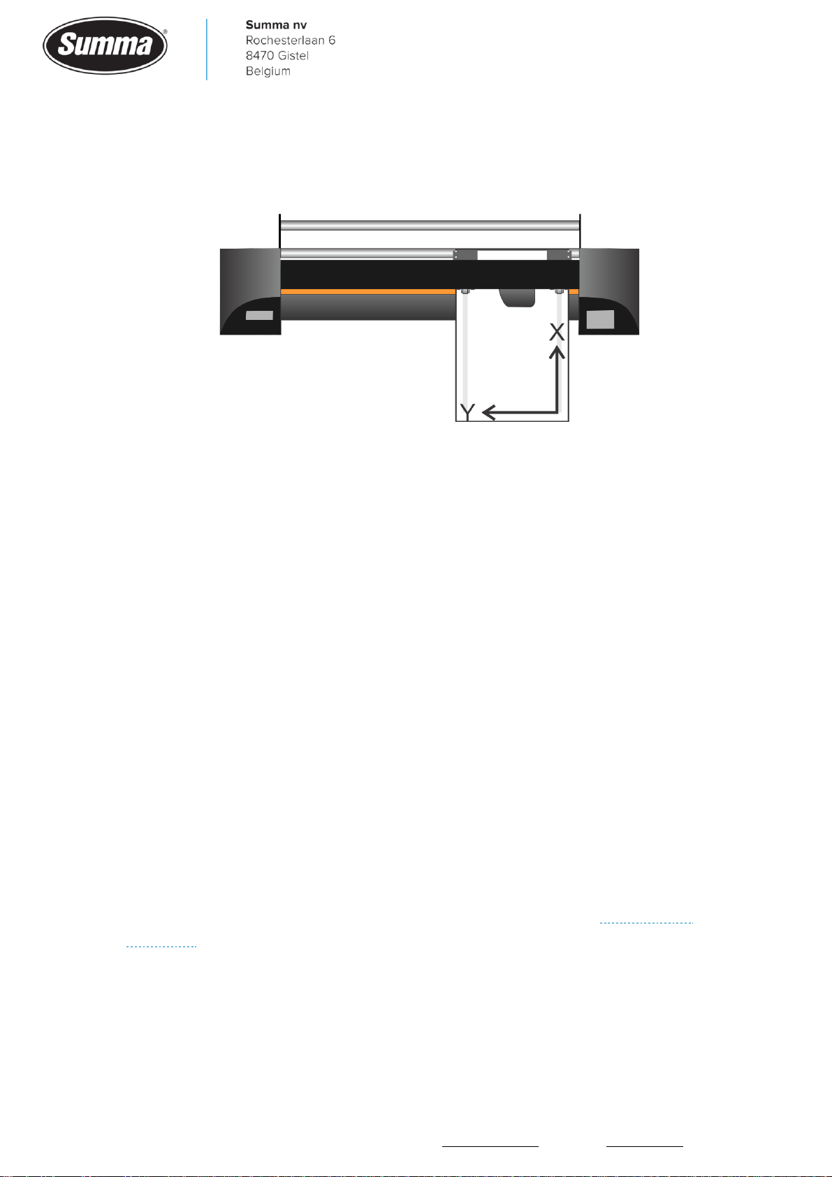
nv Tel +32 59 27 00 11 Fax +32 59 27 00 63 Email [email protected] Website www.summa.com Page 4 of 76
6.11 Vertical shift (X axis) ..........................................................................................49
6.12 Cutting stops after first panel.............................................................................50
6.13 Shift between panels ..........................................................................................50
6.14 Random lines......................................................................................................50
6.15 Jobs are too long or too short ............................................................................51
6.16 Jobs are too small or too wide ............................................................................51
7Print & Cut issues...........................................................................................52
7.1 Print & Cut shift .....................................................................................................52
7.2 OPOS registration marks not read .........................................................................55
7.3 Excessive bowing...................................................................................................56
7.4 Cutting stops after first panel................................................................................57
8Communication issues..................................................................................59
8.1 USB Interface ........................................................................................................60
8.2 Network interface ..................................................................................................62
8.2.1 Error messages.................................................................................................................. 63
9Menu Structure ..............................................................................................64
9.1 Service mode .........................................................................................................64
9.2 Settings .................................................................................................................64
9.3 Actions...................................................................................................................65
9.4 Service...................................................................................................................65
10 Diagnostics .....................................................................................................66
10.1 Procedure...........................................................................................................66
10.2 Sensors monitored .............................................................................................67
10.2.1 X-encoder ......................................................................................................................... 67
10.2.2 Y-encoder ......................................................................................................................... 67
10.2.3 Z-motor .......................................................................................................................... 67
10.2.4 UD-encoder .................................................................................................................... 68
10.2.5 Front sensor ................................................................................................................... 68
10.2.6 Back sensor.................................................................................................................... 68

The information contained in this document is confidential, and only for the information of the intended recipient and may not be published or redistributed without the prior written consent of Summa NV.
Summa nv Tel +32 59 27 00 11 Fax +32 59 27 00 63 Email [email protected] Website www.summa.com Page 5 of 76
10.2.7 OPOS sensor................................................................................................................... 68
10.2.8 Cam sensor .................................................................................................................... 69
10.2.9 Ultrasonic sensor ........................................................................................................... 69
10.2.10 Cam switch .....................................................................................................................71
10.3 Worn X-motor detection .................................................................................... 71
10.4 Main board connectors.......................................................................................73
10.5 Cutter head connectors......................................................................................76

The information contained in this document is confidential, and only for the information of the intended recipient and may not be published or redistributed without the prior written consent of Summa NV.
Summa nv Tel +32 59 27 00 11 Fax +32 59 27 00 63 Email [email protected] Website www.summa.com Page 6 of 76
1Introduction
In this document, when mentioning the X-axis or Y-axis, then the X-axis is the feeding
direction of the media, and the Y-axis is the movement of the cutter head.
2Error Messages
When an unexpected problem occurred then an error message is displayed on the touch
screen of the machine.
2.1 Y-axis error! Overflow!
When the cutter head cannot be moved to the commanded position, then this error message
is displayed.
This error message may also be displayed at startup of the machine, as the cutter head is
then moved to the right side of the machine. When starting the machine in service mode,
then the cutter head is not moved to the right side. The error message will then not be
displayed.
The error message could be displayed because of the following:
•Mechanical obstruction of the cutter head carriage: this may be caused by a media crash.
When the machine is switched off, the cutter head should be able to be moved left and right
smoothly.
•Defective encoder on the Y-axis motor. Usually the cutter head will stall, or be fed at a high
speed. Functionality can be checked from the “Monitor” display, see Service mode and
Y-encoder.
•Defective Y-axis motor.

The information contained in this document is confidential, and only for the information of the intended recipient and may not be published or redistributed without the prior written consent of Summa NV.
Summa nv Tel +32 59 27 00 11 Fax +32 59 27 00 63 Email [email protected] Website www.summa.com Page 7 of 76
•Defective driver (U24) on the main board. Replace the main board.
•Wires not firmly seated in the motor connector.
•Motor connectors not sufficient seated in the sockets on the main board.
•Worn belts used to drive the cutter head. See also “Curves do not close”.
•Machine type has been set incorrect. Click to verify machine type.
•The system parameter “num_camrollers” is set incorrect: set to 0 for a standard machine, or
set to exact amount of pinch rollers in the machine when additional pinch rollers were added
or removed.
2.2 X-axis error! Overflow!
When media is loaded, and cannot be moved to the commanded position, then the error
message is displayed. When the machine is switched off, and no media loaded with the pinch
rollers lifted, the drive drum should be able to be rotated by hand smoothly.
The error message could be displayed because of the following issues:
•Autoload was disabled whilst using roll media. Set “Autoload” to ON: click [Settings] – [More]
– [General] – [Autoload], select “ON” and confirm.
•Mechanical obstruction of the drive drum: check the media, check for parts jammed between
grit rollers and base plate.
•Defective encoder on the X-axis motor. Usually the media will stall, or be fed at a high speed.
Functionality can be checked from the “Monitor” display, see Service mode and X-encoder.
•Worn X-motor(s).

The information contained in this document is confidential, and only for the information of the intended recipient and may not be published or redistributed without the prior written consent of Summa NV.
Summa nv Tel +32 59 27 00 11 Fax +32 59 27 00 63 Email [email protected] Website www.summa.com Page 8 of 76
•Defective driver (U22 or U23) on the main board. Usually the media does not move. Replace
the main board.
•Wires not firmly seated in the motor connector.
•Motor connectors not sufficient seated in the sockets on the main board.
•The X-belts may be worn, or on wider machines (120, 140 and 160) the two belts on the drive
drum pulley may be too close to each other. See also “Vertical shift (X axis)”.
2.3 Up-Down encoder not working
The error message for a bad up/down encoder is displayed when the machine cannot detect
the knife goes up and down. Functionality of the up/down encoder is checked during the
media load sequence.
When the machine is switched off, the knife should be able to be lowered and lifted
smoothly.
Functionality can be checked from the “Monitor” display, see Service mode and UD-encoder.
The error message could be displayed because of the following issues:
•Media crash prevents the knife going up and down.
•Mechanical issue preventing the knife going up or down: replace the cutter head.
•Up/down encoder sensor defective: replace the cutter head.
•Up/down encoder strip defective: replace the cutter head.
•Coil in the cutter head defective (open or short circuit, resistance should be around 15 ohms),
because of this the knife does not go up or down: replace the cutter head.

The information contained in this document is confidential, and only for the information of the intended recipient and may not be published or redistributed without the prior written consent of Summa NV.
Summa nv Tel +32 59 27 00 11 Fax +32 59 27 00 63 Email [email protected] Website www.summa.com Page 9 of 76
•Connector for the coil (J1) came loose.
•Flat cable interrupted causing the knife not going up and down: replace the flat cable.
•Flat cable not firmly seated in the connector. Check on main board (J22: HEAD1) and on cutter
head (J5).

The information contained in this document is confidential, and only for the information of the intended recipient and may not be published or redistributed without the prior written consent of Summa NV.
Summa nv Tel +32 59 27 00 11 Fax +32 59 27 00 63 Email [email protected] Website www.summa.com Page 10 of 76
•Driver U27 on the main board defective, because of this the knife does not lower: Replace the
main board.
2.4 Cutter is unable to find the knife home position
Right after loading media, when the cutter head went back to the right side edge of the
media, the knife rotates to find its home position (origin). In case the knife home position
could not been found, then the error message is displayed.
When the machine is switched off, the knife holder should be able to be rotated smoothly.
The error message will be displayed due to the following:
•The knife does not rotate due a mechanical obstruction (e.g. worn bearing in the tool shaft).
The knife holder should be able to be rotated smoothly when the machine is switched off.
Replace the cutter head.
•The motor in the cutter head used to rotate the knife may be defective. The knife holder
should be able to be rotated smoothly when the machine is switched off. Replace the cutter
head.
•The encoder of the motor in the cutter head is defective. Functionality can be checked from
the “Monitor” display, see Service mode and Z-motor. Replace the cutter head.
•The flat cable used between the cutter head and the main board may be defective. Replace the
flat cable.

The information contained in this document is confidential, and only for the information of the intended recipient and may not be published or redistributed without the prior written consent of Summa NV.
Summa nv Tel +32 59 27 00 11 Fax +32 59 27 00 63 Email [email protected] Website www.summa.com Page 11 of 76
•The driver (U28) on the main board may be defective and because of this the knife does not
rotate. Replace the main board.
•Flat cable or motor cable not firmly seated in the connector. Check on main board (J21:
HEAD2) and on cutter head (J7 and J9) and correct if necessary.
2.5 Turn power off! Pinch rollers are not found
On loading media, and lowering the pinch rollers, the machine starts to search for the
position of the pinch rollers. The cutter head is moved up to the right side end plate to use

The information contained in this document is confidential, and only for the information of the intended recipient and may not be published or redistributed without the prior written consent of Summa NV.
Summa nv Tel +32 59 27 00 11 Fax +32 59 27 00 63 Email [email protected] Website www.summa.com Page 12 of 76
this as the reference position. Then the cutter head moves to the left to search the first
pinch roller position. In case the pinch roller sensor does not work, then the carriage moves
slowly to the left to scan for the first pinch roller for about 10 cm, and then the error
message is displayed. Functionality can be checked from the “Monitor” display, see
Service mode and Cam sensor.
•Check for strong light interfering with the pinch roller sensor, e.g. when the cutter is near a
window and direct sunlight is on the machine.
•Check for dirt on the pinch roller sensor, use compressed air to remove dust.
•The pinch roller sensor may be defective, or the connector (J8) for the sensor came loose
from the socket, or has a bad contact. Replace the pinch roller sensor.

The information contained in this document is confidential, and only for the information of the intended recipient and may not be published or redistributed without the prior written consent of Summa NV.
Summa nv Tel +32 59 27 00 11 Fax +32 59 27 00 63 Email [email protected] Website www.summa.com Page 13 of 76
•The flat cable between the cutter head (J5) and the main board (J22: HEAD1) may be
defective, or the flat cable was not fit straight in the sockets. Replace the flat cable.
•The main board may be defective. Replace the main board.
2.6 The middle pinch roller is not set properly above a sleeve!
2.7 The left pinch roller is not set properly above a sleeve!
On loading media, and lowering the pinch rollers, the machine starts to search for the
position of the pinch rollers. The cutter head is moved up to the right side end plate to use
this as the reference position. Then the cutter head moves to the left to search the first
pinch roller position. It then searches for the middle pinch rollers, and finally for the left-
most pinch roller.
The machine may incorrectly detect the position of the middle and/or left-most pinch rollers
being set incorrectly. This could be due to the following:
•Double check for the left and/or middle pinch rollers to have been put in a click position (over
a grit roller) indicated by a small white triangle on the Y-axis guiding.

The information contained in this document is confidential, and only for the information of the intended recipient and may not be published or redistributed without the prior written consent of Summa NV.
Summa nv Tel +32 59 27 00 11 Fax +32 59 27 00 63 Email [email protected] Website www.summa.com Page 14 of 76
•Check for strong light interfering with the pinch roller sensor, e.g. when the cutter is near a
window and direct sunlight is on the machine.
•On start of media loading, the cutter head should bounce to the right side as a reference.
Probably a mechanical obstruction prevents the cutter head going to the full right side,
causing the machine to use a wrong reference for detecting placement of the pinch rollers.
•The Y-belts may be worn. This causes the belt to jump over the teeth of the pulley. As a result
a wrong position is detected. To check for a worn Y-belt, move the cutter head completely to
the right side until the cut off mechanism touches the right side tab, then apply a mark on the
double pulley and belts. Run some jobs, and when a shift is suspected, move the cutter head
to the full right side, and verify the dots on the belt and pulley to match.
•The Y axis calibration may be off, causing the machine to assume the pinch rollers are at a
wrong position. Recalibrate the Y-axis: start the machine in service mode (see
“Service mode”), load media, then click [Settings] – [More] – [Calibrate X-Y].
•The pulley on the Y-motor may be loose.
•The encoder on the Y-motor may be defective causing to lose steps. Replace the Y-motor.
•The machine type has been set incorrect. Start the machine in service mode, confirm
[SERVICE MODE], then click [SERVICE] – [Machine type] and set the machine type correct to
match the hardware.
2.8 Unable to lower OPOS!
When the machine has to read the position of the OPOS registration marks, then the OPOS
sensor has to be lowered to the media to have a good focus of the light beam used. To lower
the OPOS sensor the knife is lifted to the upmost position. This position is controlled and
checked by means of the linear encoder (up/down encoder) in the cutter head. In case the
machine detects the knife cannot be lifted sufficient enough, then the up/down movement is

The information contained in this document is confidential, and only for the information of the intended recipient and may not be published or redistributed without the prior written consent of Summa NV.
Summa nv Tel +32 59 27 00 11 Fax +32 59 27 00 63 Email [email protected] Website www.summa.com Page 15 of 76
repeated a few times. In case after some retries the up movement was still not successful,
the error message is displayed.
There may be different reasons for this problem:
•The cutter head height is set incorrect. On use of the white nose piece, a gap of 2.8 mm
should exist between the rollers of the nose piece and the cutting strip.
•There may be some friction in the cutter head requiring the coil to have more power to be able
to lower the OPOS sensor: increase the current used to lift the knife when the OPOS sensor
has to be lowered: start the machine in service mode (see “Service mode”), then click
[Service] – [System registers]. Scroll down in the list for the parameter “lower_OPOS_press2”
and set the value to 210.
2.9 This media probably cannot be sensed properly
When there is insufficient contrast between the color used to print the registration markers,
and the media, then the OPOS sensor is unable to detect the position of the registration
markers. Check the following:
•The OPOS sensor has to be free of dirt. Remove vinyl residue from the bottom of the sensor.
Remove dust from the optics.
•The OPOS sensor may not completely touch the media while calibrating the media. This could
be due to insufficient slack of the wires between the OPOS sensor and the PCB on the cutter
head. See “OPOS registration marks not read”.
•The OPOS sensor may need to be calibrated using the potentiometers on the cutter head
board. See document OPOS-X Sensor Calibration.
•When using silver media, use a yellow filter. See document OPOS-X with Reflective Media.
•When using colored media, try another color for the registration marks.
•The OPOS sensor may be defective. Replace the OPOS sensor.
•The media may not be compatible with the OPOS sensor. Try printing a white area around (and
under) the registration mark.
2.10 Unlocking OPOS Barcode failed!
To unlock the OPOS Barcode functionality, an activation code has to be entered. This unlock
code can be obtained by filling in a form on the Summa website:
https://www.summa.eu/en/barcode-registration, after which the unlock code is displayed
and sent by email.
In case unlocking failed, check the following:
•An incorrect serial number has been used in the registration form.

The information contained in this document is confidential, and only for the information of the intended recipient and may not be published or redistributed without the prior written consent of Summa NV.
Summa nv Tel +32 59 27 00 11 Fax +32 59 27 00 63 Email [email protected] Website www.summa.com Page 16 of 76
•An incorrect unlock code has been entered on the display of the machine.
•The serial number in the machine (main board) does not match the serial number on the serial
number tag. Click to verify the serial number defined in the main board.
2.11 Unable to sense OPOS Barcode!
When the machine is unable to read the barcode then check the following:
•The OPOS sensor will read the slope of the horizontal line. For this to read correctly, the
sensitivity of the OPOS sensor may have to be adjusted to match the media used. Click
[Settings] – [More] – [OPOS] – [Calibrate media (OPOS)] – [Set] to check current sensitivity
setting. This sensitivity setting does not affect the reading of the barcode itself.
•The OPOS sensor has to be free of dirt. Remove vinyl residue from the bottom of the sensor.
Remove dust from the optics.
•The OPOS sensor may not completely touch the media while searching for the horizontal line
or while reading the barcode. This could be due to insufficient slack of the wires between the
OPOS sensor and the PCB on the cutter head. See “OPOS registration marks not read”.
•The size of the barcode may be incorrect. Probably the job has been scaled. Width (from first
bar to last bar) should be 212 mm, height (including horizontal line) between 10.5 and 12.5
mm.
•The barcode has to fit between the two outermost pinch rollers.
•When the printer has printed vertical color bands on the right side, then this should be on the
right side of the right side pinch roller (between barcode and color bars).
•The registration marks may be too big, and are detected as being part of the barcode. Set the
rightmost pinch roller on the right side registration marks to prevent the OPOS sensor to scan
the registration mark as part of the barcode.

The information contained in this document is confidential, and only for the information of the intended recipient and may not be published or redistributed without the prior written consent of Summa NV.
Summa nv Tel +32 59 27 00 11 Fax +32 59 27 00 63 Email [email protected] Website www.summa.com Page 17 of 76
▪Barcode cannot be read due to too big registration marks:
▪By setting the pinch roller over the right side registration mark, the barcode is correctly
read:
•The distance between the last job and the next job may be too long. The machine will search
for the next barcode for 50 cm. When the next barcode is more than 50 cm from the previous
job, then the error message is displayed.
•The system parameter “s1_class” was set to 1. In this case the sensor is not dropped on the
media and hovers over the media while searching for the registration marks. Start the machine
in service mode, click [SERVICE MODE] – [SERVICE] – [System registers] and set the system
parameter “s1_class” to zero.
2.12 Activation of the G-Performance Mode failed!
To activate the G-Performance mode, an activation code has to be entered. This activation
code can be obtained by filling in a form on the Summa website:
https://www.summa.eu/en/g-performance, after which the activation code is displayed and
sent by email.
In case activation failed, check the following:
•An incorrect serial number has been used in the registration form.
•An incorrect activation code has been entered on the display of the machine.
•The serial number in the machine does not match the serial number on the serial number tag.
Click to verify the serial number defined in the main board.
2.13 Flash device not found!
The error message may appear during the upgrade of the firmware. This indicates the
memory holding the firmware of the cutter became unavailable. As this is a fatal error, the
main board may have to be returned to Summa for recovery (if possible), or replaced.
2.14 No memory for DMPL-buffer! Reboot…
See section 2.15.

The information contained in this document is confidential, and only for the information of the intended recipient and may not be published or redistributed without the prior written consent of Summa NV.
Summa nv Tel +32 59 27 00 11 Fax +32 59 27 00 63 Email [email protected] Website www.summa.com Page 18 of 76
2.15 No memory for display-stack! Reboot…
This error message will be displayed to indicate insufficient memory for the machine to work,
as a result of the onboard memory being defective. Replace the main board.
3Other messages
3.1 Digitize origin
See section 3.2.
3.2 Digitize point
Those messages appears to indicate the user has to set the knife tip manually over the
registration marks. This will happen when the OPOS alignment method was set to a manual
alignment method: XY-Adjustment, XY-Alignment, or X-Alignment. Change the OPOS
alignment method to an automatic method to have the OPOS sensor to read the registration
marks automatically: click [Settings] –[More] –[OPOS] –[OPOS Alignment] and select
OPOS-X, OPOS-XY, OPOS-Barcode or OPOS-XY2.
4Wrong behavior
4.1 Machine does not start
When the power switch is set to on, then after 3 seconds the Summa logo should be
displayed. Then after another 5 seconds a beep sounds to indicate the machine is ready. In
case the machine does not start, check the following items:
•No power at the wall socket. Should be between 85 and 264 V AC.
•Power cable not plugged in: check at wall plug, and at machine socket.
•Power cable defective: replace the power cable.
•Fuse in power entry module blown. Usually caused by a defective power supply.
•The power entry module may be defective.
•The power supply may be defective. A green LED on the power supply should lit up when
powered on. The power supply should deliver 48V DC to the main board.

The information contained in this document is confidential, and only for the information of the intended recipient and may not be published or redistributed without the prior written consent of Summa NV.
Summa nv Tel +32 59 27 00 11 Fax +32 59 27 00 63 Email [email protected] Website www.summa.com Page 19 of 76
•The main board may be defective. Replace the main board.
•A firmware update did not succeed, probably due to a power failure during the firmware
update. Send the main board back to Summa for recovery, or replace the main board. See also
“Flash device not found!”.
•Jumper on connector J3 missing.
•A device connected to the main board may require too much current. Disconnect all cables
(including flat cables) except the power cable (PWR) and switch the machine on. A beep
should be heard after 8 seconds. In case the machine boots with the cables disconnected,
then reconnect the cables one by one and reboot after every reconnection to determine the
device causing the problem.
4.2 Media does not load
After media has been put in the machine, and pinch rollers are lowered, then the media load
process is started: the cutter head is moved to the right side, then moves to the left to scan
the position of the pinch rollers. When all pinch roller positions are detected, the cutter head
moves to the right side of the media, lifts and lowers the knife to check for the up/down
encoder to determine the knife height and OPOS sensor height. When Autoload was
activated, media is fed and shaken to determine media weight and friction in order to
determine motor parameters and to create a micro-sprocket track in the rear of the media.
Finally the knife is set in a known direction. In case the load procedure does not start, check
the following:
•In case an error message is displayed, then check the section “Error Messages”.

The information contained in this document is confidential, and only for the information of the intended recipient and may not be published or redistributed without the prior written consent of Summa NV.
Summa nv Tel +32 59 27 00 11 Fax +32 59 27 00 63 Email [email protected] Website www.summa.com Page 20 of 76
•The tab on the pinch roller switch activator may be broken.
•The lever on the pinch roller switch may be bent or broken.
•Probably the switch, used to detect pinch rollers are down, is defective. To determine whether
the switch or the main board is defective, disconnect the cable from the pinch roller up/down
connector (J15) on the main board, after which the cutter should start the load procedure,
indicating the pinch roller switch is defective. In case the machine still does not start the
media load sequence, then the main board is defective.
•The machine may not have detected the pinch rollers are down. Probably the switch, used to
detect pinch rollers are down, is defective.
•Probably the media is not detected. See “Media not detected”.
4.3 Media not detected
Two media sensors are used to detect whether or not media is in the machine.
Those sensors emit infrared light which is to be reflected by the backing of the media, and
then picked up by the sensor.
When media is not correctly detected, then this could be due to the following:
•The media sensors may have collected dirt: clean the sensors.
•Machine was started in service mode (see “Service mode”): the media sensors are switched
off when the machine runs in service mode. Reboot the machine to exit service mode.
•Backing of the media does not reflect infrared light, e.g. dark colored backing. In this case the
media is not detected. To be able to use this media, switch the media sensors off: [Settings] –
[More] – [General] – [Media sensor] and set to “OFF”.
•The media sensor has been switched off. In this case the media load procedure starts as soon
as the pinch rollers are lowered, even without media in the machine. Check media sensor
settings: [Settings] – [More] – [General] – [Media sensor] and set to “ON” or to “FRONT OFF”.
Other manuals for S Class 2 OPOS-CAM
2
Table of contents
Other Summa Cutter manuals

Summa
Summa S CLASS User manual

Summa
Summa S 75 User manual

Summa
Summa SummaSign D500 User manual

Summa
Summa SummaCut D160SE User manual

Summa
Summa L1810 2nd generation User manual

Summa
Summa L1810 User manual

Summa
Summa S3 Series User manual

Summa
Summa S CLASS User manual

Summa
Summa L1810 User manual

Summa
Summa SummaSign Pro SL D-series User manual

Summa
Summa SummaCut D120 User manual

Summa
Summa S2 SERIES User manual

Summa
Summa S Class 2 OPOS-CAM User manual

Summa
Summa SUMMACUT User manual

Summa
Summa SummaCut D120 User manual

Summa
Summa S One Series User manual

Summa
Summa L1810 User manual

Summa
Summa S Class 2 OPOS-CAM User manual

Summa
Summa L3214 User manual