2
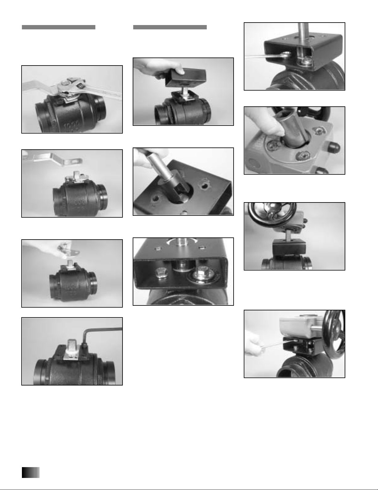
REMOVAL OF LEVER
HANDLE
To remove a lever handle for installation of a
gear operator, perform the following steps.
1.
Remove the handle assembly nut from the
lever handle, as shown above.
2.
Remove the identification tag and the
lever handle.
NOTE:
Keep the identification
tag for assembly onto the gear operator.
3.
Remove the locking plate from the valve.
4.
Using an allen wrench, remove the screw
from the mounting plate of the valve.
INSTALLATION OF
GEAR OPERATOR
ASSEMBLY
1.
Install the bracket onto the valve body by
aligning the holes of the bracket with the
holes in the mounting plate of the valve.
2.
Installthe stem adapter by positioningthe
flats of the stem adapter over the flats of the
valve stem, as shown above.
3.
Place a lock washer onto a hex-head
screw, and hand-tighten the screw into one
of the holes in the bracket and the mounting
plate of the valve. Repeat this procedure two
more times.
NOTE:
Refer to the “Required
Parts” chart on page 1 for the proper hex-
head screw size and lock washer size.
3a.
On the fourth hex-head screw, install a
flat washer, then the identification tag (with
lettering facing toward the hex head of the
screw). Hand-tighten this hex-head screw
into the final hole in the bracket and mount-
ing plate of the valve. Refer to the above
photo.
3b.
Tighten the four hex-head screws until
the lock washers are flattened.
4.
Insert the drive hub into the gear operator
by aligning the key of the drive hub with the
keyway in the gear operator, as shown
above.
5.
While supportingthe drive hub, install the
gear operator onto the stem adapter by posi-
tioning the flats of the drive hub over the
flats of the stem adapter. Make sure the indi-
cating arrow on top of the gear operator indi-
cates the correct disc position.
6.
Place a lock washer onto each of the four
hex-head screws, and hand-tighten the
screws into the holes in the bracket and the
gear operator.
NOTE:
Refer to the “Required
Parts” chart on page 1 for the proper hex-
head screw size and lock washer size.
6a.
Tighten the four hex-head screws until
the lock washers are flattened.
7.
Open and close the valve to ensure proper
operation of the gear operator.


