Victaulic VicFlex I-VICFLEX.AQD-M User manual

I-VICFLEX.AQD-MINSTALLATION INSTRUCTIONS
Victaulic®VicFlex™Sprinkler Fittings for Metal Duct Applications
Style AQD-M Bracket
I-VICFLEX.AQD-M_1
REV_B
WARNING
• Read and understand all instructions before attempting to install any Victaulic products.
• Always verify that the piping system has been completely depressurized and drained immediately prior
to installation, removal, adjustment, or maintenance of any Victaulic products.
• Confirm that any equipment, branch lines, or sections of piping that may have been isolated for/
during testing or due to valve closures/positioning are identified, depressurized, and drained
immediately prior to installation, removal, adjustment, or maintenance of any Victaulic products.
• Wear safety glasses, hardhat, and foot protection.
Failure to follow these instructions could result in death or serious personal injury and property damage.
• This Victaulic®VicFlex™product shall be used only in fire protection systems that are designed and installed in accordance with current,
applicable National Fire Protection Association (NFPA 13, 13D, 13R, etc.) standards, or equivalent standards, and in accordance with
applicable building and fire codes. These standards and codes contain important information regarding protection of systems from freezing
temperatures, corrosion, mechanical damage, etc.
• These installation instructions are intended for an experienced, trained installer. The installer shall understand the use of this product and
why it was specified for the particular application.
• The installer shall understand common industry safety standards and potential consequences of improper product installation.
• It is the system designer’s responsibility to verify suitability of stainless steel flexible hose for use with the intended fluid media within the
piping system and external environment.
• The material specifier shall evaluate the effect of chemical composition, pH level, operating temperature, chloride level, oxygen level, and
flow rate on stainless steel components to confirm system life will be acceptable for the intended service.
Failure to follow installation requirements and local and national codes and standards could compromise system integrity or cause system
failure, resulting in death or serious personal injury and property damage.
Flexible Hose Listing and Approval Information
Flexible Hose
AH2-CC With AQD-M
NOTE: Victaulic®VicFlex™flexible hoses are City of Los Angeles
(RR5659) Approved, accepted for use by the City of New York
Department of Buildings (MEA 60-05-E), and have the OSHPD Pre-
Approval (OPA-2255-07).
Maximum Working Pressure Rating of Flexible Hose:
200 psi/14 Bar/1379 kPa (FM)
Maximum Ambient Temperature Rating of Flexible Hose:
225° F/107° C (FM)
Connection to Sprinkler Piping:
1 inch/DN25 IGS (FM)
Minimum Bend Radius of Flexible Hose:
7 inch/178 mm (FM – Series AH2-CC)
Maximum K-Factor of Sprinkler to be Connected to Sprinkler
Reducing Nipple:
Refer to footnotes in the “Friction Loss Data” section.
Maximum Number of 90° Bends Per Flexible Hose:
Refer to the “Friction Loss Data” section.
Flexible Hose Bend Characteristics:
NOTE: Care shall be taken to avoid torquing the flexible hose.
90°
OR
OR
Minimum
Bend Radius
Minimum
Bend Radius Minimum
Bend Radius
Minimum
Bend Radius
Minimum
Bend Radius
Minimum
Bend Radius
Minimum
Bend Radius
2X
Minimum
Bend
Radius
2X
Minimum
Bend
Radius
SCAN QR CODE FOR ACCESS TO THE FULL
I-VICFLEX.BRG BEND RADIUS GUIDE INSTRUCTIONS
ON VICTAULIC.COM

I-VICFLEX.AQD-M_2 REV_B
I-VICFLEX.AQD-M / Victaulic®VicFlex™Style AQD-M Bracket / Installation Instructions
INTRODUCTION
Victaulic®VicFlex™Style AQD-M Brackets connect the branch line directly to the sprinkler and can be installed on round or square metal ducts.
IMPORTANT INSTALLATION INFORMATION
• Victaulic®VicFlex™products shall be installed according to current, applicable National Fire Protection Association (NFPA 13, 13D, 13R, etc.)
standards or equivalent standards and in accordance with applicable building and fire codes. Victaulic®VicFlex™products are intended to be
installed in wet, dry, or preaction actuated systems. Deviations from these standards or alterations to Victaulic®VicFlex™products or sprinklers
will void any Victaulic warranty and will impact system integrity. Installations shall meet the provisions of the local authority having jurisdiction
and local codes, as applicable, and shall comply with all design specifications.
• Victaulic® VicFlex™Sprinkler Fittings and Style AQD-M Brackets shall not be intermixed with other manufacturer’s flexible sprinkler products.
• Refer to the specific Victaulic product publication for applications and listing information. In addition, when installing Victaulic FireLock®
Automatic Sprinklers with Victaulic®VicFlex™Sprinkler Fittings, refer to the I-40 Installation and Maintenance Instructions for details on
sprinkler installation requirements. Product publications and installation instructions can be downloaded at victaulic.com.
• Size the piping system to meet or exceed the minimum required flow rate for the sprinkler system.
• Per NFPA requirements, flush the system to remove foreign material. Continue to flush the system until water runs clear.
• DO NOT install sprinkler system piping through heating ducts.
• DO NOT connect sprinkler system piping to domestic hot water systems.
• DO NOT allow electrical wiring or other cabling to be hung or wrapped around the sprinkler piping system.
• DO NOT install sprinklers and sprinkler fittings where ambient conditions may fall below or exceed the maximum listed or approved temperature
ratings.
• The flexible hose shall not be bent or fluctuated up-and-down or side-to-side when pressurized.
• Victaulic VicFlex Series AH2-CC flexible hoses may be painted or coated, provided that the paint or coating is compatible with stainless steel
material. Care shall be taken to ensure that the sprinkler and associated components are not painted.
• Flexible hose and fittings have limited flexibility* and are intended only to be installed with bends not less than their respective minimum
bend radii. DO NOT install flexible hose in a straight configuration.
• Protect wet piping systems from freezing temperatures.
• If construction is altered, the building owner or their representative is responsible for referencing applicable standards to determine if additional
sprinklers or other system adjustments are required.
• The building owner or their representative is responsible for maintaining the fire protection system in proper operating condition.
• For minimum maintenance and inspection requirements, refer to NFPA 25 and any other applicable NFPA standards that describe the care
and maintenance of sprinkler systems. In addition, the authority having jurisdiction may have additional maintenance, testing, and inspection
requirements that shall be followed.
WARNING
• Relocation of Victaulic®VicFlex™ products SHALL be performed by qualified personnel familiar with the system’s original design criteria,
sprinkler listings/approvals, and state and local codes (including NFPA 13 standards).
Failure to relocate this Victaulic® VicFlex™product properly could affect its performance during a fire, resulting in death or serious personal
injury and property damage.
* Reference UL 2443: Section 25.1

I-VICFLEX.AQD-M_3
REV_B
I-VICFLEX.AQD-M / Victaulic®VicFlex™Styles AQD-M Bracket / Installation Instructions
FLEXIBLE HOSE ASSEMBLY DRAWING -
Refer to page 11 of this manual for flexible hose technical data.
NOTE: A No. 140 Male NPT or BSPT Thread x Groove
Adapter (Item 4 below) is provided with the shipment.
This adapter is used only when connecting threaded
sprinkler piping to the Series AH2-CC Flexible Hose.
Series AH2-CC Flexible Hose
1
2
3
4
Item Series AH2-CC Description
1Flexible Hose Assembly
2Coupling Assembly
3Identification Sleeve
4No. 140 Male NPT or BSPT Thread x Groove Adapter Nipple (See Note Above)
BRACKET ASSEMBLY DRAWINGS -
Refer to pages 7 – 8 of this manual for bracket installation instructions.
Style AQD-M Bracket
2
4
5
3
1
3
2
4
1
5
Item Style AQD-M Description
1Bracket
2Sprinkler Reducer
3Coupling Assembly
4O-Ring
5Sprinkler Bag*
*Two different bag materials (cellophane and polyethylene) are provided with the shipment. Choose
the bag material that is appropriate for system conditions. The polyethylene bag is larger than the
cellophane bag.

I-VICFLEX.AQD-M_4 REV_B
I-VICFLEX.AQD-M / Victaulic®VicFlex™Style AQD-M Bracket / Installation Instructions
1-INCH/DN25 IGS CONNECTION TO THE
SPRINKLER PIPING USING A SERIES AH2-CC
FLEXIBLE HOSE
INCORRECT - Orignal Groove System (OGS) Groove Prole
CORRECT - IGS Groove Prole
Pipe and grooves are not shown to scale
The Style 108 Coupling of the Series AH2-CC shall be used ONLY
with sprinkler piping connections that are prepared to Victaulic IGS
proprietary groove specifications. DO NOT attempt to install the
coupling on sprinkler piping connections that are prepared to any other
groove specification. Refer to Victaulic publication 25.14 for the IGS
groove specification, which can be downloaded at victaulic.com.
WARNING
• The flexible hose shall not be bent or fluctuated up-and-down or
side-to-side when pressurized.
Failure to follow this instruction could cause improper sprinkler
operation, resulting in death or serious personal injury and property
damage.
DO NOT REMOVE
NUT/BOLT/LINKAGE FOR
INITIAL INSTALLATION
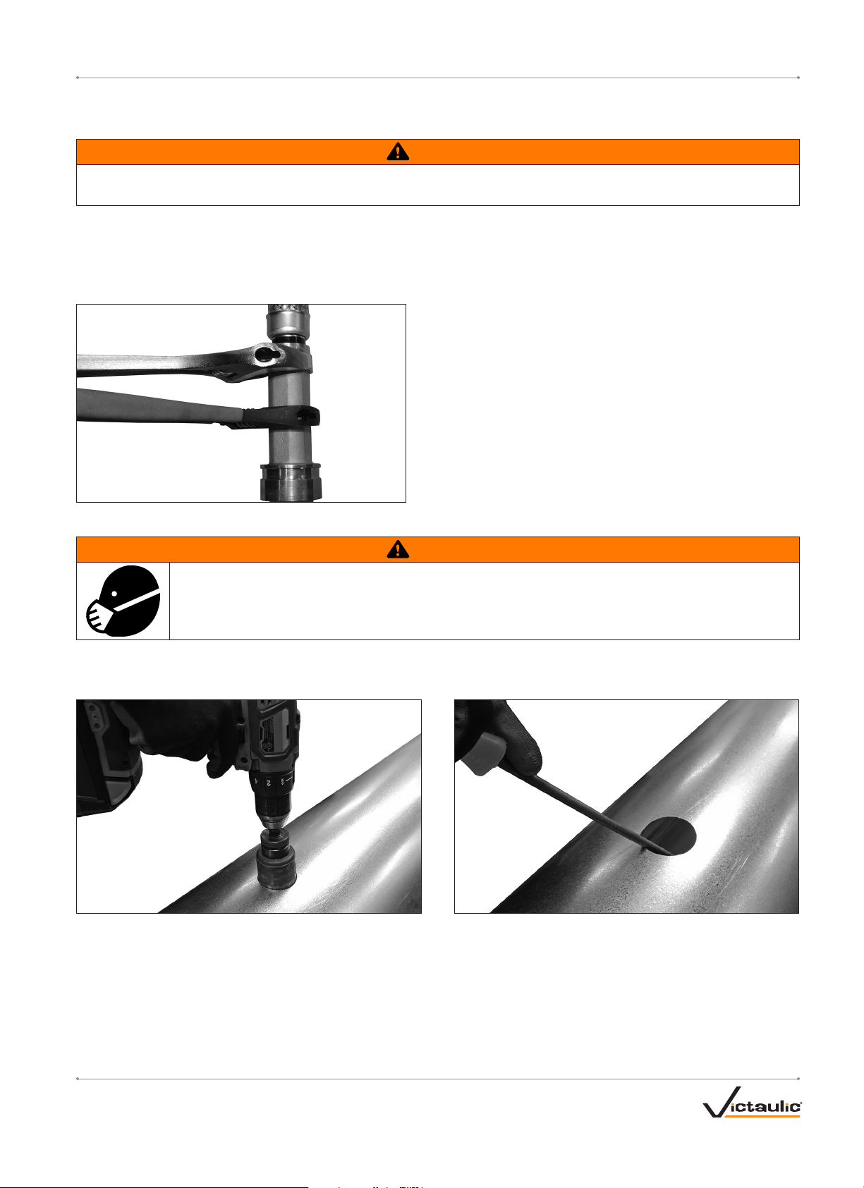
1. DO NOT DISASSEMBLE THE COUPLING: The Style 108 Coupling
of the Series AH2-CC is designed so that the installer does not
need to remove the nut, bolt, or linkage for initial installation. This
facilitates installation by allowing the installer to directly insert the
sprinkler piping’s grooved end into the coupling.
2. The outside surface of the sprinkler piping, between the groove
and the end of the sprinkler piping, shall be generally free from
indentations, projections, weld seam anomalies, and roll marks
to ensure a leak-tight seal. All oil, grease, loose paint, dirt, and
cutting particles shall be removed.
The sprinkler piping’s outside diameter (“OD”), groove dimensions,
and maximum allowable flare diameter shall be within the tolerances
published in current Victaulic IGS specifications, publication 25.14,
which can be downloaded at victaulic.com.
3. Check the gasket to verify that it is suitable for the intended
service. The color code identifies the material grade. Refer to
Victaulic publication 05.01 for the color code chart, which can
be downloaded at victaulic.com, and the “NOTICE” below for
important gasket information.
CAUTION
• If any conditions listed in the "NOTICE" below are met, a thin
coat of a compatible lubricant shall be applied only to the gasket
sealing lips to help prevent pinching, rolling, or tearing during
installation.
• DO NOT use excessive lubricant on the gasket sealing lips.
Failure to use a compatible lubricant may cause gasket damage,
resulting in joint leakage and property damage.
3a. If any conditions listed in the “NOTICE” below are met, apply a
thin coat of a compatible lubricant, such as Victaulic Lubricant
or an EPDM-compatible lubricant, only to the gasket sealing lips.
Silicone grease may be used (silicone spray is not a compatible
lubricant).
NOTICE
• Gaskets for Style 108 Coupling assemblies of AH2-CC Flexible
Hoses are pre-lubricated. Additional lubrication is not required
for the initial installation of wet pipe systems that are installed
at or continuously operating above 0°F/–18°C.
Supplemental lubrication is required only if any of the following
conditions exist. Apply a thin coat of a compatible lubricant to
the gasket sealing lips, as noted in step 3a on this page. It is
not necessary to remove the gasket from the housings to apply
additional lubricant to the gasket sealing lips.
• If the installation or continuous operating temperature is below
0°F/–18°C
• If the gasket has been exposed to fluids prior to installation
• If the surface of the gasket does not have a hazy appearance
• If the gasket is being installed into a dry pipe system
• If the system will be subjected to air tests prior to being filled
with water
• If the gasket was involved in a previous installation
Lubricated gaskets will not enhance sealing capabilities on
adverse sprinkler piping conditions. Sprinkler piping condition
and preparation shall conform to the requirements listed in these
product installation instructions.
WARNING
• Never leave a Style 108 Coupling of a Series AH2-CC partially
assembled on grooved sprinkler piping. ALWAYS TIGHTEN THE
HARDWARE IMMEDIATELY IN ACCORDANCE WITH THESE
INSTRUCTIONS. A partially assembled coupling poses a drop or
fall hazard during installation and a burst hazard during testing.
• Keep hands away from the grooved sprinkler piping and the
openings of the coupling when attempting to insert the grooved
sprinkler piping into the coupling.
• Keep hands away from coupling openings during tightening.
Failure to follow these instructions could result in death or serious
personal injury and property damage.

I-VICFLEX.AQD-M_5
REV_B
I-VICFLEX.AQD-M / Victaulic®VicFlex™Styles AQD-M Bracket / Installation Instructions
4. Assemble the joint by
inserting the grooved end of
the sprinkler piping into the
opening of the coupling. The
grooved sprinkler piping shall
be inserted into the coupling
until contact with the center
leg of the gasket occurs. A
visual check is required to
verify that the coupling keys
align with the groove in the
sprinkler piping and engage
with the spacer on the inlet
end of the flexible hose.
WARNING
• The nut shall be tightened until metal-to-metal contact occurs at
the bolt pads, as indicated in steps 5 and 6.
• DO NOT overtighten coupling hardware.
Failure to follow instructions for tightening hardware could result in:
• Personal injury or death
• Bolt damage or fracture
• Damaged or broken bolt pads or coupling fractures
• Joint leakage and property damage
• A negative impact on system integrity
GOOD
OVAL NECK OF BOLT
SEATED PROPERLY
BAD
OVAL NECK OF BOLT
NOT SEATED PROPERLY
5. Using an impact tool or a standard socket wrench with an
⁄-inch (for Imperial nut)/17-mm (for Metric nut) deep well
socket, tighten the nut until metal-to-metal contact occurs at the
bolt pads. Verify that the oval neck of the bolt seats properly in the
bolt hole. DO NOT continue to tighten the nut after metal-to-metal
bolt pad contact is achieved. If you suspect that any hardware
has been over-tightened (as indicated by a bend in the bolt,
bulging of the nut at the bolt pad interface, or damage to the
bolt pad, etc.), the entire coupling assembly shall be replaced
immediately. NOTE: During tightening, support the hose near the
Style 108 Coupling to verify that the inlet end of the Series AH2-CC
Flexible Hose remains straight and aligned with the coupling.
WARNING
• Visual inspection of each joint is required.
• Improperly assembled joints shall be corrected before the
system is tested or placed into service.
• Any components that exhibit physical damage due to improper
assembly shall be replaced before the system is tested or placed
into service.
Failure to follow these instructions could cause joint failure,
resulting in death or serious personal injury and property damage.
GOOD
BAD
6. Visually inspect the bolt pads at each joint to verify that metal-
to-metal contact is achieved, in accordance with step 5.
NOTICE
• Refer to the instructions on page 10 for reassembly
requirements.

I-VICFLEX.AQD-M_6 REV_B
I-VICFLEX.AQD-M / Victaulic®VicFlex™Style AQD-M Bracket / Installation Instructions
INSTRUCTIONS FOR INITIAL USE OF A VICTAULIC®FIRELOCK™NO. 101 90°ELBOW OR
NO. 102 STRAIGHT TEE INSTALLATION-READY™FITTING WITH A SERIES AH2-CC FLEXIBLE HOSE
(1-INCH/DN25 IGS CONNECTION)
NOTICE
• The following procedure applies only to 1-inch/DN25 No. 101 90° Elbows and No. 102 Straight Tees (IGS connection).
• No. 101 90° Elbows and No. 102 Straight Tees do not ship preassembled to the Series AH2-CC Flexible Hose.
• The No. 101 or No. 102 does not need to be fully disassembled for initial installation onto the inlet end of the Series AH2-CC Flexible
Hose.
1. Loosen the nut of the Style 108 Coupling. Remove the Style 108 Coupling from the end of the Series
AH2-CC Flexible Hose.
Spacer
Inspect
Inlet End
of Flexible Hose
2. Inspect the inlet end of the Series AH2-CC Flexible Hose to verify that there is no damage (dents, crushed
edges, etc.). A new, Victaulic-supplied Series AH2-CC or Flexible Hose shall be used if any damage is
present.
3. Verify that the spacer is oriented on the inlet end of the Series AH2-CC Flexible Hose, as shown to the left.
4. Loosen and remove the hardware from the side of the No. 101 90° Elbow or No. 102 Straight Tee that is intended to connect with the inlet of the
Series AH2-CC Flexible Hose.
NO. 101 NO. 102
5. Insert the inlet end of the Series AH2-CC Flexible Hose into the No.
101 90° Elbow or No. 102 Straight Tee. Verify that the gasket is seated
fully in the gasket pocket of each housing and that the housings' keys
engage with the spacer on the inlet end of the Series AH2-CC Flexible
Hose.
5a. Reinstall the two bolts and nuts that were removed in step 4.
NOTE: Verify that the oval neck of each bolt seats properly in the bolt
holes. DO NOT tighten the nuts completely. The bolt pads need to
be set at a gap for installation of the fitting. The nuts should be flush
with the top of each bolt to provide the proper gap. Use caution when
handling the fitting/hose assembly (the fitting may not be secured
completely to the inlet end of the Series AH2-CC Flexible Hose).
6. Follow the steps in the I-101/103 or I-102/104 installation instructions for the required tightening sequence. NOTE: During tightening, verify
that the inlet end of the Series AH2-CC Flexible Hose remains straight and aligned with the opening of the No. 101 90° Elbow or No. 102
Straight Tee. The I-101/103 or I-102/104 can be accessed and downloaded by scanning the applicable QR code below. In addition, these
instructions contain important reassembly instructions and shall be referenced any time a No. 101 90° Elbow or No. 102 Straight Tee is removed
from the sprinkler piping and reused.
SCAN QR CODE FOR ACCESS TO THE FULL I-101/103
INSTALLATION INSTRUCTIONS ON VICTAULIC.COM
SCAN QR CODE FOR ACCESS TO THE FULL I-102/104
INSTALLATION INSTRUCTIONS ON VICTAULIC.COM

I-VICFLEX.AQD-M_7
REV_B
I-VICFLEX.AQD-M / Victaulic®VicFlex™Styles AQD-M Bracket / Installation Instructions
CONNECTION TO THE SPRINKLER PIPING USING THE SUPPLIED NO. 140 MALE NPT OR BSPT
THREAD X GROOVE ADAPTER
WARNING
• The flexible hose shall not be bent or fluctuated up-and-down or side-to-side when pressurized.
Failure to follow this instruction could cause improper sprinkler operation, resulting in death or serious personal injury and property damage.
1. Apply pipe joint compound or PTFE thread sealant tape to the tapered threads of the No. 140 Male NPT or BSPT Thread x Groove Adapter, in
accordance with the pipe joint compound or tape manufacturer’s instructions. Using a pipe wrench, tighten the adapter into the sprinkler piping.
2. Follow all applicable instructions on pages 4 – 6 to make the 1-inch/DN25 IGS connection of the Series AH2-CC Flexible Hose.
INSTALLATION OF THE SPRINKLER REDUCER ONTO THE FLEXIBLE HOSE
1. Confirm that the seal inside the nut of the flexible hose is in place
and is free from damage prior to installation. Connect the nut to the
sprinkler reducer.
• DO NOT use pipe joint compound or PTFE thread sealant tape on the
fine threads. The seal inside the nut of the flexible hose provides the
leak-proof connection.
• Tighten the connection nut to a torque of 40ft-lbs/54 N•m
(approximately ½ to ¾ of a turn past hand-tight). NOTE: To prevent
damage to the seal, tighten the assembly by applying torque only to the
connection nut and DO NOT exceed the specified torque.
INSTALLING THE STYLE AQD-M BRACKET ONTO THE DUCT
WARNING
• Wear a particle mask and protective gloves during preparation of the duct.
• Wear safety glasses, hardhat, and foot protection.
Failure to follow these instructions could result in serious respiratory system illness or other personal injury.
NOTE: Before performing the following steps, determine the location on the duct where the Style AQD-M Bracket will be installed. The location shall
permit easy access to the Style AQD-M Bracket for inspection purposes. Wear a particle mask, safety glasses, hardhat, and foot protection during this
phase of installation.
1. Drill a 1 ½-inch/38-mm hole into the surface of the duct at the desired location.
1a. Remove all burrs from the hole.
1b. Remove all cutting particles from the surface of the duct.

I-VICFLEX.AQD-M_8 REV_B
I-VICFLEX.AQD-M / Victaulic®VicFlex™Style AQD-M Bracket / Installation Instructions
2. Apply duct mastic/sealant to the duct around the drilled hole as
shown in the picture to the left. Always refer to the duct mastic/sealant
manufacturer's instructions.
3. Place the bracket onto the duct. 3a. Verify that the bracket opening is aligned with the hole in the duct.
4. Using the bracket as a template, drill a 3/16" hole at each location.
4a. Install a 3/16" stainless steel, domed-head, sealing blind rivet (recommended) into each drilled hole. NOTE: Hardware is not included and shall
be stainless steel or a material suitable for the application.
4b. Four stainless steel #10 Type AB self-tapping metal screws can be used instead of rivets. When using self-tapping sheet metal screws, holes do
not have to be drilled into the duct. NOTE: Hardware is not included and shall be stainless steel or a material suitable for the application.
5. Using a rivet squeezer tool, install the four rivets.

I-VICFLEX.AQD-M_9
REV_B
I-VICFLEX.AQD-M / Victaulic®VicFlex™Styles AQD-M Bracket / Installation Instructions
SPRINKLER INSTALLATION
1. Install the sprinkler by following the manufacturer’s installation instructions. For Victaulic sprinklers, refer to the I-40 Victaulic®FireLock™
Automatic Sprinklers Installation and Maintenance Instructions.
2. Install the sprinkler bag and O-ring. NOTE: Two different bag materials (cellophane and polyethylene) are provided with the shipment. Choose the
bag material that is appropriate for system conditions. The polyethylene bag is larger than the cellophane bag.
3. Slide the Style 109 Coupling over the sprinkler bag and O-ring.
SCAN QR CODE FOR ACCESS
TO THE I-109 INSTALLATION
INSTRUCTIONS
SCAN QR CODE FOR ACCESS TO
THE STYLE 005 INSTALLATION
INSTRUCTIONS IN THE I-100
FIELD INSTALLATION HANDBOOK
4. Insert sprinkler/bag assembly into bracket opening. 5. Install the Style 109 FireLock™Installation-Ready™Rigid Coupling.
Refer to the current version of the I-109 installation instructions.
5a. For applications where a Style 005 FireLock™Rigid Coupling with
silicone gasket is required, refer to the current version of the I-100 Field
Installation Handbook for instructions. For silicone gaskets, use Victaulic
Lubricant or a silicone-compatible lubricant. DO NOT use silicone
lubricant on silicone gaskets.
6. Apply the duct mastic/sealant to cover over any gaps between the bracket and the duct. Always follow duct/mastic sealant manufacturer's
instructions for cure times.
SPRINKLER BAG INSPECTION/MAINTENANCE
WARNING
• Always depressurize and drain the
piping system before attempting to
install, remove, adjust, or maintain
any Victaulic products.
Failure to follow this instruction could
result in death or serious personal
injury and property damage.
1. Verify that the system is depressurized and drained completely.
2. Loosen the coupling and remove the sprinkler reducer with sprinkler/sprinkler bag.
3. Replace sprinkler bag. NOTE: Sprinkler bags shall be replaced periodically so that heavy deposits of
residue do not accumulate. Follow all NFPA and Authority Having Jurisdiction (AHJ) requirements for
bag and sprinkler maintenance.

I-VICFLEX.AQD-M_10 REV_B
I-VICFLEX.AQD-M / Victaulic®VicFlex™Style AQD-M Bracket / Installation Instructions
INSTRUCTIONS FOR REASSEMBLY OF A SERIES
AH2-CC FLEXIBLE HOSE
WARNING
• Always verify that the piping system has
been completely depressurized and drained
immediately prior to installation, removal,
adjustment, or maintenance of any Victaulic
products.
• Confirm that any equipment, branch lines, or sections of piping
that may have been isolated for/during testing or due to valve
closures/positioning are identified, depressurized, and drained
immediately prior to installation, removal, adjustment, or
maintenance of any Victaulic products.
Failure to follow this instruction could result in death or serious
personal injury and property damage.
1. Verify that the system is depressurized and drained completely
before attempting to remove a Series AH2-CC Flexible Hose from
the sprinkler piping.
2. While supporting the Style 108 Coupling, loosen the nut until
backed off no further than flush with the end of the bolt. Carefully
remove the flexible hose/coupling assembly from the sprinkler
piping.
3. Fully disassemble the Style 108 Coupling from the inlet end of the
Series AH2-CC Flexible Hose by removing the nut, bolt, gasket,
and linkage from the housings. Inspect all components for any
damage or wear. If any damage or wear is present, use a new
Victaulic-supplied coupling assembly.
4. Verify that the outside surface of the sprinkler piping, between the
groove and the end of the sprinkler piping, is generally free from
indentations, projections, weld seam anomalies, and roll marks
to ensure a leak-tight seal. All oil, grease, loose paint, dirt, and
cutting particles shall be removed.
The sprinkler piping’s outside diameter (“OD”), groove
dimensions, and maximum allowable flare diameter shall
be within the tolerances published in current Victaulic IGS
specifications, publication 25.14, which can be downloaded at
victaulic.com.
Spacer
Inspect
Inlet End
of Flexible Hose
5. Inspect the end of the Series AH2-CC Flexible Hose to verify that
there is no damage (dents, crushed edges, etc.). A new, Victaulic-
supplied Series AH2-CC Flexible Hose shall be used if any damage
is present.
6. Verify that the spacer is oriented on the inlet end of the Series
AH2-CC Flexible Hose, as shown above.
CAUTION
• A thin coat of a compatible lubricant shall be used to help
prevent the gasket from pinching, rolling, or tearing during
reassembly.
• DO NOT use excessive lubricant on the gasket sealing lips and
exterior.
Failure to use a compatible lubricant may cause gasket damage,
resulting in joint leakage and property damage.
7. Apply a thin coat of a compatible lubricant, such as Victaulic
Lubricant or an EPDM-compatible lubricant, to the gasket sealing
lips and exterior. Silicone grease may be used (silicone spray is not
a compatible lubricant). It is normal for the gasket to have a hazy
white appearance after it has been in service.
8. Place the lubricated gasket
onto the inlet end of the
flexible hose, then place the
Style 108 Coupling housings
over the gasket. Verify that
the gasket is seated fully
in the gasket pocket of
each housing and that the
housings' keys engage with
the spacer.
9. Install the linkage onto the
housings, as shown to the
left.
10. Install the bolt, and thread a
nut onto the bolt.
NOTE: Verify that the oval
neck of the bolt seats
properly in the bolt hole.
DO NOT tighten the nut
completely. The bolt pads
need to be set at a gap for
reinstallation of the coupling.
The nut should be flush with
the top of the bolt to provide
the proper gap.
11. Follow all steps on page 5.

I-VICFLEX.AQD-M_11
REV_B
I-VICFLEX.AQD-M / Victaulic®VicFlex™Styles AQD-M Bracket / Installation Instructions
TECHNICAL DATA FOR
FLEXIBLE HOSES
The following section provides friction loss
information for flexible hoses that can be used
with Style AQD-M Brackets.
WARNING
• It is the system designer’s responsibility to verify suitability of stainless steel flexible hose for use with the intended fluid media within the
piping system and external environment.
• The material specifier shall evaluate the effect of chemical composition, pH level, operating temperature, chloride level, oxygen level, and
flow rate on stainless steel components to confirm system life will be acceptable for the intended service.
Failure to follow these instructions could cause product failure, resulting in death or serious personal injury and property damage.
SERIES AH2-CC FLEXIBLE HOSE FRICTION LOSS DATA (FM)
Model
Length of Flexible Hose
inches/mm
Outlet Size
inches/Metric
Equivalent Length of 1-inch/DN25 Schedule 40 Pipe
feet/meters*
Maximum Number
of 90° Bends§
AH2-CC-48 48
1220
½
DN15
23.4 3
7.1
* 7-inch/178-mm minimum bend radius (tested with standard 5 ¾-inch/146-mm length straight reducer)
§ A higher number of bends may be permitted, provided the sum of degrees is equal to or less than the total maximum allowable degrees of bends
(e.g. Two 90° bends equal 180°. Three 90° bends equal 270°). The minimum bend radius and maximum number of 90° offset (bends), stated in these installation instructions,
refer to the final installed condition of the hose.
For friction loss data for elbows, refer to Victaulic publication 10.85.
When using a No. 101 90° Elbow or a No. 102 Straight Tee in place of a Style 108 Coupling on the end of a Series AH2-CC Flexible Hose, the friction loss data shown above
shall be added to the No. 101 or No. 102 friction loss data published in Victaulic publication 10.54.
NOTE: Differences in equivalent lengths are due to varying test methods, per FM 1637 standards. Refer to these standards for additional information regarding friction loss
test methods.

I-VICFLEX.AQD-MINSTALLATION INSTRUCTIONS
Victaulic®VicFlex™Sprinkler Fittings for Metal Duct Applications
Style AQD-M Bracket
For complete contact information, visit victaulic.com
I-VICFLEX.AQD-M 14906 REV B UPDATED 07/2020 Z000AQDM00
VICTAULIC AND VICFLEX ARE REGISTERED TRADEMARKS OR TRADEMARKS OF VICTAULIC COMPANY AND/OR ITS AFFILIATED ENTITIES
IN THE UNITED STATES AND/OR OTHER COUNTRIES. © 2020 VICTAULIC COMPANY. ALL RIGHTS RESERVED.
Table of contents
Other Victaulic Plumbing Product manuals
Popular Plumbing Product manuals by other brands

Lux Elements
Lux Elements TUB-PUMP Series Instructions for assembly

Oras
Oras Inspera 3030F Installation and maintenance guide

Bristan
Bristan Rio RO 1/2 C Fitting Instructions & Contents List

VIGO
VIGO VGO1009 manual

Presto
Presto NEO SENSOR installation guide

Hans Grohe
Hans Grohe Raindance E 300 1jet EcoSmart 26239 7 Series Instructions for use/assembly instructions

Mirabelle
Mirabelle MIRWSCVL800CP instructions

Toto
Toto TLP02309 Operation manual

Uponor
Uponor Q&E Fitting instructions

Hans Grohe
Hans Grohe AXOR Starck Nature 240 1 jet 12670 Series Assembly instructions

Axor
Axor Citterio 39850 Series Instructions for use/assembly instructions

KWC
KWC ZSHOW0014 Installation and operating instructions