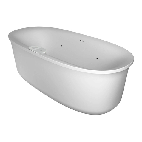
Victory Spa Aruba Manual

TECHNICAL INFORMATION
TECHNISCHE INFORMATIONEN
INFORMACJE TECHNICZNE
DE
PL
EN


INDEX
1. Disinfection...................................................................................................................................3
2. Building over of the tub..................................................................................................................4
3. Replacement of remote control batteries........................................................................................5
4. Replacement of the bulb of the underwater light ............................................................................5
5. Whirlpools power connection........................................................................................................7
6. Transport safety plug....................................................................................................................12
7. Cabins outside installation connection......................................................................................... 13
8. Steam circulation.........................................................................................................................17
9. Mauritius Maxoutside installation connection ...........................................................................18
10. Main conditions to be satisfied by an object where installation of a spa bath
is planned.................................................................................................................................19
11. Availability of the exclusive systems in individual models of the Victory Spa baths..................60
12. Water pump motor power...........................................................................................................61
13. Whirlpools power consumption.................................................................................................62
14. R 64
15. Extras.........................................................................................................................................65
16. Whirlpools outside installation connection................................................................................67
17. Whirlpools electric diagrams.....................................................................................................84
18.Cabins electric diagrams...........................................................................................................101
19.Spas electric diagrams..............................................................................................................101
ecessed back jets......................................................................................................................
1
INHALTSVERZEICHNIS
1. Desinfektionsprogramm..............................................................................................................22
2. Bebauung der Badewanne............................................................................................................23
3. Batterie im Fernbedienungsgerät ersetzen....................................................................................24
4. Wechsel der Glühbirne in der Unterwasserbeleuchtung...............................................................24
5. Anschluss zum Netzwerk.............................................................................................................26
6. Sicherheitsverschluss des Luftgebläses.......................................................................................31
7.Anschluss von Kabinen................................................................................................................32
8. Dampfzirkulation in Duschkabinen.............................................................................................36
9. Anschluss Mauritius MAX..........................................................................................................37
10. Objektbedingungen für die Installation einer SPA-Anlage........................................................38
11. Das Vorhandensein von exklusiven Systemen in den einzelnen Modellen der
Wannen Victory Spa........................................................................................................................60
12. Leistung des Pumpenmotors......................................................................................................61
13. Leistungsaufnahme der Wannen................................................................................................62
14. Umwälzungen unter Düsen........................................................................................................64
15. Zubehör......................................................................................................................................65
16. Anschluss der Außerinstallationen.............................................................................................67
17. Schema des elektrischenAnschluss - Wannen............................................................................84
18. Schema des elektrischenAnschluss - Duschkabinen ................................................................101
19. Schema des elektrischenAnschluss - SPA................................................................................114
EN
DE
Disinfecting agents for bathing water
The Victory Spa brand producer recommends application of the following agents to maintain a clean
bath:
- A liquid bactericide for baths with hydromassage - used in baths with automatic disinfection system
(OVS-06 to Tornado SMS systems). The agent is dosed directly into water before bathing. It is
absolutely nondetrimental for human health.
- A bactericide in quickly dissolving tablets for baths with hydromassage without automatic disinfection
(OVS-01 to OVS-04 systems). The agent has to be used before each bath. It is absolutely non-
detrimental for human health.
2. Carrying out disinfection.
a) With help of antibacterium liquid for whirlpools with automatic
disinfection systems available for OVS-06, OVS-GI and OVS-GII, Sirocco,
Typhoon, Tornado, Tornado SMS systems only.
Choose of disinfection type
There are two basic type of disinfection: disinfection before the bath and disinfection after the bath.
The type of disinfection has to be choosed before filling the whirlpool in.
If we assume, that we we will use option “disinfection before bath”, then after the bath we can still use
the other option.
Disinfection before bath
After establishing the type of disinfection , and filling the bath in with water, in the moment when the
green diode is switched on the touch panel, the antibacterium agent will be automatically dosed into
water, and the blower automatiacally will start to work for about 30 second. When devices switch off, it
is possible to have a bath. That is completely safe for human health.
The green diode on the disinfection button flickers when is not enough disinfection liquid in the
chemical container.
Attention: In case of that after filling in the bath will not be bactericide in chemical container,
disinfection program will be stopped till the moment the liquid will be completed. If we don't have
enough bactricide to filling up the level of the liquid in the container, we could cancel disinfection by
pressing disinfection button for about 5 second.
Disinfection after bath
After establishing the type of disinfection should be pressed disinfection button. Into bathtubs will be
dosed disinfection agent. The pump and the blower will start to work sequential. When devices switch
off (after about 10 minutes) the bath should be emtied.
Water disinfection will be made when bacticide is in the chemical container. When there is to little
disinfection liquid in the container the green diode on the disinfection button flickers. Besides on the
screen will be shown inscription “E3”, and no function of hydromassage will be anable. The disinfection
liquid should be refilled.
b) With help of quickly dissolving antibacterial tablets for whirlpools whithout automatic disinfection
systems from system OVS-01 to OVS-04 only.
Before every bath should put into the water one tablet for one person. Then switch on hydromassage
devices for about 20 sec. After this time it is possible to have a bath.
3
ENGLISH

Building over of the tub.
The building-in structure has to guarantee the easy access to the whirlpool components in case of after
sales service and also the proper ventilation of the space under the bath. The manufacturer guarantees
the fulfillment of the above conditions by proposing two types of solutions:
?with the acrylic masking panel - possible to remove - installation of the panel is done by its
placement behind the top edge of the tub.
The advantage of acrylic panel is easy access to the massage appliances which are under the tub.
The tub should be leveled in such a way that the gap between the panel and the floor of the room is
min 2 cm. This way the constant flow of air is provided and the massage appliances are ventilated.
?using the suggested "HydroPanel" construction. See details in a separate instruction.
Installation of the front panel
?fit small pressing-down springs as presented on the figure below,
?place the top edge of a panel under the top rim of the tub.
Note! The covering panel for Barbados baths has feet. In order to install the panel:
?slide the upper edge of the panel under the bath top,
?regulate the height of the panel feet.
In other cases of special form of building over, the following should be considered:
?ventilation of the area under the tub,
?free access to massage system devices (nozzles, pipes, air pump, water pump) the tub shall be taken
out from a tub enclosure or have an inspection opening.
4
ENGLISH

Replacement of remote control batteries
A remote control is equipped with a 3V battery marked with the CR2032
symbol.
In order to replace the battery:
1. Remove covers from the rear part of the remote control casing.
2. Remove screws connecting remote control casing (the photo illustrates
the view of disassembled remote control).
3. Replace the battery
4. Place both parts of remote control casing together and connect them
with the screws.
5. Put on the covers of the rear part of the remote control casing.
Note! Pay attention to the appropriate arrangement of the seal in
order to maintain the remote control watertight.
The replacement of the bulb of the underwater light.
The underwater light is equipped with the bulb 35 W 12 V. In order to replace the bulb you should:
1. disconnect the tub from power
2. unscrew the safety pin from the plate
3. unscrew the plate
4. remove the glass of the lamp
5. take out o-ring
6. change the bulb
7. check if o-ring is placed properly
8. put on the glass
9. screw the plate
10. screw the safety pin
11. connect the tub to the power
Battery Cr2032
cover plate
o-ring
glass
light bulb
locking pin
5
ENGLISH

Replacement of a bulb in an underwater lighting lamp colour.
Note! Bulb replacement should be realised from the inside of the bath.
Underwater lighting lamp is equipped with a halogen bulb 35 W 12V with MR 11 symbol, lamp cap GU4.
In order to replace the lamp bulb:
?make sure that location of a fastening disc allows for accessing the bulb, i.e. whether a colour glass
does not cover the bulb. If the colour glass covers the bulb, switch on the underwater lighting and
draw the fastening disc using a switch of colour change to a position where the bulb is not covered.
?disconnect bath power supply,
?unscrew a cover plate,
?unscrew 6 screws fastening the ring,
?remove the ring, glass and sealing rings,
?unscrew a screw plug using the supplied spanner,
?remove the bulb using a suction cup and replace it,
?screw the screw plug down using the supplied spanner,
?put on sealing rings and a glass check the correctness of the sealing rings arrangement,
?screw the ring down,
?screw the cover plate down,
?connect bath power supply.
suction cup
(for bulb removal)
spanner for unscrewing
(screwing down) screw plug
cover plate
screw
ring
glass bulb
screw plug
sealing rings
fastening disc
colour glass
6
ENGLISH

POWER CONNECTION
Power connection of a bath must be carried out by an installation
company certified by TECHNIC INDUSTRY. Connection of electric
installation into a bath must be carried out in accordance with the
EN-60335-1 standard. It must be carried out permanently i.e. it is
forbidden to finish a bath power lead with a plug and then plug in into a
socket!
Attention! A bath is equipped with power leads of the following colours:
a) 1 phase connection:
phase wire L : brown
zero lead N : blue
safety lead : yellow-green.
b) multi-phase connection:
phase wires L : black or brown – with proper numbers
zero lead N : blue
safety lead : yellow-green.
Attention! Bath aluminium frame must be grounded. Clamps of a
grounding lead and a compensating lead are clearly indicated on
aluminium frame.
7
ENGLISH

The following table includes recommended by TECHNIC INDUSTRY
method of connecting a bathe into electric installation depending on
hydromassage system (and in specific cases – bath model) as well as required
overcurrent protection resulting from power input.
ATTENTION: All devices constituting hydromassage system are one phased
powered with ~230 V; 50 Hz current.
SYSTEM MAXIMUM
POWER CONNECTION
METHOD
POWER LEAD
in electric
installation
OVERCURRENT
PROTECTION
OVS-01 (A,B) 1000 W 1 PHASE B 16 2
3 x 2,5 mm
OVS-01 (A,B)
LANZAROTE, SINGAPORE 2000 W 1 PHASE B 16 2
3 x 2,5 mm
OVS-02 (A)
3800 W
1 PHASE B 16 2
3 x 2,5 mm
OVS-02 (A) WITH A
HEATER 2700W
OVS-02 (A)
LANZAROTE, SINGAPORE
OVS-02 (A) WITH A
HEATER 2700W
LANZAROTE, SINGAPORE
OVS-03 (A)
OVS-03 (A) WITH A
HEATER 2700W
OVS-03 (A)
LANZAROTE, SINGAPORE
OVS-03 (A) WITH A
HEATER 2700W
LANZAROTE, SINGAPORE
2200 W
1100 W
4900 W
2100 W
4800 W
4200 W
6900 W
2 PHASES
1 PHASE
1 PHASE
2 PHASES
1 PHASE
1 PHASE
2 PHASES
1 PHASE
2 PHASES
1 PHASE
3 PHASES
B16 / phase
B 25
B 16
B16 / phase
B 25
B 16
B16 / phase
B 25
B16 / phase
B 25
B16 / phase
2
4 x 2,5 mm
2
3 x 4 mm
2
3 x 2,5 mm
2
4 x 2,5 mm
2
3 x 4 mm
2
3 x 2,5 mm
2
4 x 2,5 mm
2
3 x 4 mm
2
4 x 2,5 mm
2
3 x 4 mm
2
5 x 2,5 mm
ELECTRIC INSTALLATION PROTECTION AND A BATH
CONNECTING METHOD
8
ENGLISH

9
ENGLISH
OVS-04 (A)
LANZAROTE, SINGAPORE
B 25 2
3 x 4 mm
OVS-04 (A) WITH A
HEATER 2700W
LANZAROTE, SINGAPORE
4200 W B 25
2
4 x 2,5 mm
2
3 x 4 mm
3 PHASES 2
5 x 2,5 mm
6900 W
OVS-06 (CHROMO) B 16 2
3 x 2,5 mm
2100 W
4800 W
2
4 x 2,5 mm
2
3 x 4 mm
OVS-06 (CHROMO) WITH A
HEATER 2700W B 25
OVS-06 (CHROMO)
LANZAROTE, SINGAPORE 4200 W B 25
2
4 x 2,5 mm
2
3 x 4 mm
OVS-06 (CHROMO) WITH A
HEATER 2700W
LANZAROTE, SINGAPORE
2
5 x 2,5 mm
6900 W
OVS-GI (CHROMO) C 16 2
3 x 2,5 mm
2100 W
4200 W
2
4 x 2,5 mm
2
3 x 4 mmC 25
OVS-GI (CHROMO)
LANZAROTE, SINGAPORE
4800 W C 25
2
4 x 2,5 mm
2
3 x 4 mm
2
5 x 2,5 mm
6900 W
OVS-GII (CHROMO)
4800 W
OVS-GII (CHROMO)
LANZAROTE, SINGAPORE
SIROCCO
6900 W
SIROCCO
LANZAROTE, SINGAPORE
2
5 x 2,5 mm
5800 W
TYPHOON
2
5 x 2,5 mm
6900 W
TYPHOON
LANZAROTE, SINGAPORE
2
5 x 2,5 mm
5800 W
TORNADO
2
5 x 2,5 mm
6900 W
TORNADO
LANZAROTE, SINGAPORE
OVS-04 (A)
1 PHASE
B 16 2
3 x 2,5 mm
4800 W
2 PHASES
2
4 x 2,5 mm
2100 W
OVS-04 (A) WITH A
HEATER 2700W
2
5 x 2,5 mm
2
5 x 2,5 mm
C16 / PHASE
B16 / PHASE
2
4 x 2,5 mm
2
4 x 2,5 mm
2
4 x 2,5 mm
2
3 x 4 mm
L1+L2 / B16
L3 / B16
L1+L3 / B20
L2 / B16
L1+L3 / C20
L2 / C16
B 25
SYSTEM MAXIMUM
POWER CONNECTION
METHOD
POWER LEAD
in electric
installation
OVERCURRENT
PROTECTION
B16 / PHASE
B16 / PHASE
B16 / PHASE
B16 / PHASE
B16 / PHASE
C16 / PHASE
B16 / PHASE
B16 / PHASE
B16 / PHASE
C16 / PHASE
1 PHASE
1 PHASE
1 PHASE
1 PHASE
1 PHASE
1 PHASE
1 PHASE
1 PHASE
1 PHASE
2 PHASES
2 PHASES
2 PHASES
2 PHASES
2 PHASES
2 PHASES
2 PHASES
2 PHASES
3 PHASES
3 PHASES
3 PHASES
3 PHASES
3 PHASES
3 PHASES
3 PHASES
B16 / PHASE
C16 / PHASE
C16 / PHASE
C16 / PHASE
3 PHASES

DENOTATIONS:
OVS – system symbol
0x – system number
A, B, CHROMO – system variant
where:
A – underwater lighting system
B – air massage system with efficiency regulation
CHROMO – chromotherapy system
A bath as a device of substantial power – frequently exceeding 2kW – must by
powered from a separate, independent circuit, protected with an vercurrent switch
according to the table
of pole number equal = number of phases + N
All baths must be connected with use of a differential switch of In=0,03A.
It can be realised as overcurrent switch with differential module.
Power supply from 2 or accordingly 3 phases is preferable in all systems where it is possible (c.f. table)
– they can be also connected into existing one-phase installations ( but this is not recommended by
producer TECHNIC INDUSTRY, due to too high power ) – by connecting phase wires of bath
power lead with phase wire of power lead – accordingly higher overcurrent protection must be
applied.
10
ENGLISH
2
5 x 2,5 mm
6900 W
TORNADO SMS
LANZAROTE, SINGAPORE
2
5 x 2,5 mm
9100 W
TORNADO SMS WITH A
HEATER 6000W
2
5 x 2,5 mm
10200 W
TORNADO SMSWITH A
HEATER 6000W
LANZAROTE, SINGAPORE C25 / PHASE
3 PHASES 2
5 x 2,5 mm
5800 W
TORNADO SMS C16 / PHASE
2 PHASES 2
4 x 2,5 mm
L1+L3 / C20
L2 / C16
SYSTEM MAXIMUM
POWER CONNECTION
METHOD
POWER LEAD
in electric
installation
OVERCURRENT
PROTECTION
C16 / PHASE
C16 / PHASE
3 PHASES
3 PHASES
3 PHASES

CONNECTION METHOD:
11
ENGLISH
3
2
3x2,5mm2
3x1,5mm
N
L
PE
PE L N
3
2
3x2,5mm
L-N 230 VAC
5
2
5x2,5mm
N
L1
L2
L3
PE
5
2
5x2,5mm L1-N 230 VAC
PE L3 L2 L1 N
L2-N 230 VAC
L3-N 230 VAC
4
2
4x2,5mm
N
L1
L2
PE
4
2
4x2,5mm L1-N 230 VAC
PE L2 L1 N
L2-N 230 VAC
3
2
3x4mm
PE L N
L-N 230 VAC
4
2
4x2,5mm
N
L1
L2
PE
3 PHASES to 2 PHASES
(Systems: Sirocco, OVS-02 with a heater 2700W
(Lanzarote, Singapore)).
3 PHASES to 2 PHASES
(Systems: Typhoon, Tornado, Tornado SMS;
OVS: 03, 04, 06, GI (Lanzarote, Singapore))
5
2
5x2,5mm
N
L1
L3
L2
PE
4
2
4x2,5mm L1-N 230 VAC
PE L2 L1 N
L2-N 230 VAC
5
2
5x2,5mm
N
L1
L2
L3
PE
4
2
4x2,5mm L1-N 230 VAC
PE L2 L1 N
L2-N 230 VAC
3 PHASES:1 PHASE:
2 PHASES to 1 PHASE:2 PHASES:
OVERCURRENT SWITCH
WITH DIFFERENTIAL MODULE
B 16/0.03A
DIFFERENTIAL SWITCH OF
In=0,03A
OVERCURRENT SWITCH
[C.F. TABLE]
DIFFERENTIAL SWITCH OF
In=0,03A
OVERCURRENT SWITCH
[C.F. TABLE]
DIFFERENTIAL SWITCH OF
In=0,03A
OVERCURRENT SWITCHES
[C.F. TABLE]
OVERCURRENT SWITCH
WITH DIFFERENTIAL MODULE B
[C.F. TABLE] / 0.03 A

To eliminate water inlet to air blower during transport time, we have decided
to put on an additive screw connection on the pipes supplying air (see fig.1).
During transport time system stays disconnected.
After whirlpool is unpacked, Customer must take fallowing steps
(just at the first time starting):
1. 2. 3.
1. Take off safety plug
2. Put connection nut in suitable place
3. Screw together both parts of connection
Fig 1. Location.
Fig 2. Steps to make.
AIR BLOWER
CONNECTION
12
ENGLISH

Outside installation connection.
A. Water supply system connection.
- Cabin is equipped with valves cutting off water and filters located on shower base frame.After cabin installation,
connect filter outputs and thermostatic battery output using supplied hoses.
- Connect hoses supplying hot and cold portable water to valve terminals (1/2½) according to markings on filters:
ORed - hot water
OBlue - cold water
Draw supply hoses here
Connect filter outputs
with thermostatic battery
inputs
Connection of water supply filters (Orinoco, Mississipi)
Connection of water supply filters (Amazon)
Connection of water supply filters (Galapagos)
b. Sewage system connection.
Realise sewage system connection in a standard way f50 mm connection.
Draw supply hoses here
Connect filter outputs
with thermostatic battery
inputs
Draw supply hoses here
Connect filter outputs
with thermostatic battery
inputs
13
ENGLISH

c. Connection of electric system earth conductors.
Connect earth conductor terminals on a shower base frame in a clearly indicated place:
- Control box earth
- Battery earth
- Steam generator frame earth.
NOTE! Aluminium cabin frame needs to be grounded.
d. Ventilation system connection.
Ventilation grating (or gratings) placed in the top of the cabin connects with air duct shown beneath on the
photo.
e. Electric system connection.
Electric system connection needs to be realised according to EN-60335-1 standard. It should be realised in a
permanent way, i.e. end of power supply cable cannot end as a plug and then be connected to socket.
A)Amazon, Mississipi, Orinoco, Cassiopeia
The following type of equipment needs to be used in this installation:
- 16Afuse (Mississipi), 20Afuse (Orinoco,Amazon, Cassiopeia)
- two - polar switch
2
- 3x2,5 mm power supply cable
- electric switch-gear protected with various-current switch of In0,03A.
Note! Cabin is equipped with a power supply cable of the following colours:
- L phase cable : brown
- N zero cable : blue
- protecting cable : yellow-green.
b) Galapagos
Attention!Acabin is equipped with power leads of the following colours:
a) 1 phase connection:
phase wire L : brown
zero lead N : blue
safety lead : yellow-green.
b) multi-phase connection:
phase wires L : black or brown with proper numbers
zero lead N : blue
Safety lead : yellow-green.
Elastic sewer f100mm
The outlet of
the air duct
The air duct
On the air duct's outlet should be put the sewer with diameter f100mm like on the photo below. Connection should
be secured with a clamp. The sewer should be connected to domestic ventilation system.
14
ENGLISH

ATTENTION: All devices constituting hydromassage system are one-phased powered with ~230 V; 50 Hz
current.
Overcurrent switch B16
of pole number equal = number of phases + N
Cabin must be connected with use of a differential switch of In=0,03A.
It can be realised as overcurrent switch with differential module.
Power supply from 2 or accordingly 3 phases is preferable it can be also connected into existing one-phase
installations ( but this is not recommended by producer TECHNIC INDUSTRY, due to too high power )
by connecting phase wires of bath power lead with phase wire of power lead accordingly higher overcurrent
protection must be applied.
WARIANT MAXIMUM
POWER OVERCURRENT
PROTECTION
POWER LEAD
in electric
installation
1
2
3
4
1 Phase
3 Phases
3 Phases
3 Phases
B16
B16 / Phase
C16 / Phase
C16 / Phase
2
3x2,5 mm
2
5x2,5 mm
2
5x2,5 mm
2
5x2,5 mm
15
ENGLISH
CONNECTION
METHOD
2135 W
7950 W
9405 W
9415 W
Cabins power consumption
CABIN MAXIMUM
POWER
ORINOCO
MISSISSIPI
AMAZON
CASSIOPEIA
3500 W
2700 W
3500 W
3500 W
Galapagos power consumption

16
ENGLISH
0~60400
100~150
200~ 00
3
12
3
0~30
20 0
1 HOT WATER TERMINAL
2 COLD WATER TERMINAL
3 SEWAGE SYSTEM OUTLET
Supply cable should be attached at the corner
Connection of Mississipi cabin.
60 ~
0800
100~150
200~300
12
3
200~300
1 HOT WATER TERMINAL
2 COLD WATER TERMINAL
3 SEWAGE SYSTEM OUTLET
Supply cable should be attached at the corner
Connection of Orinoco cabin.
3
2
1
100÷150mm
100÷150mm
min 1500mm
100mm
1 HOT WATER TERMINAL
2 COLD WATER TERMINAL
3 SEWAGE SYSTEM OUTLET
Supply cable should be attached at the corner
Connection of Amazon cabin.
1 HOT WATER TERMINAL
2 COLD WATER TERMINAL
3 SEWAGE SYSTEM OUTLET
Supply cable should be attached at the corner
Connection of Galapagos cabin.

17
ENGLISH
Steam circulation in cabins
This revolutionary steam circulation solution guarantees equal steam distribution, effectively filling the whole of
the cabin. Closed circulation guarantees that the cabin is completely filled with steam in an incomparably short
time. Just the air from the cabin is circulating so no cool air is extracted from outside your wellness capsule.
The differences in temperature between upper and lower parts of the cabin are so minimal you cannot feel it.
No more cold spots!
Cycle with closed steam circulation
Fan
Steam generator
Steam
Steam
Steam
Suction
Suction
1 ELECTRIC CONNECTION
2 HOT WATER TERMINAL
3 COLD WATER TERMINAL
4 SEWAGE SYSTEM OUTLET
Connection of Cassiopeia Variant I
1 ELECTRIC CONNECTION
2 HOT WATER TERMINAL
3 COLD WATER TERMINAL
4 SEWAGE SYSTEM OUTLET
Connection of Cassiopeia Variant II
1700÷1800
200÷250
1
2
3
4
1700÷1800
200÷250
1
2
3
4
20~3
0 00
00~
2 300
a n zze
Ste m o l

18
ENGLISH
Outside installation connection - Mauritius MAX.
A. Water supply system connection.
Draw supply hoses here
Connection of water supply filters
b. Sewage system connection.
Realise sewage system connection in a standard way f50 mm connection.
1550
330~450
100~600
12
3
850~ 301 0
1 HOT WATER TERMINAL
2 COLD WATER TERMINAL
3 SEWAGE SYSTEM OUTLET
Supply cable should be attached at the corner
Connection of Mauritius Max 165 left .
1550
330~450
100~600
1
23
850~1300
1 HOT WATER TERMINAL
2 COLD WATER TERMINAL
3 SEWAGE SYSTEM OUTLET
Supply cable should be attached at the corner
Connection of Mauritius Max 165 right .
1650
330~450
100~600
12
3
850~ 30
1 0
1 HOT WATER TERMINAL
2 COLD WATER TERMINAL
3 SEWAGE SYSTEM OUTLET
Supply cable should be attached at the corner
Connection of Mauritius Max 175 left .
1560
330~450
100~600
1
23
85 ~1300
0
1 HOT WATER TERMINAL
2 COLD WATER TERMINAL
3 SEWAGE SYSTEM OUTLET
Supply cable should be attached at the corner
Connection of Mauritius Max 175 right .

Requirements concerning a bathing room:
1. Adequate dimensions and height.
2. Transport holes for carrying the bath in.
3. Facility for draining water from the floor on which the bath is to be founded.
4. Facility for steam removing.
While selecting a room the following criteria should be considered:
• a bathing room must not be too small. The minimum area should be three times as large
as the area of a selected bath type with the shape approximated to a rectangular; thus it will
be possible to build a casing and enough room will be left around the bath. That minimum
area may be chosen only if is possible to build the bath in the floor.
• if the bath cannot be sunk in the floor, the room must be higher and larger (total height of
a bath on a supporting structure is about 1m) to provide easy access to the bath and make it
possible to walk around in an unbent position. In that case the recommended minimum
height is about 3 m, and the recommended minimum area is 5 times larger than the bath
area approximated to a rectangular.
Minimum dimensions of transport holes result from engineering drawings of bath
models. A rectangular hole should have the following dimensions:
• A dimension: height of the bath with its rack
• B dimension: shorter of two linear dimensions (length or width) plus 10 cm
Since there is a risk of flooding the floor on which the bath is installed, the floor must
be provided with a floor drain connected with the sewage system of the building. If the
sewage plumb-line is situated above the floor, a gully of dimensions of 50 x 50 x 50 cm must
3
be constructed and a pump of capacity of at least 8 m /h (provided with a floating sensor and
connected with the sewage system) should be installed.
o
A multi-person SPA bath is an relaxing object with water of temperature of 35-40 C. Due to
that a large quantity of steam is emitted in the bathing room. To reduce evaporation the room
o
temperature must be about 24-25 C and a mechanical pressure and exhaust ventilation system
o
should be installed. If the bath is not used, the water temperature should be 25 C. The air
relative humidity should be 60-70 %. If it is not possible, a steam condenser should be
installed to keep constant air humidity, reduce the risk of damage of walls and the ceiling
resulting from excessive air humidity. If the building is air-conditioned the steam condenser
need not be installed.
MAIN CONDITIONS TO BE SATISFIED BY AN OBJECT WHERE
INSTALLATION OF A SPA BATH IS PLANNED
19
ENGLISH
This manual suits for next models
38
Table of contents
Other Victory Spa Hot Tub manuals
Popular Hot Tub manuals by other brands

HANSCRAFT
HANSCRAFT SPATOUCH 3 user manual

HotSpring
HotSpring Limelight owner's manual

Aquatic
Aquatic AI31LUX6636ISL Specifications

Bestway
Bestway LAY-Z-SPA MIAMI AIRJET S100102 owner's manual

Aries Acrylic
Aries Acrylic Aries Spas owner's manual

Jacuzzi
Jacuzzi J-200 Series Instructions for preinstallation