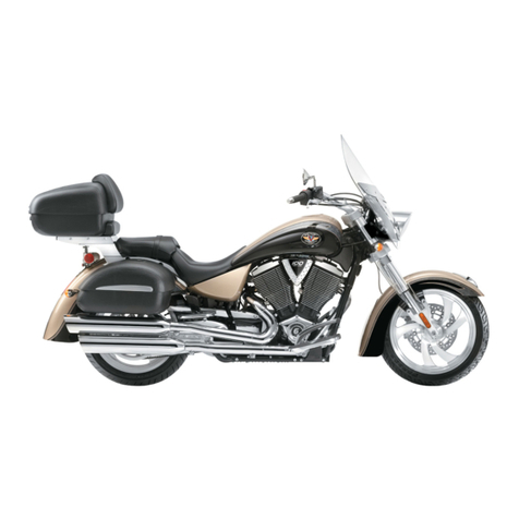
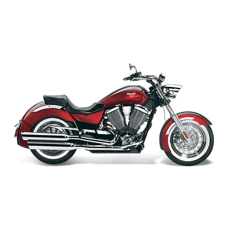
Victory KINGPIN 2006 User manual

VICTORY KINGPIN (06-up)
Place bike on center stand support
Remove side covers, chrome fender strut covers
Remove rear seat and front seat
Remove mufflers, rear headpipe, and muffler bracket. Unplug o2 sensor if equipped.
Unplug and remove fender. Cut plug from fender; be sure to leave enough wire to splice
in our pigtail adapter. (Fender will be trimmed and re-installed)
Remove plastic cover at back of frame near engine (remove control box from plastic
cover and secure to PCM
Remove caliper from rear wheel (do NOT disconnect brake line at this time to prevent
fluid loss)
Loosen belt adjusters and remove rear axle. Remove rear wheel, caliper brackets, etc.
Unfasten fuse box from the mounting bracket to access the rear shock mount just behind
the rear brake reservoir. Remove upper shock mounting bolt
Remove “dog bones” from the swing arm and motorcycle frame.
Remove front swing arm retaining nut and pull swing arm from left side of the bike.
Remove swing arm and shock as one unit.
Remove 2 upper engine mounting bolts at back of motor. Drill the rearmost frame horns
to 5/16”. Cut the exhaust mounting stud from swing arm shaft. The exhaust bracket
attached to frame will remain in place. Trim fender so that it will clear our trike frame.
Cut the back side just forward of the tag bracket. You will have to notch the rearmost
mounting holes for our trike frame. (The front side of the fender does not have to be cut.
BUILD PROCEDURE
Remove swing arm, 3rd, and 4th link from rear end. Remove wheels from rear end. Stand
rear end on its “end” and remove the 5/16” bolts and spacers from around pulley and
disconnect brake line at pulley. Install new bearings into swing arm. Use 2 bearings on
each side, install bearing sleeve. Apply grease to inside edge of swing arm to prevent any
noise as swing arm travels and rubs against frame. Install swing arm and tighten. Set

heim joints to 2 full turns out. (The tab for the 3rd and 4th link will be on the bottom side
of swing arm.
Place fender on bike and install trike frame. The front tabs of frame will mount with the
stock bolts at the rear engine mount (Be sure to use lock-tite 242 blue). Start bolts and
swing frame up and bolt in place. Once all bolts are started, fully tighten.
Slide rear end under frame and route belt around pulley. Start all 5/16” bolts with spacers
previously removed. Do not tighten yet. Attach swing arm to rear end (swing arm
mounts in the second hole from the TOP of rear end and the full length spacer with ½”
bolts goes on the bottom of the rear end). Tighten all bolts around pulley and attach
brake line at pulley. Attach 3rd link bar to rear end and to swing arm (leave 4th link off at
this time). Using a floor jack, lift the rear end and attach shocks using lock-tite 242
(blue). The offset on the shock goes on the bottom and faces the back of the motorcycle.
Install air bags, air line, and T fitting. Pressurize air bags (approx 60 psi) and use a soapy
water mix to spray on all fittings to check for leaks. Spin rear end to ensure belt is
properly tracking. Remove air from bags and compress suspension using jack. Install
rear head pipe and tighten. (If equipped with o2 sensor, plug in.) Using the extensions
provided in kit, route mufflers to the back of the trike. Using the stock muffler mounting
“strap”. Position mufflers and attach strap to mufflers and mark point to cut strap (must
be shortened for clearance). Using the supplied metal spacers and bracket to mount the
mufflers to trike frame (you will have to drill a hole in the “strap” for mounting the
bracket), mark location to drill a 5/16” hole through frame and mount bracket (no rubber
bushing is needed as the motor is a structural part of the frame and the exhaust does not
move as with a typical rubber mounted motor/exhaust assembly). Tighten all exhaust
clamps, start bike and check for exhaust leaks.
Remove the stock brake caliper and attach to the aluminum brake block included in our
kit with the banjo bolt and crush washers provided. Attach the brake line on rear end to
the elbow on the brake block (be sure to use Teflon tape on elbow where it threads into
brake block. Adjust brakes for proper drag (approx 1/3 of a revolution). Bleed the brakes
and check for leaks. Attach brake block to rear end using the supplied ¼” bolt and
nylock. Secure the factory brake line to the swing arm to prevent damage.
WIRING
Victory uses an LED lighting system for the tail light and brake light; because of this
there is only partial voltage at the plug going to the rear fender. (When brakes are applied
there is not sufficient voltage to properly activate the brake lights). You must tap into the
brake light switch at the back of the motorcycle frame and route wire to the universal
pigtail in kit. Using the factory plug removed from fender, splice to the universal pigtail
in our kit. You will need a test light or similar to test the factory wires for function as the
color combinations vary by year. The color codes for our harness is as follows. (Note
that the brake wire on our harness will connect to the brake light switch at the back of
motorcycle as previously stated). The use of a load equalizer is not needed on the
Victory kit.

UNIVERSAL HARNESS
Green –Ground
Black –Running
Yellow –Stop
Blue –Right turn
Orange –Left turn
Once the sub harness is connected to the factory system, attach our wiring harness and
route to the back of the motorcycle. The wire with the red tape and the 2 wires coming
out at the back of harness indicates the right side of motorcycle. Secure the harness to the
frame to prevent damage caused by any moving parts.
Place wheels on trike and secure using 2 or 3 lug nuts. Remove center stand from bike
and set on jack stands (under axles). Using 3rd link bar, adjust belt tension to approx ½”
@ 10lbs pressure. When proper tension is set, install 4th link bar and tighten all mounting
points. Lock down all heim joints. The swing arm heim joints do not need lock-tite as
the nordlocks prevent jam nuts from backing off. All other heim joints need lock-tite 242
(blue) when being tightened to prevent backing off.
Install fender brackets leave enough slack in bolt to be able to slide bracket to fit properly
to body. Extend the trunk light wires before placing body on the trike. Place body onto
trike and support front fenders with jack stands. Place chrome struts on bike and bolt in
place as well as side covers. Body should rest just under chrome covers and fit side cover
lines as well. Wheels should be centered in the wheel well and the body should be even
across the back as well (height and side to side). If needed use washers to shim one side
of the body to achieve proper height. Double check all areas of body fitment before
drilling the back of body. Drill a hole to extend the license plate wires out the bottom of
the trunk and to the tie in point for the trunk light and license plate light to our harness.
(Be sure to seal the hole once you run wires out bottom of trunk). You will have to
remove the inner muffler to drill body. To ease the fitment and drilling for the fender
brackets, remove wheels to access. Fender brackets should fit snug against body, drill
using brackets to guide your bit and using the hardware board supplied, attach front of
body to brackets. Fully tighten fender brackets to frame.
Included in our kit is 2 fiberglass panel covers that help conceal the open area left
exposed on the victory motorcycle. There are 2 brackets in the kit that attach these
covers on the front side of the motorcycle near the engine. One bracket attaches to the
bolt directly underneath the brake reservoir. The bracket on the other side attaches to the

lower mounting point for the solenoid on the side of the battery box. The back side of the
covers provided attach to the trike body itself with 2 chrome cap cover screws (one high
and one low). The covers should follow the side cover line as well as the lines on the
motorcycle (pulley cover, etc). Mark the mounting points and drill ¼” holes to mount
cover to brackets and body.
The tail light locations have to be marked and drilled on the trike body. Use a masking
tape or painters tape to mark the fenders. Using the base gasket for the lights for marking
purposes is recommended. The base of the light should be set to 11” from the bottom
edge of the fender and it should be centered on the fender (or centered to the SS stripe if
applicable). Mark the locations for the bolts or studs as well as marking the location for
the lights to come through the body as well. Drill oversized holes to allow minor
adjustments to the position of the lights as needed. If you are using the factory
incandescent light you have to ground the body of the light. Attach a ground wire to one
of the mounting bolts for the light housing. The tombstone lights will function as running
and brake. Use the 3 prong connector included in kit to wire the tombstone lights as
follows. (Without the use of a run/turn module or equivalent you can not incorporate the
brake and turn function into the lights because it is a dual function light only).
INCANDESCENT LIGHTS
Harness Light
Black - Running Black - Running
Red - Stop Red - Stop
Green - Ground Ground wire
LED LIGHTS
Harness Light
Black –Running Red - Running
Red –Stop White - Stop
Green –Ground Black –Ground
BUMPER BUILD PROCEDURE
In our kit is 2 peterson lights, 2 LED inserts, 2 three prong sub connectors, and an LED
hardware bag. Remove the red lens from the Peterson lights; remove the bulb, wiring,
and screws. Insert the LED lights into the Peterson housing and use the bolts provided in
the hardware bag (be sure to put the washers against the led board to prevent damage to
board while tightening). Wire the 4 prong sub connector to the LED board. Wire as
follows;

LED BOARD SUB CONNECTOR
Green wire Black wire
Black wire Green wire
Red wire White wire
Red –not used
To install bumper, place masking tape or painters tape across back of the body to mark
for drilling the body. Hold the bumper against body level with the trunk opening. Be
sure the bumper is even side to side as well. Open trunk door to make sure there is
clearance without hitting bumper. Mark the mounting location for the bumper and drill a
3/8” hole for the bolts. Use a washer on both sides of the fiberglass when bolting up
bumper. The oversized hole will allow you to move the bumper up or down slightly to
level it to the trunk opening. The 2 holes previously drilled for the body is also the
secondary mounting for the bumper. If body had to be shimmed, be sure to use washers
to eliminate the gap between the body and frame so you do not crack the body. Plug the
Peterson lights into harness and wire the license plate light and trunk light to the 2 wires
extending from our universal harness on the right side of the bike. Plug in all lights, turn
key on and test all lights before taping connections and securing wires away from wheels
and securing to the bottom of the frame as well. Drill a 5/16” hole in the back wall of the
truck for the air line T fitting. Secure T fitting but do not over tighten to prevent
stripping of the plastic T.
Remove chrome strut covers, install rider and passenger seat and reinstall chrome strut
covers. Place wheels back on trike and torque all lug nuts properly, install center caps if
equipped. Check tire pressures. Front tire needs 42 psi, the rear tires run between 18-24
psi. With a single rider approx 20 psi is recommended in air bags; add approx 10 psi for
a second rider and another 10-15 psi if towing a trailer as well. Test drive trike.
Table of contents
Other Victory Motorcycle manuals

Victory
Victory 2012 Ness Signature Series Installation and maintenance manual

Victory
Victory V92TC User manual

Victory
Victory Victory Cross Roads User manual

Victory
Victory 2007 VEGAS EIGHT BALL User manual

Victory
Victory Cross Roads Classic User manual

Victory
Victory Hammer S User manual

Victory
Victory 2009 VISION Installation and maintenance manual

Victory
Victory Cross Roads 8-Ball Installation and maintenance manual

Victory
Victory Vegas Low 2008 User manual

Victory
Victory Vegas Jackpot Installation and maintenance manual