Victron energy VE.Net DC User manual

VE.NET DC
Bus-based power distribution system
Installation & Operation manual
victron energy
B L U E P O W E R

Installation & operation manual
2
victron ener
gy
B L U E P O W E R
Copyrights © 2006 Victron Energy B.V.
All Rights Reserved
This publication or parts thereof, may not be reproduced in any form, by any method,
for anypurpose.
For conditions of use and permission to use this manual for publication in other than
the English language, contact Victron Energy B.V.
VICTRON ENERGY B.V. MAKES NO WARRANTY, EITHER EXPESSED OR
IMPLIED, INCLUDING BUT NOT LIMITED TO ANY IMPLIED WARRANTIES OF
MERCHANTABILITY OR FITNESS FOR A PARTICULAR PURPOSE, REGARDING
THESE VICTRON ENERGY PRODUCTS AND MAKES SUCH VICTRON ENERGY
PRODUCTS AVAILABLE SOLELY ON AN “AS IS” BASIS.
IN NO EVENT SHALL VICTRON ENERGY B.V. BE LIABLE TO ANYONE FOR
SPECIAL, COLLATERAL, INCIDENTAL, OR CONSEQUENTIAL DAMAGES IN
CONNECTION WITH OR ARISING OUT OF PURCHASE OR USE OF THESE
VICTRON ENERGY PRODUCTS. THE SOLE AND EXCLUSIVE LIABILITY TO
VICTRON ENERGY B.V., REGARDLESS OF THE FORM OF ACTION, SHALL NOT
EXCEED THE PURCHASE PRICE OF THE VICTRON ENERGY PRODUCTS
DESCRIBED HERE IN.
Victron Energy B.V. reserves the right to revise and improve its products as it sees fit.
This publication describes the state of this product at the time of its publication and
may not reflect the product at all times in the future.

Installation & operation manual
3
victron ener
gy
B L U E P O W E R
Table of contents
1Introduction .............................................. 4
1.1 General 4
VE.Net DC......................................... 4
Features ............................................4
About this manual.............................. 4
1.2 Safety 4
General..............................................4
Modifications .....................................4
Service and technical support ...........4
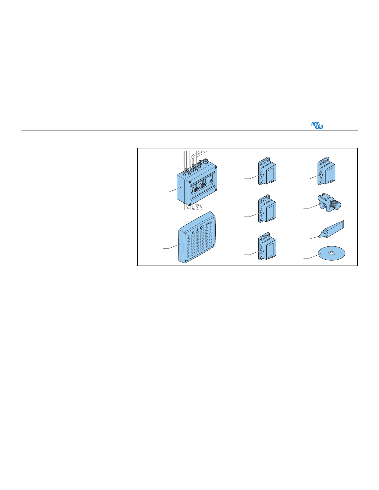
1.3 Overview 5
Overview of components................... 5
2Installation................................................ 6
2.1 Install the system............................... 6
Precautions .......................................6
Calculate the needed power.............. 7
Select the nodes................................ 8
Routing from the appliance(s) to the
node ..................................................9
Routing of the bus cable and main
fuse box........................................... 10
Install the main fuse box.................. 11
Connect to the battery .....................12
Connect the direct power nodes
(DPN) ..............................................13
Install the switch panel ....................14
Install the node ................................16
2.2 Configure the system.......................19
Priority .............................................19
Switch mode ....................................19
Navigation lights ..............................19
Bilge-pump ......................................19
Feedback defective lamp/cable .......19
Reconfigure .....................................19
Store the configuration ....................19
2.3 Start the system the first time ..........20
Configure one switch to one node ...21
Configure one switch to more than
one node..........................................21
Configure more than one switch to
one node..........................................22
Change priority ................................22
Change feedback of defective
lamp/wire .........................................23
Delete connection between switch
and node..........................................24
3Operation .............................................. 25
Push button panel overview............ 25
Switch on the system...................... 26
Background light ............................. 26
Warning lights ................................. 27
Indications of the appliances .......... 27
Detection of doors and hatches ...... 28
Direct Power Node (DPN)............... 29
Switch off the system...................... 30
4Maintenance.......................................... 31
4.1 Troubleshooting .............................. 31
4.2 Replace the node............................ 32
If no new nodes are available: ........ 32
4.3 Technical specifications.................. 33
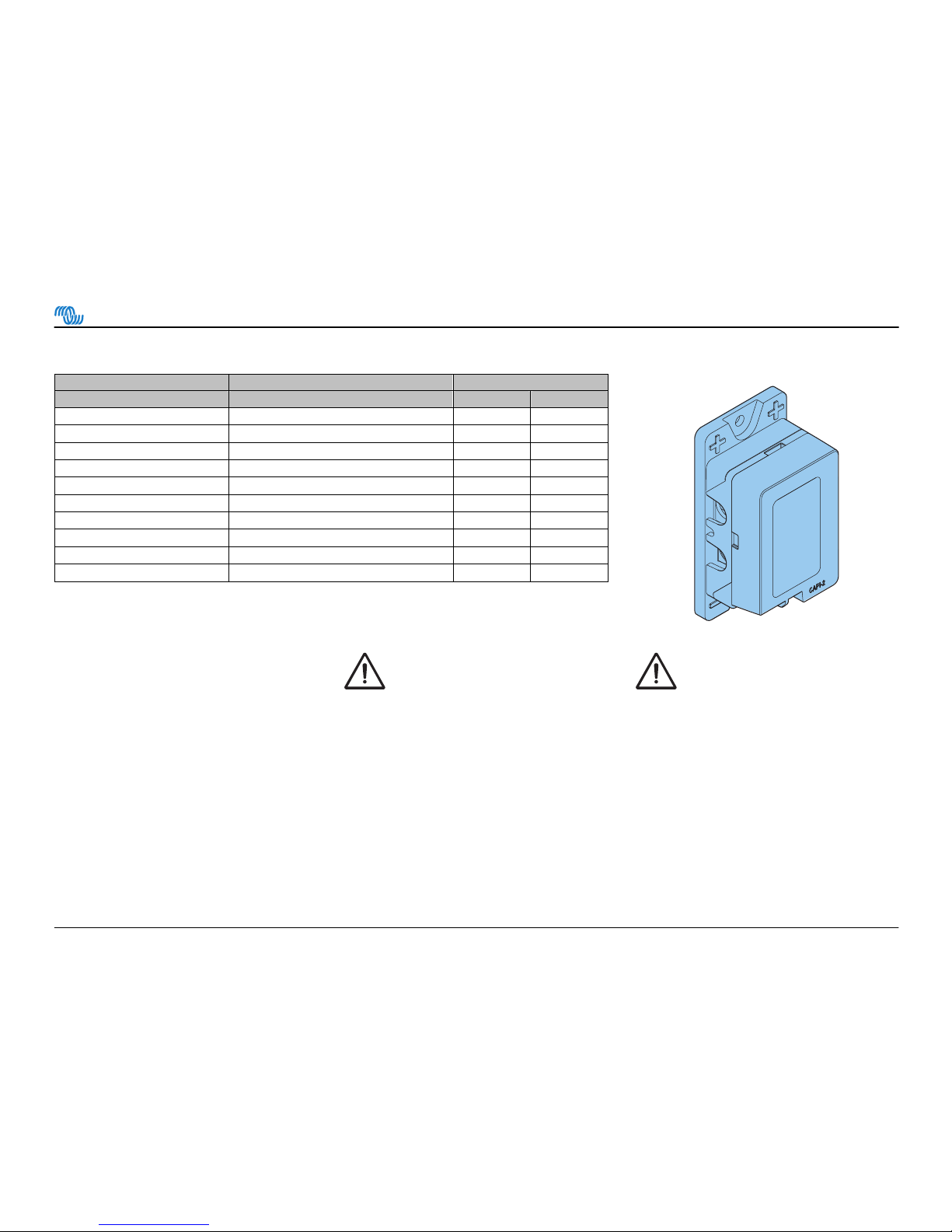
4.4 Spare parts 34
5Appendix ............................................... 36
Configuration table (3x)................... 36

Installation & operation manual
4
victron ener
gy
B L U E P O W E R
1 Introduction
1.1 General
VE.Net DC
Congratulations on purchasing a VE.Net
DC bus power distribution system for
your vessel. The system is delivered as
a set and can be assembled according
to CE standard. It is essential therefore
to follow the installation instructions
carefully.
VE.Net DC is a modern electronically
controlled bus system. Special built in
features reduce the risk of a cable fire or
a low-voltage situation.
Features
Built in features include:
• An electronic fuse for each load. The
fuse can be reset with the switch
push button.
• All warnings are both visual and
audible.
• A warning for broken (navigation)
light or wire.
• A warning for overloads. The
appliance turns off automatically.
• A warning for low voltage. The
appliance turns off automatically.
• An adjustable background light in the
switch panel.
About this manual
This user manual describes the
installation and operation of the VE.Net
DC system. Read this manual carefully
before use or operation of the product. In
case you have any doubt about a
procedure contact your dealer.
1.2 Safety
General
Observe all safety instructions. Use this
product only for the purpose it is
intended for. Please contact your dealer
immediately if a potential danger arises
during the use of this product.
Modifications
Modifications to the product are not
permitted.
Service and technical support
For information concerning specific
settings, maintenance or repair work,
contact your local dealer.

Installation & operation manual
5
victron ener
gy
B L U E P O W E R
1.3 Overview
Overview of components
A. Cable harness including:
• 10 A fuse
• 50 A fuse
• 10 A. direct power node
• 20 A. direct power node
• 2 × 15 m. bus cable
• 8 m cable for push button panel
• 8 m cable for bilge-pump
• 8 m cable for instruments
B. Push button panel
C. 3 A. power nodes
D. 10 A. power nodes
E. 16 A. power nodes
F. Sensor node for bilge-pump
G. Cable cutter
H. DC 4 compound (tube)
I. CD labels
B(1x)
A(1x)
C(5x)
16
10
3
G(1x)
I(1x)
H(1x)
D(8x)
E(2x)
F(1x)
S

Installation & operation manual
6
victron ener
gy
B L U E P O W E R
2 Installation
2.1 Install the system
Precautions
Observe the following when you wire the
system:
1. Never install any components above
batteries or fuel tanks.
2. Never install components or cables
near heat sources that may melt the
insulation.
3. Never expose components or
cables to oil or grease.
4. Never install components when
there is a risk of exposure to water.
5. Never use twist-on connectors.
• Always use insulation barriers to
prevent a short circuit of exposed
terminal connectors.
• Always use the correct tool.
• Always take the necessary
precautions to protect the
components and cables from
damage.
• Always clamp the wires at least
every 30 cm (12”).
• Protect cables that pass bulkheads
or structural members against
damage by grummets or equivalent
means.
• Protect components and wires with
sheets, conduits or equivalent means
when there is a risk of physical
damage.
• All wires must be fire resistant, fine-
stranded and tinned.
• Always use the correct cable
diameter and colour. This is indicated
on the node.
• Wires outside the motor
compartment must be rated at
minimum 60 °C / 140 °F.
• Wires inside the motor compartment
must be rated at minimum 70 °C /
158 °F.

Installation & operation manual
7
victron ener
gy
B L U E P O W E R
Calculate the needed power
Calculate the total power and the
amount of nodes for each bus-cable
before you start installation.
1. Calculate for each single appliance
or groups of appliances the power
needed.
• 1 A per 10 W for a 12 V system
• 0,5 A per 10 W for a 24 V system
2. Divide the appliances as evenly as
possible between the two bus cables.
Each bus cable can have a
maximum load of 50 A.
3. Select the node with the correct
amperage. Refer to Select the
nodes.
4. Write down the configuration of the
nodes in the Configuration tables.
Refer to the Error! Not a valid
bookmark self-reference..
Warning!
Do not install nodes in a
petrol engine compartment or
a gas locker. There is a risk
of ignition and explosion.
Note: Appliances connected to the
Direct Power Nodes do not influence the
total power on a bus cable.

Installation & operation manual
8
victron ener
gy
B L U E P O W E R
Select the nodes
We recommend the following set-up:
Node Appliance Cable Diameter
(mm2) (AWG)
3 A Navigation light 1,5 16
Interior light
10 A Deck light 1,5 16
Instruments
Interior light
Power outlet
Refrigerator
16 A Fresh water pump 2,5 14
Bilge-pump
Sensor node on/off Automatic switch bilge-pump 1,5 16
Note: Connect the delivered sensor
node to the automatic switch of the bilge-
pump.
Caution!
The node triggers when there
is more power applied than
specified.
Caution!
Connect the radar, compass
GPS and bilge-pump to a
direct power node. The direct
power nodes are located in
the main fuse box.

Installation & operation manual
9
victron ener
gy
B L U E P O W E R
Routing from the appliance(s) to the node
Node
Node
1. Lay-out the wires from the appliance
to where the node will be placed.
2. Cut the wires to the correct length.
Allow extra length to tighten up the
cables with tie-wraps. Refer to the
drawing.
3. Attach the connectors on the end of
the wires.
4. Lay-out single appliances directly to
the node. 5. Lay-out group appliances parallel to
the node.

Installation & operation manual
10
victron ener
gy
B L U E P O W E R
Routing of the bus cable and main fuse box
max. 200 cm
80"
1. Lay-out the bus-, instrument-,
switchboard- and bilge-pump cables
and the main fuse box to where they
will be placed.
Note: Make sure the main fuse box
is easy to access.
Warning!
Do not install nodes in a
petrol engine compartment or
a gas locker. There is a risk o
f
ignition and explosion.
Note: Make sure that the cable between
the fuse box and the battery has a
maximum length of 200 cm (80”).
Warning!
If the +cable (red) between
the main fuse box and the
battery is longer than 200 cm
(80”), it needs a fuse of 80 A
at the battery.

Installation & operation manual
11
victron ener
gy
B L U E P O W E R
Install the main fuse box
1. Remove the cover of the main fuse
box.
Note: Make sure the main fuse box
is easy to access.
2. Install the main fuse box on a
suitable surface. 3. Set the fuses in the OFF position.
4. Replace the front cover.
Warning!
Make sure all fuses are set in
the OFF position.

Installation & operation manual
12
victron ener
gy
B L U E P O W E R
Connect to the battery
15 mm
5/8"
20 mm
6/8"
1. If necessary, adjust the length of the
bus wires at the main fuse box.
2. Remove the cover of the main fuse
box.
3. Loosen the screw to remove the wire
on the fuse.
4. Cut the wire.
5. Remove 15 mm (5/8“) of the
insulation at the end of the wire. Use
the cable cutter to cut the insulation.
6. Place the wire back on its place.
7. Tighten the screw to secure the wire.
8. Clamp the bundles of + (red) and –
(black) battery wires with at least
20 mm (6/8") distance in between.
9. Connect the red cable to the +
terminal on the battery.
10. Connect the black cable to the -
terminal on the battery.
Note: Do the procedure for one wire
at a time. Warning!
Follow the instructions
properly to reduce the risk of
future shortcut with possible
fire.
Warning!
Make sure there is no risk of
physical damage for the
cables. In case there is a risk,
protect the cables with
grummets or equivalent.

Installation & operation manual
13
victron ener
gy
B L U E P O W E R
Connect the direct power nodes (DPN)
Fusebox
Max 10 A
DPN
12
11
12
11
30 cm
12"
1. Start from the main fuse box.
2. Clamp the 10 A Direct Power Node
(DPN) wires to the instruments.
If necessary, install a multiple fuse
box with a total of 10 A between the
different instruments and the node.
Refer to the illustration.
3. Clamp the 20 A DPN wires to the
bilge-pump.
Note: Do not connect the wires to the
appliances mentioned.
4. Attach the wires for the push button
panel. Leave 30 – 40 cm (12 – 16“)
extra length for easy connection of
the switch panel.
5. Attach the wires with a clamp every
30 cm (12“).
Note: Clamp the wires of the
instruments, bilge-pump and switch
board separated from the bus cable.
Caution!
The instruments and VHF
may need a separate fuse.
Refer to the instrument user
manual.

Installation & operation manual
14
victron ener
gy
B L U E P O W E R
Install the switch panel
O
20 mm
6/8"
1. Remove the cover of the switch
panel.
Note:
• Handle the cover with the
electronics with care.
• Do not touch the electronics.
• Place the cover with the
electronics in the box during
installation.
2. Feed the wires through a 20 mm
(6/8“) hole.
3. Feed the wires through the back
panel.
3. Install the back panel on a suitable
surface.

Installation & operation manual
15
victron ener
gy
B L U E P O W E R
Violet
Black
Red
Bus
GND
VBAT
4. Insert the labels in the cover.
Note:
• Switch 1 and 4 are reserved for
the bilge-pump.
• If necessary, make new labels
with the delivered CD.
• Use an overhead sheet to print
the labels.
5. Connect the wires to the electronics. 6. Replace the front cover.

Installation & operation manual
16
victron ener
gy
B L U E P O W E R
Install the node
2 mm
1/16"
Note: Start with the node closed to
the main fuse box.
1. Install the node base onto a suitable
surface.
Note:
• Align the side of the node marked
with + with the red bus cable
• Align the side of the node marked
with –with the black bus cable.
2. Push the wires into the base.
3. Mark the places of the clips on the
wires.
Warning!
Do not use the node base and
the clips more than one time.
Mounting deforms the clips
and base.
4. Cut the insulation with the cable
cutter.
5. Bend the wire several times until
2 mm (1/10”) of the conductors are
exposed.

Installation & operation manual
17
victron ener
gy
B L U E P O W E R
6. Push the clips onto the wire. Make
sure the clips make contact with the
exposed wires.
7. Put some DC4 compound around the
clips.
8. Push the clips into place to secure.
9. Repeat these steps for the other
wire.
10. Put some DC4 compound around the
violet wire. Put the compound on the
place of the single clip.
11. Push the wire into its position.
12. Use a hammer to secure the clip in
the base.

Installation & operation manual
18
victron ener
gy
B L U E P O W E R
30 cm
12"
13. Place the middle cover
14. Attach the proper node. 15. Attach the connectors to the wires
and clamp them accordingly.
Caution!
Do not connect the wires to
the node. This will be done
during the configuration of
the system.
16. Attach the wires with a clamp every
30 cm (12”). Allow some space for
additional nodes to install.
17. On the end of the bus cable:
Cut the bus cables to the proper
length and insulate them with
insulating tape.

Installation & operation manual
19
victron ener
gy
B L U E P O W E R
2.2 Configure the system
Priority
The node priority is used when there is
an overload or low voltage situation. The
nodes with a low priority turn off first to
make sure important systems remain in
operation. Therefore it is important to set
the priority of each node correctly.
The priority is automatically set in the
order of configuring the nodes. The first
configured nodes are set to the highest
priority.
Switch mode
The switch buttons can be set to two
different switch modes:
• Toggle mode:
When the switch is pushed, the
appliance functions until the switch is
pushed again. Use this mode for the
refrigerator, lights etc.
• Direct mode:
The appliance functions as long as
the switch is pushed. Use this mode
for the horn, winch etc.
Navigation lights
There are three options:
1. Configure each lamp to a separate
node, but to the same switch. The
switch indicates malfunction, but not
which light is defective.
2. Configure each lamp to a separate
switch and a separate node. The
indication shows which light is
defective.
3. Configure each lamp to a separate
node, but to the same switch.
Combined with a VE.Net DC
Navigation light board it is easy to
see which light is defective.
Bilge-pump
The bilge-pump and its sensor node do
not need to be configured. They are set
in the factory on switch 1 (automatic)
and switch 4 (manual) with the highest
priority. It is enough to connect the Direct
Power Node (DPN) wires to the pump
and the automatic switch to the sensor
node.
Feedback defective lamp/cable
The system indicates whether a
lamp/wire is defective or when a motor is
not running. It is possible to configure
the appliance not to include this
indication. This is recommended for
appliances such as 12 V outlet,
refrigerator, automatic pumps etc.
Reconfigure
1. Disconnect the appliance from the
node.
2. Follow the procedure as for normal
configuration.
Caution!
The reconfigured appliance is
set to the lowest priority.
Store the configuration
It is necessary to store each
configuration separately. To do this, turn
the push button panel off and on after
you finished the specific configuration.

Installation & operation manual
20
victron ener
gy
B L U E P O W E R
2.3 Start the system the first time
1. Switch on all main fuses. 2. Switch on the push button panel.
Warning:
In case of immediate alarm
(buzzer and lightening of the
polarity warning led):
1. Turn of the system through
the main fuses immediately.
2. Check the polarity at the
batteries. Change if necessary.
3. Turn on the system again.
See chapter Maintenance.
3. Proceed with configuration.
Table of contents
Other Victron energy Power Distribution Unit manuals

Victron energy
Victron energy MultiPlus-II 12/3000/120-32 User manual

Victron energy
Victron energy Smart BatteryProtect 12/24V User manual

Victron energy
Victron energy miniBMS User manual

Victron energy
Victron energy Battery Protect Series User manual

Victron energy
Victron energy BatteryProtect 48V 100A User manual

Victron energy
Victron energy Smart BMS CL 12/100 User manual

Victron energy
Victron energy BatteryProtect User manual

Victron energy
Victron energy Smart BatteryProtect 12/24V User manual