BOSSCO ROD-10 User manual
UBOSS
RDOD-10
DIGITAL.
OSL?
INSTRUCTIONS
@
Please
read
the
instructions
carefully.
FEATURES
The
BOSS
RDD-10
is
a
compact
yet
versatile
digital
delay
machine.
By
changing
the
delay
time
range(9
steps)
and
modulation,
you
can
enjoy
various
types
of
effects;
not
only
echo
but
also
flanging
or
doubling
chorus
effect,
etc.
Also,
the
Delay
Tone
Knob
allows
you
to
make
a
mild
echo
like
an
analog
delay’s
as
well
as
a
sharp
echo.
Two
RDD-10‘s
can
be
set
up
through
their
Modulation
Buses
for
modulation
sync.
Moreover,
the
phase
of
the
modulation
can
be
inverted
with
the
Polarity
Switch,
creating
wide
variety
of
stereo
effects.
Both
standard
phone
and
pin
jacks
are
provided
for
an
Output
or
input,
and
more,
the
Level
Switch
(-20dBm
/
-—10dBm}
is
featured,
allowing
applied
setups
su-
ch
as
with
audio
and
video
equipment
as
well
as
usual
use
with
musical
instruments.
The
RDD-10
is
one
of
the
BOSS
Micro
Studio
Series,
and
any
two
sets
of
them
can
be
set
up
on
the
Standard
19”
rack{ElA-1U)
by
using
the
optional
rack
mount
adaptor
RAD-10.
aa
Radio
and
television
interference
“Warning
—
This
equipment
has
been
verified
to
comply
with
the
limits
for
a
Class
B
computing
device,
pursuant
to
Subpart
J,
of
Part
15,
of
FCC
rules.
Operation
with
non-certified
or
nonverified
equipment
is
likely
to
result
in
interference
to
radio
and
TV
reception.”
The
equipment
described
in
this
manual
generates
and
uses
radio-frequency
energy.
If
it
is
not
installed
and
used
properly,
that
is,
in
strict
accordance
with
our
instructions,
it
may’
cause
interference
with
radio
and
television
reception.
This
equipmeni
has
Veen
Sted
SIG
ToOUAG
tT
COIN
ply
with
the
simits
for
a
Class
8
computing
device
in
accordance
with
the
specifications
in
Subpart
J,
of
Part
15,
of
FCC
Rules.
These
rules
are
designed
to
provide
reasonable
protection
against
such
an
inter-
ference
in
a
residentiat
installation.
However,
there
is
no
quarantee
that
the
interference
will
not
occur
in
a
particular
installation,
If
this
equioment
Goes
cause
interference
to
radio
or
televi-
sion
reception,
which
can
be
determined
by
turning
the
equipment
on
and
off,
the
user
is
encouraged
to
try
to
correct
the
interference
by
the
following
measure:
@Disconnect
other
devices
and
their
input/output
cables
one
at
a
time.
If
the
interference
stops,
it
Is
caused
by
either
the
other
device
or
its
1/O
cable.
These
devices
usually require
Roland
designated
shielded
I/O
cables.
For
Roland
devices,
you
can
obtain
the
proper
shielded
cable
from
your
dealer.
For
non
Roland
devices,
contact
the
manufacturer
or
deater
for
assistance.
lf
your
equipment
does
cause
interference
to
radio
or
television
reception,
you
can
try
iv
correct
ihe
interference
by
using
one
or
more
of
the
following
measures:
@Turn
the
TV
or
radio
antenna
until
the
interfer:
ence
stops.
'
@Move
the
equioment
to
one
side
or
the
other
of
the
TV
or
radio,
@Move
the
equipment
farther
away
from
the
TV
or
radio,
@Plug
the
equipment
into
an
outlet
that
is
on
a
dif-
ferent
circuit
than
the
TV
or
radio,
(That
is,
make
certain
the
equipment
and
the
radio
or
television
set
are
on
circuits
controlled
by
different
circuit
breakers
or
fuses.)
@Consider
installing
a
rooftop
television
antenna
with
coaxial
cable
lead-in
between
the
antennas
and
TV.
If
necessary,
you
should
consult
your
dealer
or
an
expertenced
radio/television
technician
for
addi-
tional
suggestions,
You
may
find
helpful
the
follow-
ing
booklet
prepared
by
the
Federal
Communica-
tions
Commission:
“How
to
identify
and
Resolve
Radio-TV
Interfer-
ence
Problems”
This
booklet
is
available
from
the
U.S.
Government
Printing
Office,
Washington,
D.C,,
20402,
Stack
No.
004-000-00345-4.
oe
Bescheinigung
des
Herstellers
/Importeurs
Hiermit
witd
bescheinigt.
ds8
der/die/das
nn
DIGITAL
DELAY
ROO-10
|,
(Cerne,
Typ
Secentewngh
in
Obereinstimmung
mit
dea
Sestimmungen
der
Amtsb!
Vig
1046/1984
funk-entstort
ist.
Der
Deutschen
Bundespost
wurde
dat
Inverkehrbsingen
cietes
Gerates
angezeign
und
die
Serechtiguny
zur
Oberprifung
der
Serie
auf
Einhaltung
der
Sestimmungen
eingecdynt.
Roland
Corporation
Osaka/Japan
idnidi
ikhd
in
cntnktiyeiiniaaratia
Rape
Get
ern
tat
bern
Pros
hens
MPANEL
DESCRIPTIONS
<FRONT
PANEL>
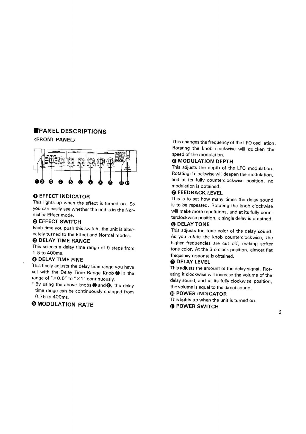
@
EFFECT
INDICATOR
This
tights
up
when
the
effect
is
turned
on.
So
you
Can
easily
see
whether
the
unit
is
in
the
Nor-
mal
or
Effect
mode.
@
EFFECT
SWITCH
Each
time
you
push
this
switch,
the
unit
is
alter-
nately
turned
to
the
Effect
and
Normal
modes.
©
DELAY
TIME
RANGE
This
selects
a
delay
time
range
of
9
steps
from
1.5
to
400ms.
@
DELAY
TIME
FINE
This
finely
adjusts
the
delay
time
ra
nge
you
have
set
with
the
Delay
Time
Range
Knob
@
in
the
range
of
”x0.5”
to”
x1”
continuously.
”
By
using
the
above
knobs
@
and@,
the
delay
time
range
can
be
continuously
changed
from
0.75
to
400ms.
©
MODULATION
RATE
This
changes
the
frequency
of
the
LFO
oscillation.
Rotating
the
knob
clockwise
will
quicken
the
speed
of
the
modulation.
@
MODULATION
DEPTH
This
adjusts
the
depth
of
the
LFO
modulation.
Rotating
it
clockwise
will
deepen
the
modulation,
and
at
its
fully
counterclockwise
position,
no
modulation
is
obtained.
@
FEEDBACK
LEVEL
This
is
to
set
how
many
times
the
delay
sound
is
to
be
repeated.
Rotating
the
knob
clockwise
will
make
more
repetitions,
and
at
its
fully
coun-
terclockwise
position,
a
single
delay
is
obtained.
@©
DELAY
TONE
This
adjusts
the
tone
color
of
the
delay
sound.
As
you
rotate
the
knob
counterclockwise,
the
higher
frequencies
are
cut
off,
making
softer
tone
color.
At
the
3
o'clock
position,
almost
flat
frequency
response
is
obtained.
©
DELAY
LEVEL
This
adjusts
the
amount
of
the
delay
signal.
Rot-
ating
it
clockwise
will
increase
the
volume
of
the
delay
sound,
and
at
its
fully
clockwise
position,
the
volume
is
equal
to
the
direct
sound.
@
POWER
INDICATOR
This
lights
up
when
the
unit
is
turned
on.
@
POWER
SWITCH
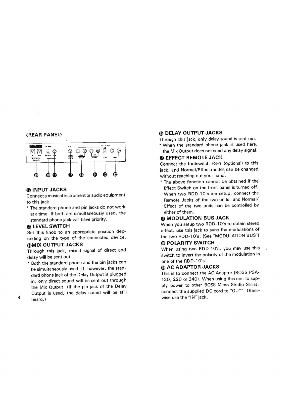
<REAR
PANEL>
Wd
ery
A
alah
im
CAAr
-
e
.
‘
I
Lj
we
Ge
@®
INPUT
JACKS
Connecta
musical
instrument
or
audio
equipment
to
this
jack.
*
The
standard
phone
and
pin
jacks
do
not
work
at
atime.
If
both
are
simultaneously
used,
the
standard
phone
jack
will
have
priority.
@®
LEVEL
SWITCH
Set
this
knob
to
an
appropriate
position
dep-
ending
on
the
type
of
the
connected
device.
@MMIX
OUTPUT
JACKS
Through
this
jack,
mixed
signa!
of
direct
and
delay
will
be
sent
out.
*
Both
the
standard
phone
and
the
pin
jacks
can
be
simultaneously
used.
If,
however,
the
stan-
dard
phone
jack
of
the
Delay
Output
is
plugged
in,
only
direct
sound
will
be
sent
out
through
the
Mix
Output.
(if
the
pin
jack
of
the
Delay
Output
is
used,
the
delay
sound
will
be
still
heard.)
@®
DELAY
OUTPUT
JACKS
Through
this
jack,
only
delay
sound
is
sent
out.
*
When
the
standard
phone
jack
is
used
here,
the
Mix
Output
does
not
send
any
delay
signal.
@
EFFECT
REMOTE
JACK
Connect
the
footswitch
FS-1
(optional)
to
this
jack,
and
Normai/Effect
modes
can
be
changed
without
reaching
out
your
hand.
*
The
above
function
cannot
be
obtained
if
the
Effect
Switch
on
the
front
panel
is
turned
off.
When
two
RDD-10’s
are
setup,
connect
the
Remote
Jacks
of
the
two
units,
and
Normal/
Effect
of
the
two
units
can
be
controlled
by
either
of
them.
(P
MODULATION
BUS
JACK
When
you
setup
two
RDD-10’s
to
obtain
stereo
effect,
use
this
jack
to
sync
the
modulations
of
the
two
RDD-10's.
(See
“MODULATION
BUS")
@
POLARITY
SWITCH
When
using
two
RDD-10's,
you
may
use
this
switch
to
invert
the
polarity
of
the
modulation
in
one
of
the
RDD-10’'s.
@®
AC
ADAPTOR
JACKS
This
is
to
connect
the
AC
Adaptor
(BOSS
PSA-
120,
220
or
240).
When
using
this
unit
to
sup-
ply
power
to
other
BOSS
Micro
Studio
Series,
connect
the
supplied
DC
cord
to
“OUT”.
Other-
wise
use
the
“IN”
jack.

MCONNECTIONS
AC
Adaptor
BOSS
PSA-120,
220,
240(Qptional}
To
AC
Adaptor
Jack
To
other
BOSS
Micro
Studio
Series
Refer
to
“MMODULATION
BUS”
USE
8OSS
PSA
ACAPTOR
ONLY
POLARITY
BUS
—_—_—_———
Ali
the
BOSS
Micro
Studio
Sertes
show
the
current
draw
here.
SEND
RETURN
6
2
MIXER
(BOSS
BX
Series,
etc.)
Footswitch
FS-1
(optional)
To
OUTPUT
*
Normally,
the
Mix
Output
is
to
be
used,
but
the
Delay
Output
should
be
used
to
return
the
delay
signal
to
the
Echo
Return
jack
of
the
mixer.
Fo
INPUT
Video
Cassette
Recoder
Guitar
a
el
ae
on
anna
n
CO
Player
etre
MTOM
ATTRA
Electric
Keyboard
Video
Dise
Player
fa
senDARNOR
es
==
Coie
Tape
Retoder
FM/T¥
Tuner
M@
Featuring
Low
Noise,
RDD-10
can
also
have
place
in
AV
system
for
creating
special
sound
effect.
2OHLOO
Pre
Mam
Amptifier
Guitar
Amplifier

MOPERATIONS
@
Set
the
controls
on
the
panel
as
shown
below.
ots
reat
Os
©:
-~
.
=
cae
=iP
.
wee
Ot
we,
i!
aT
oe
ate
ale
J
‘,
*
‘,
~
4
* .
-
+ .
al
=
==
*
.
4
.
ia
~
|
‘? .*
+;
"
~
“tw
wu
mate
OePTH
BA
8
thes
YY
“r
:
A
=
>
4
=
+
“7
.
.
_
mt
atria
nie
sok
yee,
SLAY
Si
2CTY-
00-10
a
ae
-
=
=
TOM.
advise
@
Set
the
Level
Switch
to
the
appropriate
posit-
ion
depending
on
the
type
of
the
connected
unit.
*
If
it
is
the
noise
that
you
wish
to
avoid
more
than
anything,
set
the
switch
to
“—20dBm”.
Changing
the
position
of
the
Level
Switch
will-
not
affect
the
volume.
()
Set
a
delay
time
by
using
the
Delay
Time
Ran-
ge
and
the
Fine
Knobs.
1.5
to
6.Oms
is
requ-
ired
for
a
flanging
effect,
12.5
to
50ms
for
a
chorus
effect
and
50
to
400ms
for
delay(echo)
effect.
@
Adjust
the
rate
of
the
LFO
modulation
with
the
Modulation
Rate
Knob,
and
the
depth
with
the
Depth
Knob.
Usually,
set
the
rate
slow
and
the
depth
deep
for
a
flanging
effect,
and
set
both
knobs
to
the
center
positions
for
chorus.
For
a
delay{echo)
effect,
set
the
Dep-
th
Knob
to
“MIN".
()
Adjust
the
Feedback
Level
with
the
Feedback
Level
Knob.
At
the
“MIN”
position,
single
delay
is
obtained.
When
the
delay
time
is
long
(
=ec-
ho
effect),
the
Feedback
Level
Knob
serves
to
set
how
many
times
the
delay
sound
is
to
be
repeated.
When
it
is
set
short(=flanging
effe-
ct),
the
same
knob
serves
to
adjust
the
reson-
ance.
*
As
you
rotate
the
Feedback
Level
Knob
clo-
ckwise,
the
unit
may
start
oscillating.
@
Make
a
tone
color
you
like
with
the
Delay
Tone
Knob.
@
Adjust
the
volume
of
the
delay
sound
with
the
Delay
Level
Knob.
At
the
“MAX”
position,
the
delay
sound
is
equal
to
the
direct
sound.
*
Both
the
standard
phone
and
the
pin
of
the
Output
Jacks
can
be
simultaneously
used.
If,
however,
the
standard
jack
of
the
Delay
Out-
put
is
plugged
in,
the
Mix
Output
sends
out
no
delay
signal
but
only
the
direct
signal.
In
this
way,
the
direct
and
delay
sounds
are
sep-
arately
send
out,
resulting
in
stereo
effect.

BMODULATION
BUS
By
connecting
two
RDD-10’'s
through
their
Mo-
|
*
The
left
RDD-10
is
used
as
a
Master,
and
the
dulation
Buses,
various
delay
effects
can
be
ob-
other
as
a
Slave.
tained.
1
Set
up
two
RDD-10’s
as
shown
below.
AC
Adaptor
AC
Adaptor
BOSS
PSA-120,
220,
240
BOSS
PSA-120,
220,
240
Standard
Phone
Piug
«-»
Standard
Phone
Plug
y
MASTER
TO
8o
299
99to
mo
B¢
sto00COU
ey
eo
Mia
|
i
Naa
fess
nt
hs
a
ee
Ee
3
acannon
2
oi
Nae
©
;
;
Consumer-type
'
l
'
Power
Amplifiert
—
—10dBm)
'
'
|
Stereo
Amplifier
Tape
Recorder
Guitar Guitar
Speaker
Amplifier
Amplifier
*
By
connecting
these
two
devices
through
their
Remote
Jacks,
you
can
turn
on
or
off
the
Effects
of
the
both
devices
simu-
taneously.
SLAVE
=
=e
#
:
Video
Cassette
Recoder
Guitar
an
a
=
Electric
Keyboard
video
One
Player
a
PETTEE
TY
sete
Tape
Recoder
FM/T¥
Tuner
*
The
RDD-10
features
the
frequency
response
that
almost
covers
the
audible
range
of
men,
therefore
successful
effect
can
be
expected
7
by
connecting
to
audio
and
video
equipment.

2
Set
the
Delay
Time
Fine
and
the
Modulation
Rate,
Depth
Knobs
as
shown
below.
MASTER
*
To
avoid
excessive
amount
of
two
mixed
mod-
ulation,
set
the
Delay
Time
Fine
Knob
on
the
Slave
unit
to
the
center
position,
and
the
Dep-
th
Knob
to
the
“MIN”
position.
With
the
Depth
set
to
the
“MIN”
position,
the
Rate
has
Knob
no
effect.
3
To
make
the
sound
you
like,
move
the
controls
on
the
froht
panels
except
the
Delay
Time
Fine
and
the
Modu-
lation
Depth
Knobs
on
the
Slave.
MASTER
bee
oo
eee
]
Sayre
tea
————_4*{
___.
BB0sSs
ses
galeee)
*Inverting
the
polarity
of
the
modulation
on
*
When
two
RDD-10’s
are
set
up
and
the
Effect
either
unit
may
be
interesting.
Remote
Jacks
of
the
two
units
are
connected,
Normal/Effect
of
the
both
units
can
be
chang-
ed
by
pushing
the
Effect
Switch
on
either
unit.

@
Example
Settings
©
Flanger
CEL
aT
Tat
Pate
gle
attra,
wvitte,
=©O2
©0:
al
ww.
-
"> ao
=e
ep
os
é
‘
Ft
watt
atu
wl
a
a
6
Le
~
Naa
pa
OPFECT
RANGE
Ime
acm
ater
aY
Tat
——
ATO
|
ffi
eat
TONG
aie
=
=
aTIOW
FtzpeaeK
ee,
1...)
er
Seoass
'
1
1 ;
Pe
ae,
J
ote
fe
a
ate
‘,
2
ale
a
:
= =
Lt.
~ROD-10
?
.
Ps
”
<3}
&
ew"
oy
4
an]
wan
was
OLPTH
LeveL
omar
oe
<n
BeOS.
:
=RO0-10
FEeCe
ACK
te
pares
10
=Oni
Ox
0:
O:
Os
o-
rt
nd
Let
a
peoss
‘
.f,
‘©
EY:
“|
5
00-10
a
eS
er
a
nd
—
Fi
oeacK
Or
‘
*
pa
|
ee
CyFect
nuit
ats
age
.
un
poss
|
pIGhAL
=
Setting
Vlemo
oO
ATI
|
ECA
met
Odi
ay
Tea
anon
te,
tlie,
gtley
on iy
-
° .
=]-
~
*
AS
.
.
coe
‘
ir
inal
.4
CFICT
=
RANE
(me
WATE
Of7TH
=- oe
ac
EFSECT
an
an
B26
06
:
j10-016/8
»
ae
7
‘
af
GFFICT
=
BAMEtan
=
ater
cai.
a
Feat
Latis,
foes
alee,
ros
=O)
i
an
pa
ae
ee
GFIGT
=
RANK
e4
‘eas
wal
=a
acre
VGN
[oy
SX
-
“00-10
ca
=
Otiar
Rass
—_
BOS

10
MNOTES
®
Be
sure
to
use
the
BOSS
AC
Adaptor
PSA-120,
220
or
240
depending
on
the
line
voltage
sy-
stem
in
your
country.
@VWhen
you
are
using
only
one
AC
adaptor
for
supplying
power
to
more
than
one
unit,
please
be
sure
that
the
total
current
draw
does
not
exceed
200mA.
Please
note
that
two
AC
ada-
ptors
are
needed
for
supplying
power
to
two
sets
of
the
RDD-10's
@
Avoid
operating
this
unit
in
excessive
heat
or
humidity
or
where
tt
may
be
affected
by
dust.
@
Please
never
remove
the
cabinet
from
the
unit.
@When
you
use
only
Micro
Studio
Series
with-
out
optional
Rack
Mount
Adaptor
“RAD-10”,
please
attatch
the
rubber
feet.
Refer
to
figure.
@
AC
ADAPTOR
BOSS
PSA-120,
220
or
240
(Optional)
Be
sure
to
use
the
Adaptor
BOSS
PSA-Series.
Using
any
other
type
of
adaptor
may
cause
trou-
ble.
MRACK
MOUNTING
The
RDD-10
is
one
of
the
BOSS
Micro
Studio
Series,
and
any
two
of
them
can
be
mounted
in
a
standard
19”
rack
{EIA-1U)
by
using
the
opti-
onal
Rack
Mount
Adaptor
RAD-10.
Remove
the
rubber
feet
from
the
bottom
of
the
units,
fix
the
units
on
the
Rack
Mount
Ada-
ptor
with
the
supplied
screws,
then
place
the
whole
set
on
the
rack.
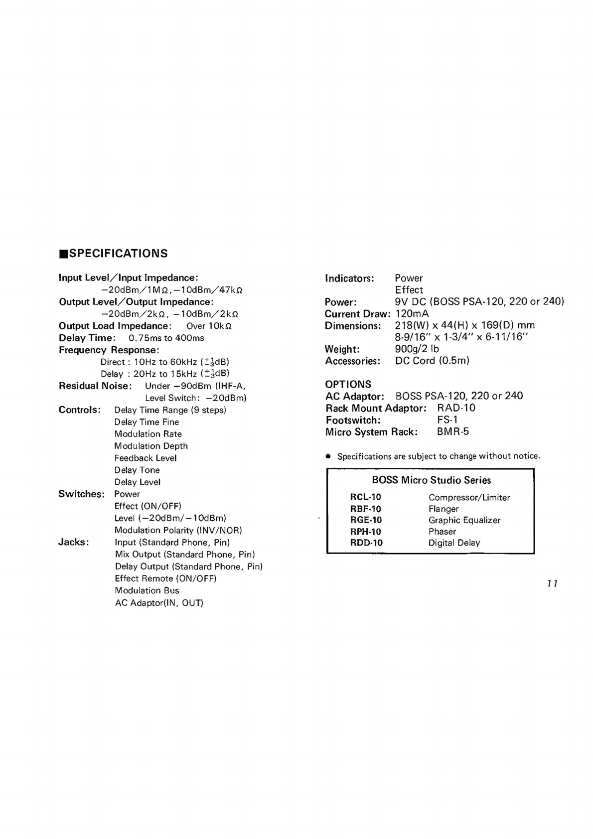
MSPECIFICATIONS
input
Level
/Input
Impedance:
—20dBm
/1MQ,-—10dBm/47kQ
Output
Level/
Output
Impedance:
—20dBm/2kQ,
—10dBm/2k9
Output
Load
Impedance:
Over
10kQ
Delay
Time:
0.75ms
to
400ms
Frequency
Response:
Direct
:
10Hz
to
GOkHz
(+4dB)
Delay
:
20Hz
to
15kHz
(*3dB)
Residual
Noise:
Under
—90dBm
(IHF-A,
Level
Switch:
—20dBm)
Controis:
Delay
Time
Range
(9
steps)
Delay
Time
Fine
Modulation
Rate
Modulation
Depth
Feedback
Level
Delay
Fone
Delay
Level
Switches:
Power
Effect
(ON/OFF}
Level
(—20dBm/—10dBm)}
Modulation
Polarity
{!INV/NOR)
Jacks:
Input
(Standard
Phone,
Pin)
Mix
Output
(Standard
Phone,
Pin)
Delay
Output
(Standard
Phone,
Pin)
Effect
Remote
{ON/OFF}
Modulation
Bus
AC
Adaptor({IN,
OUT)
indicators:
Power:
Current
Draw:
Dimensions:
Weight:
Accessories:
OPTIONS
AC
Adaptor:
Power
Effect
9V
DC
{BOSS
PSA-120,
220
or
240)
120mA
218(W)
x
44(H}
x
169{D}
mm
8-9/16"
x
1-3/4”
x
6-11/16”
900q/2
Ib
DC
Cord
(0.5m)
BOSS
PSA-120,
220
or
240
Rack
Mount
Adaptor:
RAD-10
Footswitch:
FS-1
Micro
System
Rack:
BMR-5
@
Specifications
are
subject
to
change
without
notice.
BOSS
Micro
Studio
Series
RCL-10
RBF-10
RGE-10
RPH-10
RDD-10
Compressor/Limiter
Flanger
Graphic
Equalizer
Phaser
Digital
Delay

OBOSS
Products
of
Roland
RDD-10
Instructions
printed
in
Japan
‘85
Sep.
C-3
Other manuals for ROD-10
2
Popular Power Distribution Unit manuals by other brands


MGE UPS Systems
MGE UPS Systems FlexPDU 12 IEC Installation and user manual

SMA
SMA Sunny Island MULTICLUSTER BOX 6.3 operating manual

Shure
Shure UA845 user guide

Ilsco
Ilsco SSI SpecPRO CSM 20 Series quick start guide

OEZ
OEZ RCD-BC0-E series Instructions for use

philippi
philippi STV 200 Series instruction manual

ASA Electronics
ASA Electronics versalogic VersaNet Manual instructions

Clever Electronics
Clever Electronics NPM2000 user manual

brennenstuhl
brennenstuhl WV 4/16 A IP44 manual

Rock Solid
Rock Solid RSM1-20AB-08N1 user guide

Limente
Limente Desk-2 S/S Assembling instructions

Eaton
Eaton ePDU G3HD Installation and connection manual