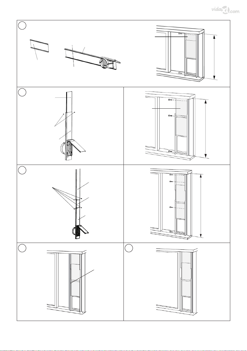
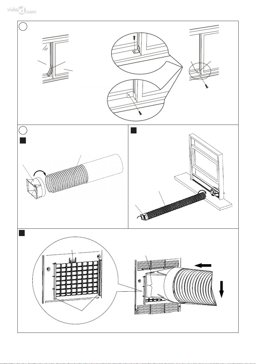
vidaXL 50762 Quick guide

Operang and safety instrucons
Bedienungs- und Sicherheitshinweise
Instrucons de sécurité et de fonconnement
Bediening en veiligheidsinstruces
Istruzioni per l’uso e la sicurezza
Instrukcja obsługi i bezpieczeństwa
Dri- och säkerhetsanvisningar
Instrucciones de uso y seguridad
Betjenings- og sikkerhedsanvisninger
Dris- og sikkerhetsinstruksjoner
Instruções de funcionamento e segurança
Instrucțiuni de ulizare și de siguranță
Navodila za uporabo in varnostna navodila
Kezelési és biztonsági utasítások
Provozní a bezpečnostní pokyny
Prevádzkové a bezpečnostné pokyny
Radne i sigurnosne upute
Käyö- ja turvaohjeet
Eksploatacijos ir saugos instrukcijos
Οδηγίες λειτουργίας και ασφάλειας
Инструкции за експлоатация и безопасност
Ekspluatācijas un drošības instrukcijas
Kasutusjuhised ja ohutusnõuded
50762

2| 50762
EN User manual ������������������ 15
DE Benutzerhandbuch ������������� 29
FR Manuel d’utilisation ��������� 46
NL Gebruikershandleiding �������� 62
IT Manuale dell’utente ���������� 78
PL Instrukcja obsługi ����������� 94
SE Bruksanvisning �������������� 111
ES Manual del usuario ���������� 125
DK Brugermanual ���������������� 141
NO Brukermanual ���������������� 156
PT Manual de utilizador �������� 171
RO Manual de utilizare ��������� 187
SI Navodila za uporabo ��������� 203
HU Felhasználói kézikönyv ������ 218
CZ Uživatelská příručka �������� 234
SK Používateľská príručka ������ 249
HR Korisnički priručnik �������� 264
FI Ohjekirja ������������������� 280
LT Vartotojo vadovas ����������� 294
GR Εγχειρίδιο χρήστη ����������� 310
BG Потребителско ръководство��� 328
LV Lietotāja rokasgrāmata ������ 345
EE Kasutusjuhend ��������������� 359
5 vidaXL.help
Language table

Images |3
30cm 30cm
30cm
X-FAN
ON/OFF
MODE
FAN
X-FAN
TURBO
HUMIDITY
FAN
AUTO
AIR
HEALTH
FILTER
TURBO
HOUR
ON/OFF
TEMP TIMER
SLEEP LIGHT
OPER
1
21 2 3 4
5 6 7 8 9
341
2
3
4
5
6
7
8
9
1011
12

| 507624
FAN
AUTO
OPER
AIR
HEALTH
FILTER
TURBO
ON/OFF
X-FAN
HOUR
HUMIDITY
ON/OFF
MODE
FAN
X-FAN
TURBO
TEMP TIMER
SLEEP LIGHT
5-1
(1)
(6)
(2)
(7)
(3)
(8)
(4)
(9)
(5)
(10)
(11)
(15)
(21)
(12)
(16)
(22)
(13)
(17)
(23)
(18)
(24)
(19)
(25)
(20)
(26)
(14)
5-2
5-3
(27)
(30)
(28)
(31)
(29)
(32)

5Images |
A
A
B
C
6-1 6-2
A
B
C
D
7-1
7-2

| 507626
F
B
D
E
E
7-3 8
9-1 9-2 9-3
10
11
1
23

7Images |
9
10
11
12
12
13
13
11
20.5”~37.4”
(520mm~950mm)
16
17
14
15
9
12
14
16
18
19
13
15
17
4
2
7
8
6
5
1
1
1
9
3
18
18
19
20
<20.5"(520mm)
2

| 507628
37.4”~56.7”
(950mm~1440mm)
21
20
21 22
918
1
17
22
23
24
25
27
28
26
23
24 25 26
14
12
12
11
11
13
13
9
16
17

9Images |
<20.5"
(520mm)
2
20.5”~37.4”
(520mm~950mm)
37.4”~56.7”
(950mm~1440mm)
27
28
29
30 31
1
1
1
1
9
9
3
18
18
18
21
20
17

| 5076210
1
2
3
23 22
24
26
25
27 28
32
33
(1)
(1)
(2)
(2)
(3)
(3)
(4)
(6)
(5)

11Images |
√ √
×
√
34
35
36 37
130cm

| 5076212
1 2
(4)
(1)
(8)
(9)
A
B
C
DE
F
G
H
I
J
K
1
3
4
7
8
9
2
5
6
10
13
11
12
38
39
40
(7)
FAN
AUTO
OPER
HEALTH
AIR
FILTER
TURBO
ON/OFF
X-FAN
HOUR
HUMIDITY
ON/OFF
MODE
FAN
X-FAN
TURBO
TEMP TIMER
SLEEP LIGHT

13Images |
A
C
A
B
1
2
3
4
5
41
42 43
FAN
OPER
AUTO
HEALTH
AIR
FILTER
TURBO
ON/OFF
X-FAN
HOUR
HUMIDITY
:
:
:
Air mode
Auto mode
Set temp.
Indoor ambient temp.
Outdoor ambient temp.
Up and down swing
Le and right swing
Timer On/Timer O
Turbo mode
Set temperature
X-fan
Health mode
Send signal
Set fan speed
Set me
Cool mode
Dry mode
Fan mode
Heat mode
Child lock
Light
Sleep mode
Operaon mode
Temp. display type
15
16
17
18
19
2
3
22
45
6
8
9
10
11
12
13
14
7
21
20
1
44
45
46 47

| 5076214
1 2
RT1 RT2 RT3 AP3
AP1
AP2
DISP1 DISP1
DISP2
DISP2 K201
REC AC-L
N3
BU
BN(BK)
BU(WH)
YEGN(GN)
PE
PE
PE
PE
BN
BU
BK BK
SA
N1
RD
C2
RD
M1
M2
CAP.
YEGN
YEC1RD
RD
CAP.
COMP
COMP.
COMP R(M)
L
N
C
S
YEGN
YEGN
13
12
10
9
14
11
15
16
1 2 3 4
5
6 7 8
48
49 50
51

15EN___User manual |
EN User manual
1 General warnings
Read all the instrucons and warnings carefully before using
this product. Failure to follow warnings and instrucons can
result in severe injury, death, or property damage. Before
installaon, check if all accessories are complete and without
damage. If not, contact customer service. Keep these
instrucons in a safe place for future reference. Use this
product with its original parts only. vidaXL cannot be held
responsible in the event of damage or injury due to incorrect
use of this product. The informaon contained in this manual is
believed to be correct at the me of prinng. However, vidaXL
reserve the right to change or modify any of the specicaons
without noce or obligaon to update exisng units. Repairs
should only be carried out by a specialist or a professional and
experienced technician. Never aempt to repair the product
yourself.
2 Symbol claricaon
This marking indicates that this product should not be disposed
of with other household wastes throughout the EU. To prevent
possible harm to the environment or human health from
uncontrolled waste disposal, recycle it responsibly to promote
the sustainable reuse of material resources. To return your used
device, please use the return and collecon systems or contact
the retailer where the product was purchased. They can take
this product for environmentally safe recycling.
See image 1
2.1 Explanaon of symbols
See image 2
1. Indicates a hazardous situaon that, if not avoided, will
result in death or serious injury.
2. Indicates a hazardous situaon that, if not avoided, could
result in death or serious injury.
3. Indicates a hazardous situaon that, if not avoided, may
result in minor or moderate injury.
4. Indicates important but not hazard-related informaon,
used to indicate risk of property damage.
5. Indicates a hazard that would be assigned a signal word
WARNING or CAUTION.
6. Appliance lled with ammable gas R290.
7. Before installaon and use, read the owner's manual.
8. Before installing the appliance, read the installaon
manual.
9. Before repairing the appliance, read the service manual
rst.
3 Warnings and personal safety
• Please read all the safety instrucons carefully before use
and keep this Instrucon / Installaon Manual for future
reference.
• WARNING! This appliance is not intended for use by
persons (including children) with reduced physical, sensory
or mental capabilies, or lack of experience and knowledge,
unless they have been given supervision or instrucon
concerning use of the appliance by a person responsible for
their safety. Children should be supervised to ensure that
they do not play with it.
3.1 The Refrigerant
• To realise the funcon of the air condioner unit, a special
refrigerant circulates in the system. The used refrigerant is
the uoride R290, which is specially cleaned. The refrigerant
is ammable and odourless. Furthermore, it can lead to an
explosion under certain condions.
• Compared to common refrigerants, R290 is a non-pollung
refrigerant with no harm to the ozone layer. The inuence
upon the greenhouse eect is also lower. R290 has very
good thermodynamic features which lead to really high
energy eciency. The units, therefore, need a less lling.
• Please refer to the nameplate for the charging quanty of
R290.
6WARNING
• Appliance lled with ammable gas R290.
• Appliance shall be installed, operated and stored in a room
with a oor area large than 11m².
• The appliance must be stored in a room away from any
operang ignion sources. (For example: open ames, an
operang gas appliance or an operang electric heater.)
• Ensure the storage area is well-venlated and the room size
corresponds to the specicaon menoned in the manual.
• Store the appliance in a safe place to prevent mechanical
damage.
• Ducts connected to an appliance must not contain an
ignion source.
• Keep any required venlaon openings clear of obstrucon.
Do not pierce or burn.
• Be aware that refrigerants are odourless.
• Do not use means to accelerate the defrosng process.
Clean as recommended by the manufacturer.
• Servicing must be performed only as recommended by the
manufacturer.
• In case of any repair, contact your nearest authorised
service agent. Repairs carried out by unqualied personnel

16 | 50762
may be dangerous.
• Compliance with naonal gas regulaons must be
observed. Read specialist's manual.
3.2 Safety Warning
• This appliance can be used by children aged from 8 years
and above and persons with reduced physical, sensory or
mental capabilies or lack of experience and knowledge if
they have been given supervision or instrucon concerning
use of the appliance in a safe way and understand the
hazards involved. Children shall not play with the appliance.
Cleaning and user maintenance shall not be made by
children without supervision.
• Before the operaon, please conrm whether power
specicaon complies with that on the nameplate.
• Before cleaning or maintaining the air condioner, please
turn o the air condioner and pull out the power plug.
• Make sure the power cord hasn't been pressed by hard
objects.
• Do not pull or drag the power cord to unplug or to move the
air condioner.
• For your safety do not touch the power plug with wet
hands.
• Please use a grounded power cord and make sure it's well
connected and not damaged.
• If the supply cord is damaged, it must be replaced by the
manufacturer, its service agent or similarly qualied
persons in order to avoid a hazard.
• If an abnormal condion occurs (e.g., burning smell), please
disconnect the power at once and then contact the local
dealer.
• If the unit is not used for a long period, turn it o and
remove the power plug or disconnect power.
• Do not splash or pour water onto the air condioner.
Otherwise, it may short circuit or become damaged.
• If drainage hose is used, the ambient temperature must not
be lower than 0°C. Otherwise, it will result in water leakage
inside the air condioner.
• Do not use a heang equipment around the air condioner.
• Do not use the unit in the bathroom or laundry room.
• Keep the unit away from ames as well as inammable and
explosive objects.
• Children and physically challenged people are not allowed
to use the unit without supervision.
• Do not allow children from playing or climbing on the air
condioner.
• Do not put or hang dripping objects above the air
condioner.
• Do not repair or disassemble the air condioner by yourself.
• Never insert any foreign objects into the air condioner.
• Do not use an extension cord.
• Do not allow sundries into the air duct. If sundries get into
the air duct, please contact the authorized technician to
remove it.
3.3 Operaon environment
• The air condioner must be operated within the
temperature range: 16°C - 35°C.
• For indoor use only.
• The appliance must be posioned so that the plug is
accessible.
• This product is for domesc use only, not for commercial
use.
• Reserved space around the air condioner should be
minimum.
• Do not operate the air condioner in humid environments.
• Please keep air inlet and air outlet clean, remove any
obstacles.
• During operaon, close doors and windows to improve the
cooling eciency.
• Please put the air condioner at the smooth and at
ground for the operaon to avoid noise and vibraon.
• This air condioner is equipped with castors. Castors should
slide at the smooth and at ground.
• Do not incline or turning over the air condioner. If there's
an issue, please disconnect power immediately and contact
the dealer.
• Avoid direct sunshine.
See image 3
5Note: Graphics in this manual are only for reference
purpose. Please refer to actual products for specic details.
4 Parts list
See image 4
1Control Panel 7Filter
2Guide Louver 8Air inlet
3Swing Louver 9Joint A
4Castor 10 Heat Discharge Pipe
5Wire-xing hook 11 Joint B+C
6Power cord plug 12 Remote controller
5NOTICE: Heat discharge pipe and other installaon
accessories must not be discarded.
5 Installaon instrucons
5.1 Installaon Precauon
6Warning
• Observe all governing codes and ordinances.
• Do not use damaged or non-standard power cord.
• Be cauon during installaon and maintenance. Prohibit
incorrect operaon to prevent electric shock, casualty and

17EN___User manual |
other accidents.
5.1.1 Selecon of Installaon Locaon
1. Basic requirement
Installing the unit in the following places may cause malfuncon.
If it is unavoidable, please consult with the local dealer:
• The place with strong heat sources, vapors, ammable or
explosive gas, or volale objects spread in the air.
• The place with high-frequency devices (such as welding
machine, medical equipment).
• The place near coast area.
• The place with oil or fumes in the air.
• The place with sulfureted gas.
• Other places with special circumstances.
2. Requirement of air condioner
• Air inlet should be far away from obstacles and do not put
any objects near air outlet. Otherwise, it will aect the
radiaon of heat discharge pipe.
• Select a locaon where the noise and oulow air emied
by the outdoor unit will not aect neighborhood.
• Please try your best to keep far away from uorescent
lamp.
• The appliance shall not be installed in the laundry.
5.1.2 Requirements for electric connecon
1. Safety precauon
• Must follow the electric safety regulaons when installing
the unit.
• According to the local safety regulaons, use qualied
power supply circuit.
• For appliances with type Y aachment, the instrucons
shall contain the substance of the following. If the supply
cord is damaged, it must be replaced by the manufacturer,
its service agent or similarly qualied persons in order to
avoid a hazard.
• Properly connect the live wire, neutral wire and grounding
wire of power socket.
• Be sure to cut o the power supply before proceeding any
work related to electricity and safety.
• Do not put through the power before nishing installaon.
• The air condioner is rst class electric appliance. It must
be properly grounding with specialized grounding device by
a professional. Please make sure it is always grounded
eecvely, otherwise it may cause electric shock.
• The yellow-green wire or green wire in air condioner is
grounding wire, which can't be used for other purposes.
• The grounding resistance should comply with naonal
electric safety regulaons.
• The appliance shall be installed in accordance with naonal
wiring regulaons.
5.2 Preparaon before installaon
5Note: check if the accessories are available before
installaon.
1. Accessory list
See image 5-1
1Joint A 8Pipe clip
2Joint B 9Rubber Plug
3Joint C 10 Pipe Hoop
4Heat Discharge Pipe 11 Drainage Pipe
5Adapter 12 Remote controller
6Wire hook 13 Baery (AAA 1.5V)
7Screw 14 User's Manual
2. Oponal accessories
5Note: some models are without the following accessories.
See image 5-2
15 Support 21 Window Frame
16 Rain Shield 22 Sponge A
17 Protecve Grille 23 Sponge B
18 Screw 24 Window Fastener
19 Nut 25 Spring washer
20 Bolt 26 Washer
3. Tools needed for installaon
See image 5-3
27 Cross screwdriver 30 Gauge
28 Straight Screwdriver 31 Scissors
29 Saw 32 Pencil
5.3 Install Wire Hook
• Assemble the wire hook at back of the unit with screws (the
direcon of wire Hook is as shown in image 6-1).
ADirecon of wire hook is upward CWire hook
BDirecon of wire hook is downward DScrew
• Wind the power cord around the wire hook.
See image 6-2
5.4 Removing Collected Water
There are 2 ways to remove collected water.
1. Use the connuous drainage opon from the boom hole.
5Note: When using the connuous drainage opon from
the boom hole, install drainage pipe before using, otherwise
poor drainage will aect normal operaon of the unit.
• Instrucons for drainage pipe installaon as follows.
See image 7
ADrainage Port DRubber Plug
BDrainage Pipe Clip EPipe Hoop
CScrew FDrainage Pipe
1) Remove the rubber plug at drainage port.

18 | 50762
2) Fix the drainage pipe clip on the right of rear side plate near
drainage port with a screw.
3) Put the drainage pipe into drainage port and screw it up,
and then bind it with pipe hoop.
4) Put the rubber plug into other side of drainage pipe, x it
with pipe hoop and then x it in the drainage pipe clip.
• Drainage way as follows.
See image 8
1) In Cool or Dry mode operang, the condensaon water will
be drained to the chassis.
2) When the chassis is full with water, the buzzer will give out
8 sounds and "H8" is displayed to remind user to discharge
water, the unit will turned o about 2min laer, and all
buons are invalid.
To empty the chassis, please follow the instrucons bellow.
–Turn the unit o and unplug from the electrical outlet.
–Use a small pan or move the unit to a suitable place to
drain the water.
–Take the drainage pipe from the clip and pull out the
rubber plug on the drainage pipe to drain the water.
–Drain the water into the small pan or a suitable place.
–Once draining is complete, re-install drain cap.
–Press ON/OFF buon to restart the unit.
2. Use the connuous drainage opon from the middle hole.
5Note:Water can be automacally emped into a oor
drain by aaching 14mm inner diameter hose (not included).
See image 9
1) Remove the connuous drain cap 1 by turning it counter
clockwise then remove the rubber stopper 2 from the
spout.
2) Screw the drain connector to (included in the package) the
spout by turning clockwise.
3) Insert the drainage hose into drain connector.
6When using connuous drainage opon from the middle
hole, place portable on a level surface and make sure garden
hose is clear of any obstrucons and is directed downward.
Placing portable on an uneven surface or improper hose
installaon may result in water lling up the chassis and
causing the unit to shut o. Empty water in the chassis if shut
o occurs, then check portable locaon and hose for proper
setup.
See image 10
5.5 Installaon in a double-hung sash window
5Note: If the inner width of window is below 20.5"
(520mm), please remove the adjusng panel from window
panel and then cut the window panel to make its width the
same as the width of window.
See image 11
1Adjusng panel 3Cut
2Window panel
1. Install rear clip - aim the rear clip(upper) at the rear
clip(lower), x them together, press the clasp forcibly in to
the groove.
See image 12
4Rear connector (upper) 6Clasp
5Rear connector (lower)
2. Clamp joint B+C into the inner side of window panel along
the direcon of arrow.
See image 13
7Joint B+C 8Inner side
3. Fix the protecve grille on joint B+C with screws.
See image 14
9Screws 10 Protecve Grille
4. Fix the support on the outer side of window panel with
nuts, spring washer, washer and bolt.
See image 15
11 Spring washer 14 Bolt
12 Nut 15 Support
13 Washer
5. Fix the rain shield on the support with nuts, spring washer,
washer and bolt.
See image 16
16 Rain Shield
5Note: protecve grille, support, rain shield, nut, bolt,
spring washer and washer are oponal accessories; some
models are without these accessories.
6. Cut the sponge B to a proper length and aach it to the
window sash.
See image 17
17 Sponge B (adhesive)
7. Aach the window panel to the window stool.
1) If the inner width of the window is less than 20.5" (520mm).
The window panel cannot be installed in windows less than
20.5" (520mm) wide.
See image 18
18 Window panel
assemble 20 Less than 20.5"
(520mm)
19 Window stool
a) Remove the adjustment panel from the window panel,
and cut the window panel to the same width as the
window.
b) Open the window sash and place the window panel on
the window stool.
c) Secure the window panel to the window stool with
screws.

19EN___User manual |
2) If the inner width of the window is between 20.5" (520mm)
and 37.4" (950mm) inclusive.
See image 19
a) Open the window sash and place the window panel on
the window stool.
b) Slide the adjustment panel to t the window stool
width.
c) Secure the window panel to the window stool with
screws.
3) If the inner width of the window is between 37.4" (950mm)
and 56.7" (1440mm) inclusive.
See image 20
21 Extension panel
a) Aach the extension panel to the adjustment panel.
b) Open the window sash and place the window panel on
the window stool.
c) Slide the adjustment and extension panels to t the
window stool width.
d) Secure the window panel to the window stool with
screws.
8. Cut the Sponge B to a proper length and aach it to the
window panel.
See image 21
9. Close the window sash securely against the Window panel.
See image 22
10. Cut the sponge A to a proper length and seal the gap
between upper part of inner window sash and outer
window sash.
11. Fix the inner window with window bracket and screw, so
that it can not slide vercally.
See image 23
22 Sponge A 26 Wooden window
23 Outer window 27 Window sash
24 Inner window 28 Window bracket
25 Plasc window
5.6 Installaon in a sliding sash window
1. Install rear clip - aim the rear clip(upper) at the rear
clip(lower), x them together, press the clasp forcibly in to
the groove.
See image 12
2. Clamp joint B+C into the inner side of window panel along
the direcon of arrow.
See image 13
3. Fix the protecve grille on joint B+C with screws.
See image 14
4. Fix the support on the outer side of window panel with
nuts, spring washer, washer and bolt.
See image 24
5. Fix the rain shield on the support with nuts, spring washer,
washer and bolt.
See image 25
5Note: protecve grille, support, rain shield, nut, bolt,
spring washer and washer are oponal accessories; some
models are without these accessories.
6. Cut the sponge B to a proper length and aach it to the
window stool.
See image 26
7. Install the window panel into the window stool.
1) If the height of the window is less than 20.5" (520mm).
The window panel cannot be installed in windows less than
20.5" (520mm) high.
See image 27
a) Remove the adjustment panel from the window panel,
and cut the window panel to the same width as the
window.
b) Open the window sash and place the window panel on
the window stool.
c) Secure the window panel to the window stool with
screws.
2) If the inner width of the window is between 20.5" (520mm)
and 37.4" (950mm) inclusive.
See image 28
a) Open the window sash and place the window panel on
the window stool.
b) Slide the adjustment panel to t the window stool
height.
c) Secure the window panel to the window stool with
screws.
3) If the inner width of the window is between 37.4" (950mm)
and 56.7" (1440mm) inclusive.
See image 29
a) Aach the extension panel to the adjustment panel.
b) Open the window sash and place the window panel on
the window stool.
c) Slide the adjustment and extension panels to t the
window stool height.
d) Secure the window panel to the window stool with
screws.
8. Cut the Sponge B to a proper length and aach it to the
window panel.
See image 30
9. Close the window securely against the window panel.
See image 31
10. Cut the sponge A to a proper length and seal the gap
between le side of inner window sash and outer window
sash.
11. Fix the inner window with window bracket and screw, so
that it can not slide vercally.
See image 32

20 | 50762
5.7 Installaon and Disassembly of Heat
Discharge Pipe
5.7.1 Install heat discharge pipe
See image 33
1Joint A 4Clasp
2clockwise 5The side with "TOP" is
upwards
3Heat Discharge Pipe 6Groove
1. Rotate joint A clockwise into the heat discharge pipe.
2. Install another side of heat discharge pipe clockwise into
protecve grille sub-assy.
3. Insert joint A of heat discharge pipe (the side with "TOP" is
upwards) into the groove unl you hear a sound.
5.7.2 Note of Installing heat discharge pipe
In order improve cooling eciency, the heat discharge pipe
should be as short as possible and at without to ensure
smooth heat discharge.
See image 34
• The length of the heat discharge pipe is less than 1m. It is
recommended to use it with shortest length.
• When installing, heat discharge pipe should be as at as
possible. Don't prolong the pipe or connect it with other
heat discharge pipe.
See image 35
• Correct installaon is as shown in image 36 (When installing
it on wall, height of hall should not be over 130cm from
oor).
• Wrong installaon is shown in image 37 (If the pipe is bent
too much, it would easily cause malfuncon)
5.7.3 Disassemble heat discharge pipe
See image 38
7Joint B+C 9Disassemble
8upwards
1. Remove joint B: remove joint B from joint C.
2. Remove joint A: Press the clasp and li joint A upwards to
remove it.
6 Operaon Guide
6.1 Operaon Introducon for Control Panel
6.1.1 Name of Control Panel
See image 39
AFan speed indicator GFan mode indicator
BFAN buon HDry mode indicator
CSLEEP buon ICool mode indicator
DON/OFF buon JDual-8 nixie tube
ETIMER buon K+ / - buon
FMode buon
6.1.2 Operaon of Control Panel
5Note
• Aer pung through the power, the air condioner will
give out a sound. Aer that, you can operate the air
condioner by the control panel.
• Under ON status, aer each pressing of the buon on
control panel, the air condioner will give out a sound.
Meanwhile, corresponding indicator on control panel will
be bright.
• Under OFF status, dual-8 nixie tube on control panel won't
display.
• Under ON status, dual-8 nixie tube on control panel will
display set temperature under cooling mode, while it won't
display under other modes.
1. ON/OFF buon
Pressing this buon can turn on or turn o the air condioner.
2. + / - buon
Under cooling mode, press "+" or "-" buon to increase or
decrease set temperature by 1 °C. Set temperature range is 16
°C~30 °C. Under auto, drying or fan mode, this buon is invalid.
3. Mode buon
Press this buon and the mode will circulate according to
below sequence.
COOL → DRY → FAN → COOL
• COOL: Under this mode, cooling mode indicator is bright.
Dual-8 nixie tube displays set temperature. Temperature
seng range is 16 °C~30 °C.
• DRY: Under this mode, drying mode indicator is bright.
Dual-8 nixie tube won't display.
• FAN: Under this mode, the air condioner only blow fan.
Fan indicator is bright. Dual-8 nixie tube won't display.
4. Fan mode indicator
Press this buon and the fan speed will circulate as "low speed
→ medium speed → high speed → auto fan → low speed".
5. Timer
Press mer buon to enter into mer seng mode. Under this
mode, press "+" or "-" buon to adjust the mer seng. Timer
seng will increase or decrease 0.5 hour by pressing "+" or "-"
buon within 10 hours, while mer seng will increase or
decrease 1 hour by pressing "+" or "-" buon beyond 10 hours.
Aer mer seng is nished, the unit will display temperature
if there's no operaon for 5s. If mer funcon is started up, the
upper indicator will keep the display status. Others, it won't be
displayed. Under mer mode, press mer buon again to
cancel mer mode.
6. Sleep
Press sleep buon to enter into sleep mode. If the controller
operates at cooling mode, aer sleep mode is started up, preset
temperature will increase by 1 °C within 1 hour; preset
temperature will increase by 2 °C within 2 hours and then the
Table of contents
Languages:
Popular Air Conditioner manuals by other brands

Trane
Trane Mitsubishi Electric NTXMMX60A182A Series installation manual

Rheem
Rheem ARL-JEZ 16 Seer Series installation instructions

Midea
Midea MCD-18HRFN1-QRC4 Service manual

Mitsubishi Heavy Industries
Mitsubishi Heavy Industries FDT28KXZE1 Technical manual

Hokkaido
Hokkaido V-Design Series Service manual

Friedrich
Friedrich Climate Master 702 Series installation instructions