EMI WLCA Technical manual

[email protected]ENVIROMASTERINTERNATIONALLLC 1
GENERAL STATEMENT
IMPORTANT: The information contained in this
manual is critical to the correct operation and main-
tenance of the EMI cassette and should be read by
all persons responsible for the installation, start up
and maintenance of the unit.
SAFETY: Theequipmenthasbeendesignedand manufac-
tured to meet international safety standards but, like any
mechanical/electricalequipment, care mustbe taken ifyou
are to obtain the best results.
1.Serviceandmaintenance of this equipment should only
be carried out by skilled personnel.
2.Whenworking with any airconditioning unit ensure that
the electrical disconnect supplying the unit is switched
off prior to servicing or repair work and that there is no
power to any part of the equipment. In the case of a DX
system, both the indoor and outdoor units should be
switchedoff.
3.Also ensure that there are no other power feeds to the
unit such as fire alarm circuits, BMS circuits, etc.
4.Electricalinstallation,startupandmaintenanceworkon
thisequipmentshouldbeundertakenbycompetentand
trained personnel in accordance with local relevant
standardsand codes of practice.
SPARE PARTS: For ease of identification when ordering
spare parts or contacting Enviromaster International LLC
about your unit, please quote the model number and serial
number. This information can be found on the rating plate
attached to your unit.
PRODUCT DESCRIPTION
The EMI Cassette series is available in nominal capacities
of9,000to48,000BtuhinDXrefrigerationand reverse cycle
heat pump (CAH) or DX with hot water coil (CAHW) ver-
sions; also available are two pipe chilled water (CAF) and
four pipe chilled and hot water versions (CAF4) in 8,000 to
36,000Btuhcapacities;and, depending on the model, elec-
tricheatcanalsobefactory fitted as an option. Designed for
low noise levels, easy installation and maintenance and a
slimlinefascia, all ensure minimum obtrusion into thework-
ingenvironment.
CONTROLS AND COMPONENTS
LOW VOLT TRANSFORMER (Standard): 24Volt.
ELECTRO-MECHANICAL(Standard):Thermostatoptions
are cooling only, cooling and one stage auxiliary heat, cool-
ing and one stage mechanical heating (heat pump system)
orcoolingandtwostageheating(heat pump &secondstage
auxiliaryheat).Anoptionalthermostatcanbeobtainedthrough
EMI or your local distributor.
NOTE: Make sure the thermostat is suitable for unit opera-
tion (i.e., cooling only, cooling/electric heat, etc.)
MICROPROCESSOR (Optional): A custom designed mi-
croprocessor is fitted to the cassette to enable room condi-
tionstobemaintainedat a user defined setpoint. Communi-
cationtothecontrollerisby a hand held infrared transmitter,
which includes a wall mounting bracket as standard.
The microprocessor allows five operating modes. These
modes are - fan only, dry cooling, cooling only, heating only
andheating/coolingautochangeoverformaximum versatil-
ity.Atemperature setpoint between58°F - 90°F can alsobe
selected.
The microprocessor monitors indoor coil temperature and
return air temperature. In heat pump units, a 24VAC signal
from the condensing unit is also monitored to signal the in-
doorunitthat defrost of the outdoorcoil is taking place. This
allows the same micro to control both heat pump and cool-
ing only units. The receiver contains a self diagnostic fea-
ture. When a low indoor coil temperature is detected the
cooling action is stopped. If a sensor fails then an alarm is
EMI DUCTLESS SPLIT SYSTEM
CASSETTE EVAPORATOR
INSTALLATION MANUAL/OPERATING INSTRUCTIONS
P/N# 240-4235 Rev. 1.6 [1/05]
NOMINAL CAPACITIES:
CAH/CAHW: 9,000 - 48,000 Btuh
CAF/CAF4: 8,000 - 36,000 Btuh

[email protected]ENVIROMASTERINTERNATIONALLLC 2
displayedonthefasciamountedreceiver.The microproces-
sor also limits the number of compressor starts per hour to
reducewearonthecompressor.
The infrared transmitter is used to switch the unit on/off,
changetemperaturesettings,fanspeed,operatingmodeand
totogglethe motorized air sweep (where fitted).The micro-
processoralsohasabuilt-inclockwhichcanbeactivatedto
enable the unit to be programmed with up to two separate
operating periods for the days of the week (Mon-Fri). The
clock provides On/Off unit operation and is not a night set
back or occupied/unoccupied control function. Mon-Fri will
operate as a ‘block’ of days and cannot be programmed
independentlyofone another. SaturdaysandSundays can
eachbeprogrammedwith up to two separate operating pe-
riodsandareprogrammed independently of weekdays and
eachother.
AfasciamountedreceiverdisplaysOn/Off,coolorheatand
timer/alarm status.
FILTERS: Wireframedfilters are fitted.Thesearereusable
andmaybevacuumcleaned.
CONDENSATE PUMP: Acondensatepumpisfittedtocarry
wateroutofthe unit.Thepumpisfixedto amountingbracket
which can be withdrawn from the side of the chassis and
incorporates an inspection hole to allow a visual check of
thepumpduringoperation.Afloatswitchisfittedtostopthe
cooling action should the pump become blocked or fail.
IMPORTANT: TOTAL LIFT FOR THIS PUMP
IS 18” OR LESS.
AIR VANES:Air outlet vanes are manufactured from alumi-
num and covered with nylon flock to prevent condensation
from forming. Vanes are manually adjustable on the 2 x 2
modelunitsordrivenbyanelectricmotoronallothermodel
units. Where fitted, the motorized air vanes can be set to
auto sweep or can be stopped in a fixed position.
HEATING: The cassette may be fitted with either electric
heaters or a hot water coil. It is recommended that heat
pumps be fitted with the electric heat option to offset the
defrost cycle. Electric heaters are fitted with over-heat cut
out switches.
FRESH AIRCONNECTION: Freshair may beintroducedto
the unit by the addition of ducts connected to the fresh air
knockouts on the Cassette case. It is usually advised that
thefreshair volume is approximately 10%ofthe unit’s pub-
lishedmaximum air flow.
SITE INSTALLATION
UNPACKING: The cassette fascia and main chassis are
suppliedtogetherforincreasedprotection.Removetheband-
ingstrapsandlift thecardboardlid.Removethebubble wrap
andpolystyrenepackingpiecestoexposetheunit.Thefas-
ciashouldbeunpackedfirstbyunclippingtheinletgrilleand
loosening the four M5 screws retaining the fascia in place.
The fascia can now be slid sideways and pulled away from
thechassis. When removing the Cassettechassis from the
box the four corner brackets should be utilized for lifting. In
ordertoprotectthefasciafromdirtand damage, it shouldbe
returned to the box until it is ready to be installed.
BLANKING OFF: When branch ducting is to be used,
two polystyrene pieces for blanking off fascia open-
ings are Included with the fascia packing. Up to two
opposing sides may be blanked off.
POSITIONING
CASSETTE-TheCassetteinstallationpositionshould
be selected with the following points in mind:
1.Pipework,electricalconnectionsandcondensatepump
access panel should be readily accessible.
2. When installing a unit with an externally mounted
electricalcontrolpanel, ensure that sufficient access to
thepanelis providedformaintenancepurposes.Access
to the condensate pump access panel should be
providedonall model sizes.
3. The unit should not be positioned less than 5 ft. from a
wall or similar obstruction, or in a position where the
discharge air could blow directly on the thermostat.
4. The unit should not be positioned directly above any
obstructions.
5.Thecondensate drain should havesufficient fall (1” per
10’) in any horizontal run between Cassette and drain.
Maximum condensate pump lift is 18".
6. There should be sufficient room above the false ceiling
for installing the Cassette as shown below (see
“dimensions” in this IOM for cabinet sizing):
SmallCabinet A = 12-3/4” min.
MediumCabinet A= 11-1/2” min.
LargeCabinet A = 13-1/2” min.
ELECTRO-MECHANICALTHERMOSTAT -Inadditiontopo-
sitioningtheCassettecorrectly,itisveryimportanttolocate
the wall mounted thermostat in the optimum position to en-
sure good temperature control. Therefore the installation
should be selected with the following points in mind:

[email protected]ENVIROMASTERINTERNATIONALLLC 3
1. Position the thermostat approximately 5 ft. above floor
level.
2. Do not position thermostat where it can be directly
affected by the unit’s discharge air stream.
3.Avoidexternalwallsanddrafts from windows anddoors.
4. Avoid positioning near shelves and curtains as these
restrictairmovement.
5. Avoid heat sources (direct sunlight, heaters, dimmer
switches, etc.)
CEILING OPENING: Before beginning the installation, in-
spect the unit location, test the strength of the unit
mountings (see “Mechanical Information” in this IOM). An
opening in the false ceiling will then have to be cut to the
followingsizes:
SmallCabinet 23-1/4”x23-1/4”
MediumCabinet 33-7/8”x33-7/8”
LargeCabinet 46 x 33-7/8”
Atemplateforceilingcut-outandrodpositionscanbefound
with the Cassette unit.
NOTE: Make sure the ceiling grid is supported separately
from the Cassette. The ceiling must not be supported by
any part of the Cassette unit, fascia or any associated wir-
ingor pipe work.
The hanger bolts can now be installed (use 3/8 all thread
rod)at the centers shownbelow:
Preparethe installation guides byfolding the metal bracket
by hand along the row of holes.
The Cassette can now be lifted onto the hanging rods and
leveledatthecorrectdistancefromtheceiling with the aid of
the installation guides as shown.
FOLDED GUIDE
NOTE:Iftheceilingisnotleveloreven,it is important
that the Cassette is installed level to ensure correct
pump operation and to maintain fan clearances. Any
slight discrepancy between the Cassette and ceiling
will be taken up by the fascia foam seal.
Secure unit in position with locknuts and washers on either
sideofthe Cassette bracket. Ensure threaded roddoesnot
protrude more than 2” (dimension C) below the mounting
bracket.
Theunitcannow bepipedupinaccordance withgoodrefrig-
erationand/orplumbingpractices.
CONDENSATE PIPEWORK: The Cassette is supplied with
a 1/2" diameter flexible PVC hose for connection to copper
or plastic drain pipework. When installing the Cassette the
followingpointsshouldberemembered:
1. Maximum pump lift is 18”.
2.Thehighestpointinthecondensatepipeworkshouldbe
as close to the unit as possible. This prevents a large
volume of water draining back into the unit when it is
switchedoff.
INNER CASE INSULATION
OUTER CASE
INSULATION
CASSETTECASE
FALSE CEILING
GUIDE IN
POSITION
CABINET A B
SMALL 19-1/2" 23"
MEDIUM 29-5/8" 31-1/2"
LARGE 29-5/8" 43-11/16"

[email protected]ENVIROMASTERINTERNATIONALLLC 4
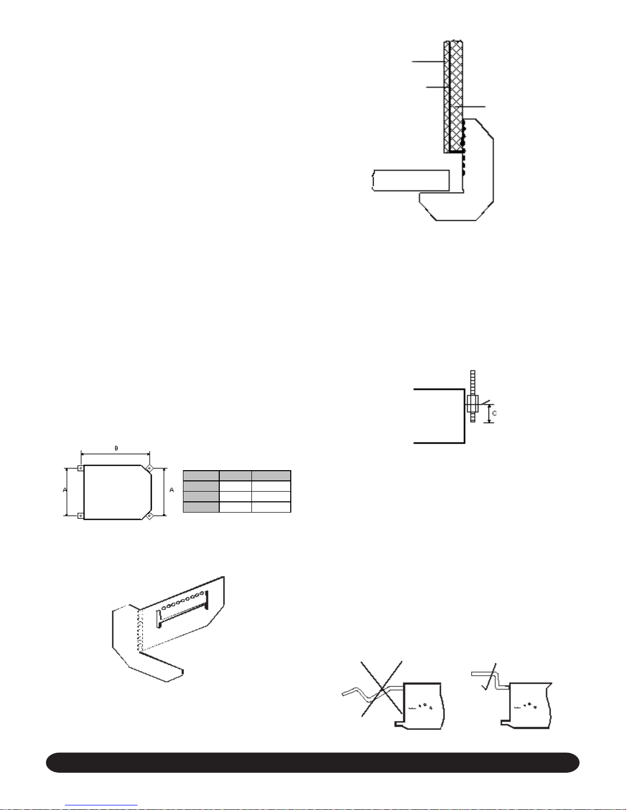
SECTION THROUGH FASCIA
FASCIA BLANKING PIECE
3. Condensate pipework should slope downwards in the
directionofwaterflow withaminimumgradientof(1” per
10’). There must not be any uphill gradients other than
in the first 18” of pipework from the Cassette.
4. When multiple Cassettes are connected to a common
condensate drain, ensure the drain is large enough to
cope with the volume of condensate from several
Cassettes.Itisalsorecommendedtohave an airventin
thecondensate pipework to preventany air locks.
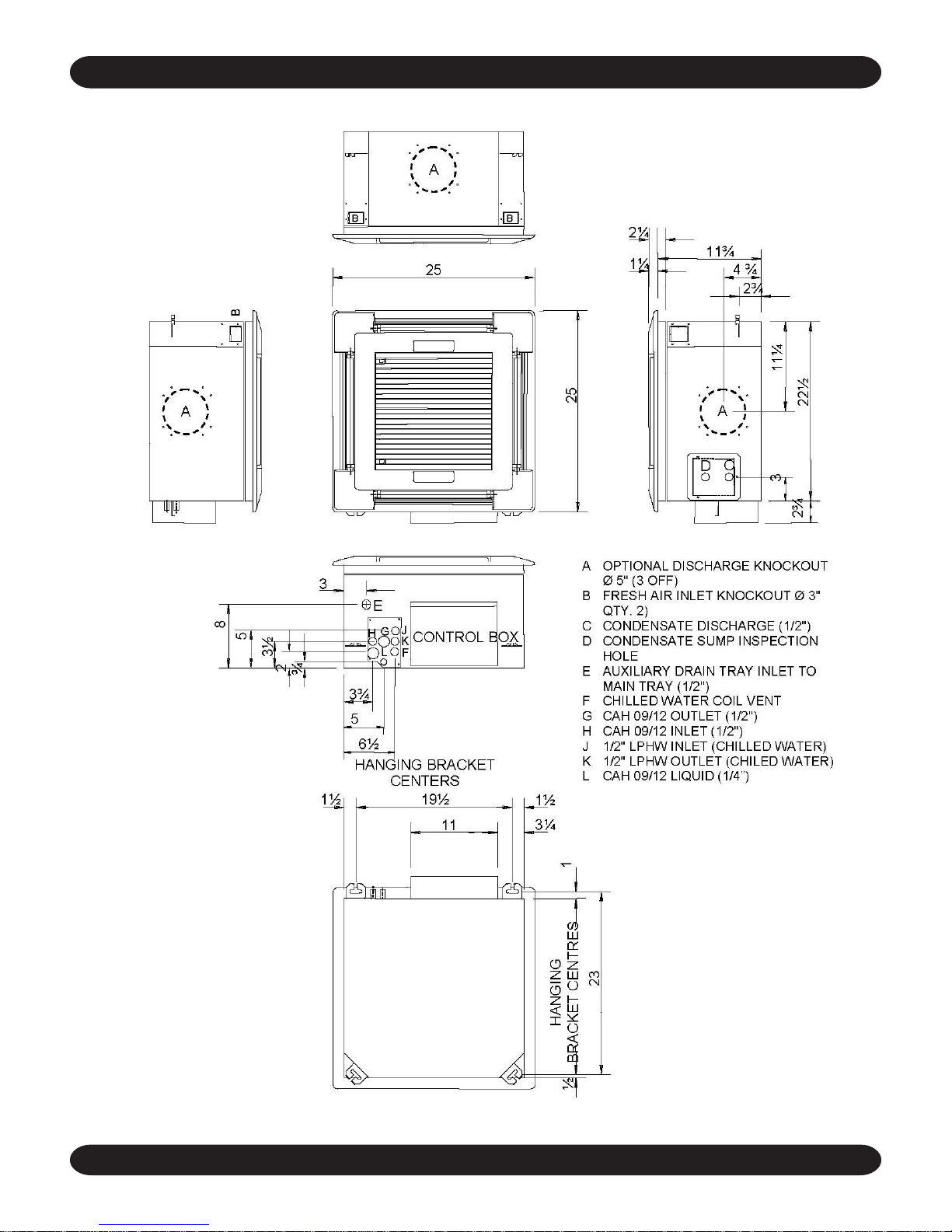
DUCT COLLARS: Branch duct and fresh air duct collars
can be attached to the Cassette chassis by following the
stepsbelow:
1.Refertotherelevant illustrationforyourCassette(pages
6 -7 in this IOM) to become familiarized with knock-out
holelocations.
2. The insulation is pre-cut to aid location and removal of
the relevant section. Rub hand across surface of
insulationto reveal exact location ofknock-out.
3. Remove the metal knockout from the chassis.
4. Attach the duct collar to the chassis using self tapping
screws.
NOTE:Branchductsareroundand5-6”indiameter.
Fresh Air ducts are square and 3” in diameter.
INSULATION: Refrigerant, chilled water and condensate
pipes should be insulated right up to the Cassette chassis.
Chilledwatervalvesmustalsobeinsulatedtopreventsweat-
ing.
ASSEMBLY: Once the services have been connected the
fourfasciamountingboltscanbeunscrewedapproximately
1”from the condensate tray support channels.
ThefasciacannowbeunpackedreadyforfittingtotheCas-
sette chassis. Ensure the black fir tree fasteners holding
thefasciapolystyrene are pushed in firmlyincase of transit
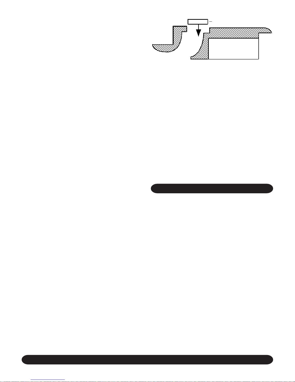
vibration. If a fascia aperture needs blanking off, then take
one of the polystyrene blanking pieces and push it into the
recess in the polystyrene fascia insulation. Fit by removing
the inlet grilles and filters, locating the four fascia mounting
bolts on the chassis through the four keyhole brackets on
the fascia and then sliding the fascia sideways until it locks
into position.
NOTE: Upto two non-adjacent sides can be blanked
off.
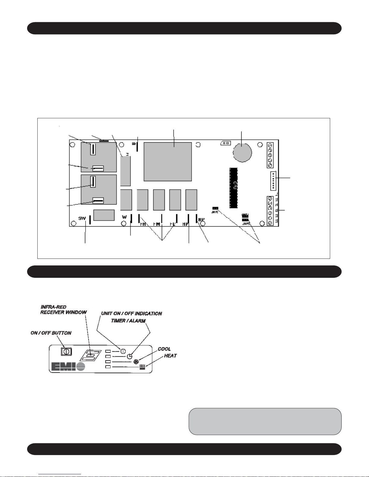
NOTE: On electro-mechanical units, the fascia must
beinstalledwiththeEMIlogo along the same edge of
the unit as the electrical panel. On units fitted with
microprocessorcontrols,orientthefasciawiththedis-
play panel along the same edge of the unit as the
electricalpanel.
Beforetighteningthefasciatotheunit,connectthetwohalves
of the vane motor’s plug and socket connection (where ap-
plicable).
Onmicroprocessorcontrolledunits, ensure that the display
panel cable is routed to the electrical panel and securely
fastenedtoits connectoronthemicroprocessor circuitboard.
(Refer to the unit’s electrical wiring schematic). Take care
to ensure that the connector is connected in the proper ori-
entation and that the wires are not routed such that they
maybecome trapped, cut, broken orchaffed.
Thefasciacannowbetighteneduptothe Cassette chassis
until a good seal is obtained between fascia and chassis.
NOTE: Do not over tighten the bolts. To do so may
cause damage to the fascia.
With filters in place, the inlet grilles can now be fitted to the
fascia to complete the installation.
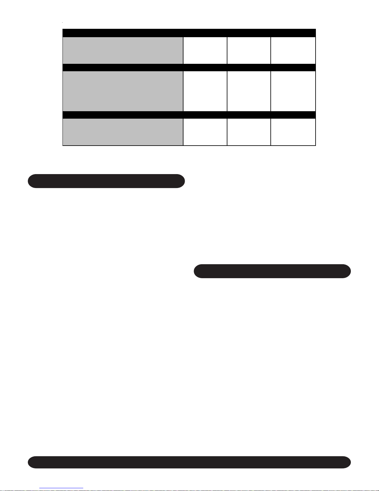
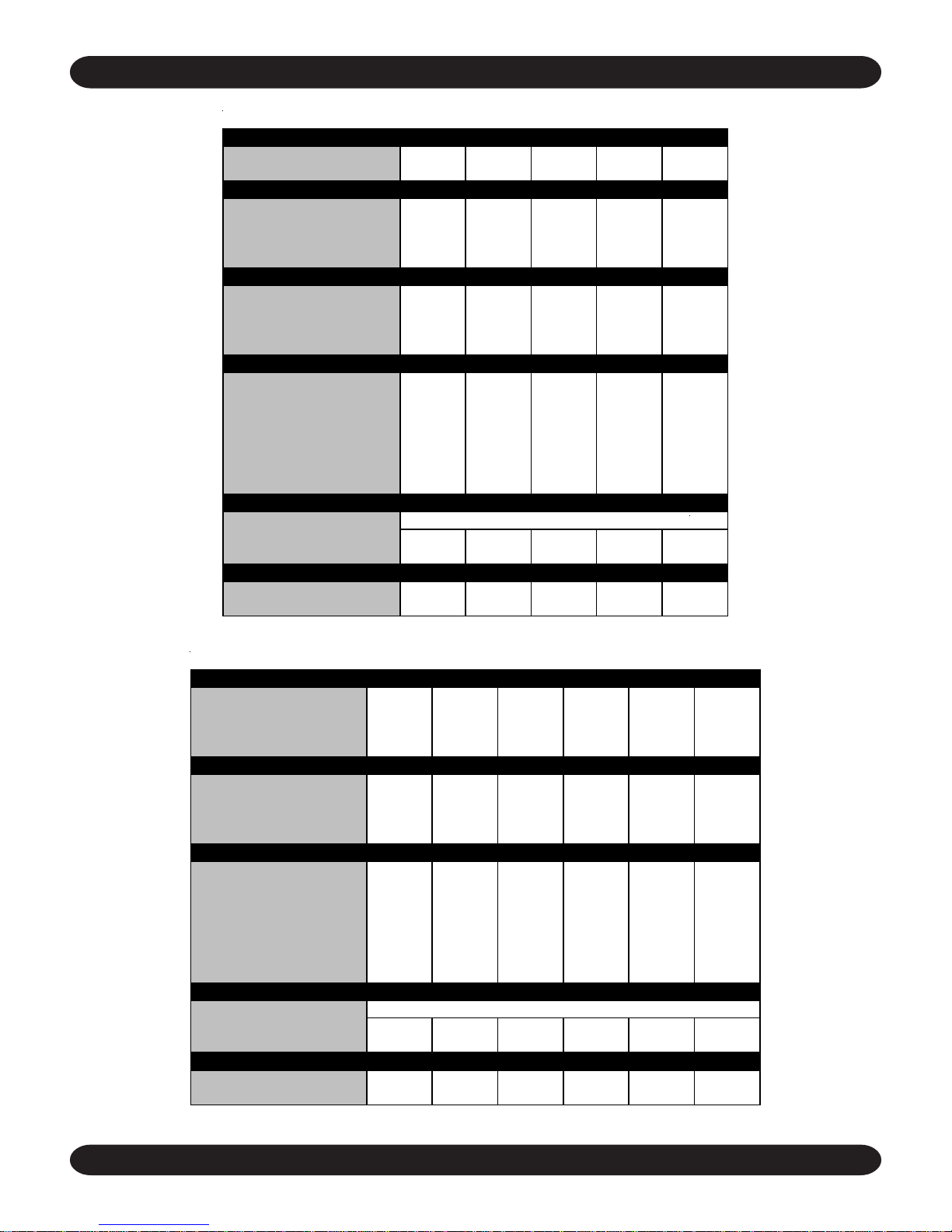
ELECTRICAL DATA
(See Appendix 1 on page 18 for wiring charts and instruc-
tions.)
All power and interconnecting wiring between units should
becarriedouttoconform with local/nationalelectricalcodes.
A fused and dedicated electrical supply of the appropriate
phase,frequencyandvoltage shouldbeinstalledbythecus-
tomer.Itisalsorecommendedthatalocal disconnect switch
be connected within 3’ of the unit. In some areas this may
beacoderequirement.
EMIequipment in its standard form is designed for anelec-
tricalsupplyof208-230V,1Ph,60Hz.When connection to a
115V, 1Ph, 60Hz supply is necessary, a factory mounted
buck boost transformer will be fitted to the unit.
Thewiresshould be capable of carryingthe maximum load
currentundernon-faultconditionsatthestipulated voltages.
Avoid large voltage drops on cable runs, particularly in low
voltage wiring. The correct cable size must be used to en-
sure a voltage drop of less than 1 volt in the control wiring.
Once the refrigeration pipe work is complete, the electrical
supply can be connected by routing the cable through the
appropriatecasingholeandconnectingthesupplyandground
cables to the unit’s power terminals. On the medium and
large cabinets, it will be necessary to remove the insulated
condensate tray support rail, adjacent to the casing hole.

[email protected]ENVIROMASTERINTERNATIONALLLC 5
ELECTRICAL SPECIFICATIONS SMALL MEDIUM LARGE
POWERSUPPLY 230V/1PH/60HZ 230V/1PH/60HZ 230V/1PH/60HZ
FULL LOADAMPS A 0.4 0.6 0.9
MIN. CIRCUIT AMPACITY (MCA) A 0.5 0.75 1.13
REC. FUS
E
A151515
SMALL MEDIUM LARGE
POWERSUPPLY 230V/1PH/60HZ 230V/1PH/60HZ 230V/1PH/60HZ
ELECTRIC HEAT CAPACITY KW 1.5 3.0 5.0
HEATERAMPS A 6.52 13.1 21.7
FULL LOAD AMPS A 7.0 13.7 22.6
MIN. CIRCUIT AMPACITY (MCA) A 8.8 17.1 28.3
REC. FUSE WITH HEAT A 15 20 30
SMALL MEDIUM LARGE
POWERSUPPLY 115V/1PH/60HZ 115V/1PH/60HZ 115V/1PH/60HZ
FULL LOADAMPS A 0.8 1.2 1.8
MIN. CIRCUIT AMPACITY (MCA) A 1.0 1.5 2.26
REC. FUS
E
A151515
(1) STANDARD UNIT FITTED WITH OPTIONAL ELECTRIC HEATING ELEMENTS. AVAILABLE WITH 230V M ODEL UNITS ONLY.
STANDARD UNIT DATA
WITH OPTIONAL ELECTRIC HEAT 1
WITH OPTIONAL BOOST TRANSFORMER 2
(2) STANDARD UNIT FITTED WITHOPTIONAL BOOST TRANSFORMER FOR CONNECTION TO A 115V ELECTRICALSUPPLY.ELECTRIC HEAT
IS NOT AVAILABLE WITHTHISOPTION.
REFRIGERATION SYSTEM (DX UNITS)
PIPE INSTALLATION NOTES
1.Whencooling onlyorheatpumpunitsarebeinginstalled,
it is usually only necessary to insulate the suction line.
However,if the liquid line is subject tohightemperature
or exposed to direct sunlight, this should also be
insulated.
2. Maximum equivalent pipe run should be no more than
100’, with a maximum rise of 35’.
3. Horizontal pipe runs should be slightly inclined, so as
toencourageoiltoflowinthedirectionofthecompressor,
forbetteroil return.
4.Goodrefrigeration practicesmustbeemployed toensure
thecorrectpressure drop and goodoil return.
PRESSURE TESTING: When installation is complete, fill
theCassetteandinterconnectingpipeworkwithdry nitrogen
to a pressure of 150 PSIG. Record the pressure over a pe-
riodoftime(a minimum period of 60 minutesshouldbe suf-
ficient to detect any major leaks, however, ideally 24 hours
should be allowed). If there is any reduction in pressure,
trace the leak and repair before conducting a further pres-
sure test.
EVACUATION: Evacuationshouldbecarried outwithahigh
vacuum pump. The pump should be connected to the high
and low pressure sides of the system via a gauge manifold
fittedwithcompound gauges.Ahigh vacuum gaugeshould
befittedto the system at the furthestpointfromthe vacuum
pump.
Tripleevacuationshouldbeusedtoensurethatallcontami-
nants are removed or at least reduced to significantly low
proportions.
The vacuum pump should be operated until a pressure of
500 microns absolute pressure is reached, at which time
the vacuum pump should be stopped and the vacuum bro-
kenwithoxygenfreenitrogenuntilthepressurerisesabove
zero.
Theaboveoperationshouldberepeatedasecondtime.
The system should then be evacuated a third time but this
time to 100 microns absolute pressure. After stopping the
pump, open the condensing unit’s service valves to break
thevacuum.
START UP PROCEDURES
PRE-START: Once installation is complete it is important
thatthe following pre-startchecks are made.
1.Allpipeworkiscompleteandinsulatedwherenec-
essary.
2.All fans are able to rotate freely.
3.TheCassette and interconnecting pipework have
beenevacuatedcorrectlyandtheCondensingUnit’s
servicevalvesareopen(DXunitsonly).
4.Allelectricalconnections(both power and control)
areproperlyterminated.
5.All condensate drains are installed correctly.
6.Thepower supply is of thecorrectvoltage and fre-
quency.
7.Theunitsareproperlygroundedinaccordancewith
currentelectrical codes.

[email protected]ENVIROMASTERINTERNATIONALLLC 6
START UP SHEET EXAMPLE
ENVIROMASTER INTERNATIONAL LLC
5780SUCCESSDRIVE
ROM E, NY 13440
TEL:1-800-228-9364
FAX:1-800-232-9364
HTTP ://WWW.ENVIROM ASTER.COM
COMMENT:
INITIAL TEST
PRESSURE FINAL TEST
PRESSURE TESTDURATION
GPM
V
V
YES/NO
YES/NO
YES/NO
YES/NO
YES/NO
YES/NO
YES/NO
PSIG
PSIG
ºF
ºF
NOTE: A START UP SHEET FOR EVERY UNIT MUST BE RETURNED TO EMI TO VALIDATE THE WARRANTY.
EMI CASSETTE - CAH/W
,
CAF/4
TO BE COMPLETED IN CONJUNCTION WITH START UP PROCEDUR
E
RETURN ONE COPY TO EM I AND RETAIN ORIGINAL FOR YOUR RECORDS
TE
C
HNI
C
IAN:
M
O
DEL
/S
ERIAL N
O
:
CO
MPANY:
PR
O
JE
C
T: DATE:
1.7 JUMPERS SET CORRECTLY(MICRO ONLY)
2.1 DISABLE COMPRESSOR SIGNAL
1.1 UNITCONDITION SATISFACTORY
1.2 PRESSURE TESTWITH DRYNITROGEN
1.3 DESIGN WATER FLOW AVAILABLE IF
CHILLED WATER UNIT
1.4 VOLTAGE ATOUTDOOR UNIT
2.6 CONDENSATE PUMP OPERATES
2.0 START UP CHECKLIST - INDOOR UNIT
3.0 START UP CHECKLIST - OUTDOOR UNIT (REFER TOTHE RELEVANT OUTDOOR UNITMANUAL AND, IN ADDITION,NOTE THE FOLLOWING:
1.0 PRE START UP CHECKLIST
2.2 ON/OFF WORKS
2.3 INDOOR UNIT:THREE FANS SPEEDS
AVAILABLE (MICRO ONLY)
2.4 VANE SWEEP FUNCTIONS
2.5 TIMER FUNCTIONS OPERATE (MICRO ONLY)
1.5 VOLTAGE ATINDOOR UNIT
1.6 ELECTRICAL CONNECTIONS TIGHT
35. INDOOR AIR TEMPERATURE
3.1 OPERATING PRESSURES
3.2 SUCTION
3.3 DISCHARGE
3.4 AMBIENT TEMPERATURE
8. For microprocessor controlled units, check that
the display panel cable is properly connected to
themicroprocessormaincircuitboardandthatthe
jumper links are correctly set (refer to unit wiring
schematic).If the links are set incorrectly,remove
mainpowerbeforemakinganychanges.
9. For microprocessor controlled units, check that
the battery on the main circuit board is in place
and properly connected. Check also that the bat-
teriesare installed in the infraredunit.
START UP PROCEDURES
Oncetheabovepre-startcheckshavebeencarriedoutsat-
isfactorily, the main start up operation can begin.
IMPORTANT: The jumper links referenced in step
8 must be correctly set before applying mains
power, to ensure correct operation of unit. (micro
unitsonly)

[email protected]ENVIROMASTERINTERNATIONALLLC 7
CAH/W TECHNICAL DATA
REFRIGERATION 09-12 15 18-24 30-36 42-48
NUMBER OFCIRCUITS 1 1 1 1 1
REFRIGERANT TYPE R22 R22 R22 R22 R22
CABINET DIMENSIONS 09-12 15 18-24 30-36 42-48
HEIGHT 10-3/4" 9-1/2" 9-1/2" 11-1/2" 11-1/2"
WIDTH 22-1/2" 32-1/4" 32-1/4" 44-1/2" 44-1/2"
DEPTH 22-1/2" 32-1/4" 32-1/4" 32-1/4" 32-1/4"
WEIGHT 40 LBS. 64 LBS. 64 LBS. 97 LBS. 97 LBS.
FASCIADIMENSIONS 09-12 15 18-24 30-36 42-48
HEIGHT 2-1/4" 3" 3" 3" 3"
WIDTH 25" 37" 37" 49-1/4" 49-1/4"
DEPTH 25" 37" 37" 37" 37"
WEIGHT 5 LBS. 18 LBS. 18 LBS. 21 LBS. 21 LBS.
CONNECTIONS 09-12 15 18-24 30-36 42-48
SUCTION 1/2" 1/2" 5/8"* 3/4" 3/4"**
LIQUID 1/4" 1/4" 3/8" 3/8" 3/8"
CONDENSATE 1/2" 1/2" 1/2" 1/2" 1/2"
BRANCH DUCTDIAMETER 5" 5" 5" 6" 6"
FRESH AIR DUCTDIAMETER 3" 3" 3" 3" 3"
HOTWATER INLET* 1/2" 1/2" 1/2" 1/2" 1/2"
HOTWATEROUTLET* 1/2"1/2"1/2"1/2"1/2"
FILTRATION 09-12 15 18-24 30-36 42-48
TYPE
QUANTITY 12233
ARRESTANCE 0.8 0.8 0.8 0.8 0.8
CONDENSATEPUMP 09-12 15 18-24 30-36 42-48
MAXIMUMHEAD 18" 18" 18" 18" 18"
NOMINAL FLOW RATE (GPM) 0.1 0.1 0.1 0.1 0.1
* 3/4" SUCTION AT EM I CONDENSER. ** 7/8" SUCTION AT EM I CONDENSER.
WIRE FRAMED PERIFRAME
CAF/4 TECHNICAL DATA
CABINET DIMENSIONS 8 12 18 20 33 36
HEIGHT 10-3/4" 9-1/2" 9-1/2" 9-1/2" 11-1/2" 11-1/2"
WIDTH 22-1/2" 32-1/4" 32-1/4" 32-1/4" 44-1/2" 44-1/2"
DEPTH 22-1/2" 32-1/4" 32-1/4" 32-1/4" 32-1/4" 32-1/4"
WEIGHT 40 LBS. 64 LBS. 64 LBS. 64 LBS. 97 LBS. 97 LBS.
FASCIA DIMENSIONS 08 12 18 20 33 36
HEIGHT 2-1/4" 3" 3" 3" 3" 3"
WIDTH 25" 37" 37" 37" 49-1/4" 49-1/4"
DEPTH 25" 37" 37" 37" 37" 37"
WEIGHT 5 LBS. 18 LBS. 18 LBS. 18 LBS. 21 LBS. 21 LBS.
CONNECTIONS 08 12 18 20 33 36
CHILLEDWATERINLET 1/2"3/4"3/4"3/4"3/4"3/4"
CHILLED WATEROUTLET 1/2" 3/4" 3/4" 3/4" 3/4" 3/4"
CONDENSATE 1/2" 1/2" 1/2" 1/2" 1/2" 1/2"
BRANCH DUCTDIAMETER 5" 5" 5" 5" 6" 6"
FRESH AIR DUCTDIAMETER 3" 3" 3" 3" 3" 3"
HOTWATER INLET* 1/2" 1/2" 1/2" 1/2" 1/2" 1/2"
HOTWATEROUTLET* 1/2"1/2"1/2"1/2"1/2"1/2"
FILTRATION 081218203336
TYPE
QUANTITY 122233
ARRESTANCE 0.8 0.8 0.8 0.8 0.8 0.8
CONDENSATE PUMP 08 12 18 20 33 36
MAXIMUMHEAD 18" 18" 18" 18" 18" 18"
NOMINAL FLOW RATE (GPM) 0.1 0.1 0.1 0.1 0.1 0.1
*UNITS FITTED WITH OPTIONAL HOT WATER COIL ONLY
WIRE FRAMED PERIFRAME
EMI CASSETTE MECHANICAL DATA
NOTE: Due to EMI’s ongoing product development program, all designs and specifications are subject to change without notice.

[email protected]ENVIROMASTERINTERNATIONALLLC 8
SMALL CABINET
• CAH 9,000 - 12,000
• CAHW 9,000 ONLY
• CAF 8,000 - 12,000
• CAF4 8,000 ONLY
EMI CASSETTE DIMENSIONS

[email protected]ENVIROMASTERINTERNATIONALLLC 9
MEDIUM CABINET
• CAH 15,000 - 24,000
• CAHW 12,000 - 24,000
• CAF 18,000 - 20,000
• CAF4 12,000 - 20,000
CASSETTE DIMENSIONS (INCHES)
SIZEABCDEF G HJKLMN
MEDIUM 11 37 37 1¾ 32¾ 32¾ 2¾ ½ Ø5 3¼ 9½ ¾ 33¼
LARGE 13 49¼ 37 1¾ 32¾ 45 2¾ ½ Ø6 13¼ 9½ ¾ 45½
EMI CASSETTE DIMENSIONS
LARGE CABINET
• CAH/W 30,000 - 48,000
• CAF/4 33,000 - 36,000

[email protected]ENVIROMASTERINTERNATIONALLLC 10
Theredindicator will be lit when thein-builttime clock func-
tion is activated. To disable the time clock, all start/stop
timesmustbesetto12amviathetransmitter(seeprogram-
ming instructions in this installation manual). The red indi-
cator is also used to diagnose operational alarms.
SELFDIAGNOSTICS:Themicroprocessorcontrollerhasa
built-indiagnosticsfeature so that, inthe event of an alarm,
the nature of the fault can be determined. The red timer/
alarm LED flashes on the fascia in a pre-determined fre-
quencydependingonthefault.Theseare identified below:
1. Red Timer/Alarm flashes once every second - in-
door coil sensor failure, low coil temperature or
condensatehighleveltrip.
2. Red Timer/Alarm flashes once every 5 seconds -
returnairsensorfailure.
Refer to the Troubleshooting section of this
manual for further instruction on dealing with
alarms.
COMPRESSOR
230V AC
TERMI-10A FUSE
COMPRESSOR
HEATOUTPUT
HEATINPUT
230V AC
TERMINAL TRANSFORMER BATTERY
IR RE-
SENSOR
T1 = ROOM SENSOR
T2= DEFROSTINPUT
VANEMOTOROUTPUT
CONDENSATE INDOOR FAN REVERSINGVALVE JUMPER
Theinfraredreceiveris anextensionofthecontrolboardand
is located on the fascia of the unit, connected by a 7 pin
plug and socket.
The green On/Off indicator will remain lit when the unit is
running or will flash if heating or cooling is required but the
compressoranti-cycletimer is delaying compressoropera-
tion.
Yellow indicators will illuminate to show when the unit is in
“cool” or “heat” mode. These indicators will flash when the
batteryon the main circuitboard requires changing.
Thefollowing pages contain a brief overview oftheoptional
cassettemicroprocessorcontrolsystemanditscomponents.
TheInfra-RedRemoteControlmanual is available from the
unitmanufacturer and provides amore comprehensive ex-
planation of the operation and application of the Cassette
microprocessor control system.
The microprocessor controller has built-in software to limit
the number of starts per hour. This operates by having a
minimumperiodoftenminutesbetweenconsecutivestarts.
A four minute delay period between the compressor stop-
ping and starting is also included to allow refrigerant pres-
sures to equalize between high and low sides during the
compressoroffperiod.
IMPORTANT: Beforeapplyingmainpowertotheunit,
please ensure jumper link “JMP2” is in the correct
position. JMP2shouldbeopenforDXNon-HeatPump
or Chilled Water systems and closed for Heat Pump
systems. (A jumper link settings guide can be found
onthe Cassette unit’s wiring schematic).
MICROPROCESSOR CONTROLLER
INFRARED RECEIVER & FASCIA DISPLAY PANEL

[email protected]ENVIROMASTERINTERNATIONALLLC 11
DISPLAYINDICATORS
TRANSMIT INDICATOR
Flashes when system
settings are transmitted.
MODEINDICATOR
Highlights Mode of Operation.
FAN MODE INDICATOR
Highlights Fan Speed.
CLOCK/TIMER DISPLAY
Shows current day, time,
orweeklyprogram Stop/Starttimes.
SETPOINT DISPLAY
Indicated temperature setpoint.
SWINGINDICATOR
Indicates operation of the
motorized air vanes (where fitted).
SLEEPINDICATOR
Indicates when
Sleep mode is selected.
SELECTORBUTTONS
MODEOFOPERATION
Selectsthemodeoptions: Heat, Cool,AutoHeat/
Cool, Dry Coooling, and Fan Only.
FAN
Selects fan speed options: Low, Medium, High,
and Auto.
CLK/TIMER +/-
Selects and adjusts the clock or weekly pro-
gram Stop/Start times.
TEMP +/-
Adjusts temperature setpoint in intervals of 1ºF
beftween 58 - 90ºF.
SLEEP
Selects/Deselects sleep mode. Using the On/
Send button, the temperature setpoint will set
back 2ºF after 1 hour, 4ºF after 2 hours.
SWING
Causes the motorized air vanes to oscillate
when selected (not applicable to all models).
OFF
Switches the unit off (in certain instances the
fan may be subject to a 2 minute run on time to
dissipate residual heat).
ON/SEND
Press this button to switch the unit on and transmit
the system settings. The unit will confirm receipt of
the adjustment by producing a short audible tone.
STANDARD HAND HELD TRANSMITTER: Small,light and practically de-
signed, the hand held transmitter takes 2 AAA batteries that can be easily
fitted by removing the sliding lid on the underside of the transmitter. Please
pay attention to the polarity and correct orientation of the batteries during
fitting.
When using the infrared handheld transmitter, always point the transmitter
headdirectlyat the receiver.UsetheOn/Send button to transmitsettings to
the microprocessor.At the time of transmission the symbol will display
and an audible buzzer will sound if the signal has been correctly received.
After changing any of the settings in the transmitter’s LCD display, the new
settingsmustbetransmittedtotheunit using the On/Send button before the
changes will take effect.
THE INFRARED TRANSMITTER

[email protected]ENVIROMASTERINTERNATIONALLLC 12
SETTING UP THE BUILT-IN
TIME CLOCK
HOW TO SET THE PRESENT TIME
1. Press CLK/Timer: “Clock Set” highlights.
NOTE: Displaywill stop flashing after15 seconds.
2. Select Hour with either (+) or (-). figure will flash.
3. Press (+) or (-) to change hour.
4.PressCLK/Timer to confirm and advance.
5.Repeatsteps3and4forminutesanddayofweek.
6. Press CLK/Timer to confirm.
HOW TO SET COOL, HEAT, OR AUTO MODE
1.PressModebuttonuntildesiredmodeishighlighted.
2. Select temperature with Temp +/- buttons (range
58°Fto90°F).
3. Select desired fan speed with Fan button.
4. Press the On/Send to switch unit on and transmit
system settings.
HOW TO SET DRY MODE
Repeat Steps 1, 2, and 4.
NOTE: During the dry mode the system operates in
cooling only mode and the indoor fan is fixed at low
speed.
HOW TO SET FAN ONLY MODE
Repeat Steps 1, 2, and 4.
NOTE: During the fan only mode only the indoor fan
willoperate, cooling and heating willbe disabled.
HOW TO SET THE WEEKLY PROGRAM
(Monday - Friday)
1. Press CLK/Timer: twice "Program" highlights.
NOTE: Displaywill stop flashing after15 seconds.
2. Select Program 1 by pressing (+) or (-). “Program
1” and “Start Time will flash.
3. Press (+) or (-) to select and change hours.
4. Press CLK/Timer to move to minutes.
5. Repeat steps 3 and 4. “Stop Time” will flash.
6. Repeat steps 3, 4, and 5. “Program 2” and “Start
Time”willflash.
7. Repeat steps 3, 4, and 5. “Send” will flash.
8.PressOn/Send to switch unit onand transmit sys-
tem settings.
NOTE: A small clock symbol will appear in the trans-
mitterdisplay and the red LED indicator on the fascia
displaypanelwillilluminatetoindicatetheweeklypro-
gramis in operation.
HOW TO SET THE WEEKLY PROGRAM (Saturday)
1.PressCLK/Timerthreetimes.“Program” and “SA”
highlight.
NOTE: Display will stop flashing after 15 seconds.
2.Repeatas per Monday - Friday (above).
HOW TO SET THE WEEKLY PROGRAM (Sunday)
1. Press CLK/Timer four times. “Program” and “SU”
highlight.
NOTE: display will stop flashing after 15 seconds.
2.Repeatas per Monday - Friday (above).
IMPORTANT: The built-intime clock provides ON/
OFF functionality. The time clock does not pro-
vide occupied/unoccupied time control. Refer to
the separate Infrared Controller manual for fur-
therdetails.

[email protected]ENVIROMASTERINTERNATIONALLLC 13
IMPORTANT: Asof12/01/04EMIairhandlerswillbemanu-
facturedwithalowVolttransformerinstalled. Atthe same
time,EMIoutdoor condenserswillbemanufactureswith-
outalowVolttransformer. WhenconnectinganEMIevapo-
ratortoanon-EMI condenser, check to ensure thatthereisa
24V control transformer in either in the indoor unit or outdoor
unit. Only one transformer is required. If a transformer is not
present then one should be added to the indoor unit. If both
the indoor unit and outdoor unit contain a transformer, one
must be remover from the system.
CONTROL CIRCUIT CHECKS
(Chilled Water Units)
A thorough pipe work check and pressure test should be
performedbeforethe Cassette controls are setup.
1.Isolate the Cassette from the chilled water supply.
A system electrical check can now be carried out.
2. Switch on the indoor Cassette unit and check that
the fan cycles correctly.
NOTE: In some models there is a two minute fan run on
timetoremoveresidual heat from the Cassette, if theunitis
switchedoffduring the heating mode.
3. On models with microprocessor controls, check
thattheHigh,MediumandLowfanspeedsareop-
eratingcorrectlybychangingthefanspeedviathe
transmitter.
4. On models 15-48, check that the motorized vane
sweep functions correctly by toggling the function
on or off, either via the transmitter (micro units) or
via the toggle switch on the back of the electrical
panellid(electro-mechanicalunits).
5. On micro controlled units, if required, check that
thebuilt-intimerfunctionisprogrammedandoper-
ating correctly. When the timer is activated, the
red LED on the fascia display panel should be lit.
6. Check the operation of the condensate pump by
pouring7-8ouncesofwaterdownthe pump outlet,
switch the unit on, select cooling mode and the
lowestpossibletemperaturesetpointthenobserve
thewaterbeing pumped from the Cassette.
7.Allow chilled water to enter the Cassette and vent
airfrom the unit by opening the 1/4" airbleed. Re-
tighten the bleed screw once all air has been re-
moved.
8. Repeat steps 1-4 above for all Cassettes in the
same systems.
The Cassettes are now ready for the system balance to be
performed.
UNIT START UP - INDOOR UNIT
CONTROL CIRCUIT CHECKS (DX Units)
NOTE: Apply power to the Condensing Unit’s crankcase
heater for 24 hours before start up to boil off any liquid that
may be present in the compressor.
1.After24hours,thecompressor should be isolated
by removing the connection at the “Y” terminal on
theoutdoorunit.Mainpower can nowbeappliedto
the indoor and outdoor units. A system electrical
check can now be carried out.
2. Switch on the indoor Cassette unit and check that
the fan cycles correctly.
NOTE: In some models there is a two minute fan
runon time to removeresidual heat from theCas-
sette, if the unit is switched off during the heating
mode.
3. On models with microprocessor controls, check
thattheHigh,MediumandLowfanspeedsareop-
eratingcorrectlybychangingthefanspeedviathe
transmitter.
4. On models 15-48, check that the motorized vane
sweep functions correctly by toggling the function
on or off, either via the transmitter (micro units) or
via the toggle switch on the back of the electrical
panellid(electro-mechanicalunits).
5. On micro controlled units, if required, check that
thebuilt-intimerfunctionisprogrammedandoper-
ating correctly. When the timer is activated, the
red LED on the fascia display panel should be lit.
6. Check the operation of the condensate pump by
pouring7-8ouncesofwaterdownthe pump outlet,
switch the unit on, select cooling mode and the
lowestpossibletemperaturesetpointthenobserve
thewaterbeing pumped from the Cassette.
7. Where fitted, check the operation of the hot water
valve or the electric heat elements by switching
the system to the heating mode and selecting the
highestpossibletemperature setpoint.
8. Ensure that the Condensing Unit start up proce-
durehas been carried out asdetailed in the corre-
spondinginstallationmanual.
9.Thecompressorsignal“Y”(disconnectedfromthe
outdoor unit in step 1) can now be reconnected
and main power applied to the system.

[email protected]ENVIROMASTERINTERNATIONALLLC 14
TRANSMITTERFAILURE(MICROUNITSONLY).Trynew
batteriesfirst,ifreceiverbleepsontransmitting signal, trans-
mitter is OK. If no response press On/Off button on unit
fascia. If the unit responds to the On/Off button transmitter
is faulty.
MICROPROCESSORFAILURE(MICROUNITSONLY).The
microprocessor is the least likely component to be at fault.
Investigate all other possibilities in every section of this
troubleshooting guide first. Replace the micro only after all
otheravenuesofinvestigationareexhausted.
WATER LEAKING FROM UNIT
(See “Condensate High Level.”)
POSSIBLE CAUSES/REMEDIES
CONDENSATE PLUG LOOSE OR MISSING. Check that
the rubber condensate plug is securely fitted to the under-
sideoftheunit’spolystyrenedriptray. On some models this
is located underneath the fascia support rails on the pump
side of the unit.
UNIT INSTALLED UNEVENLY. Withfasciaremoved,ensure
that the unit chassis is level (at the face) both front to back
and left to right, to ensure correct condensate flow.
CONDENSATEDRAINPIPINGINSTALLEDINCORRECTLY.
Checkthatthesiteinstalledcondensategravitydrain slopes
‘downhill’awayfromtheunit (See installation section of this
manualformoreinformation.)
BLOCKED/KINKEDCONDENSATE PIPE. Checkconden-
satepipeworkforblocks/kinksandclearasnecessary.Check
for a water tight connection between the PVC condensate
outletand the site installed condensate gravity drain.
CONDENSATE PUMPBLOCKED OR FAILED. Clear any
blockages and ensure that power is being applied to the
pump. If the pump still does not run, replace the pump.
FLOAT SWITCH FAILURE. Check that the float switch op-
erates correctly and is properly positioned. Float switch is
normallyclosed, opens on rise of water level.
CONDENSATE HIGH LEVEL
(Red alarm LED on Micro Unit
will flash at one second intervals.)
POSSIBLE CAUSES/REMEDIES
MAXIMUM PUMP LIFT EXCEEDED. Check that the con-
densatepump head is nogreater than 18” (Seeinstallation
sectionofthis manual for more information).
BLOCKED/KINKEDCONDENSATEPIPE.Seesection“Wa-
terLeakingFrom Unit.”
TROUBLESHOOTING SECTION
RED ALARM LED FLASHING AT 1 SECOND
INTERVALS (Microprocessor units only)
POSSIBLE CAUSES/REMEDIES
FAULTY FLOAT SWITCH. See section “Condensate High
Level.”
FAN TRIP. See section “Fans Will Not Run.”
INDOOR COIL SENSOR FAILURE (CONNECTED TO MI-
CRO TERMINAL ‘T3’). After checking the above, use the
unit wiring schematic to isolate the indoor coil sensor and
measurethe resistance. Sensor is50K@72°F type. Check
andreplace if necessary.
RED ALARM LED FLASHING AT 5 SECOND
INTERVALS (Microprocessor units only)
POSSIBLE CAUSES/REMEDIES
RETURNAIRSENSORFAILURE(CONNECTEDTOMICRO
TERMINAL ‘T1’). Use the unit wiring schematic to isolate
thereturnairsensorandmeasure the resistance. Sensor is
50K@72°Ftype. Check and replace if necessary.
UNIT WILL NOT OPERATE
POSSIBLE CAUSES/REMEDIES
NO POWER (MAIN POWER). Check power supply to the
unit. For micro units, check power to the micro and check
theon board micro fuse.
NO 24V CONTROL CIRCUIT POWER. ForDX and chilled
water systems, first check that the condensing unit is
switchedon,thencheckthe24Vfeedfrom the control trans-
former.Ifnotpresent,checktransformerwindings–replace
if necessary.
CONTROL CIRCUIT DISABLED BY UNIT PROTECTION
DEVICE. In some models, particularly electro-mechanical
units, some protection devices (such as freeze-stats, fan
trips,etc)arewiredinlinewiththe24Vcontrolcircuitfeedto
cause the unit to shut down in an alarm condition. Use the
unit’swiringschematictoidentifythesedevicesandinvesti-
gateaccordingly.
INFRAREDRECEIVERFAILURE(MICROUNITS ONLY).If
audiblebleepisheardonsignaltransmissionfromtransmit-
ter and the green LED is lit or flashing, receiver is OK. If
there are no LEDs lit and the unit will not respond to the
transmitter, press the On/Off button on the fascia display
panel. If the unit responds to the On/Off button receiver is
OK. Check transmitter.

[email protected]ENVIROMASTERINTERNATIONALLLC 15
HIGH CONDENSATE LEVELTRIP. Drain the condensate
trayandinvestigate.Seesection“Condensate high Level/”
eratingpressures.Checkfiltercondition.(Seemaintenance
instructionsformoreinformation).
SENSOR FAILURE (MICRO UNITS ONLY). If any of the
sensorsare faulty the microprocessorwill disable the cool-
ingoperation.
OUTDOOR UNIT TRIPPED. Check outdoor unit. refer to
outdoorunittroubleshootingsection.
FAULTY VALVE ACTUATOR (CHILLED WATER UNITS
ONLY). Check cooling signal present at actuator. Check
actuatorbymanuallyopeningthevalve.Replaceactuatorif
necessary.
NO HEATING (HEAT PUMP)
POSSIBLE CAUSES/REMEDIES
INCORRECT MODE SETTING (MICRO UNITS ONLY).
Check that the transmitter MODE is set to Heat or Auto
Mode.
JUMPER LINK SETTINGS INCORRECT (MICRO UNITS
ONLY). Check that JMP2 jumper link header on the micro-
processor is in the “ON” position. Remove power before
makingchanges.
SET POINT TOO LOW. Check the set point on the trans-
mitter or wall mounted thermostat and adjust if necessary.
DEFROST MODE. Unitisdefrostingtheoutdoorcoil.Heat-
ingwillcontinue automatically after defrosting.
COMPRESSOR PROTECTION DELAY (MICRO UNITS
ONLY). Checkthat the green On/OffLedisnot flashing. If it
isflashing wait for amaximum of 10 minutes then re-check
ifheatingis operating.
COMPRESSOR PROTECTION DELAY (ELECTRO-ME-
CHANICAL DX UNITS ONLY). Wait for ten minutes and
thenre-check if cooling isoperating
OUTDOOR UNIT TRIPPED – Refertooutdoorunittrouble-
shootingsection.
INDOORCOILTEMPERATURE TOOHIGH (MICROUNITS
ONLY) – Checkrefrigerant charge by measuringoperating
pressures.Checkfiltercondition(Seemaintenanceinstruc-
tionsformoreinformation).
CONDENSATE PUMP BLOCKED OR FAILED. See sec-
tion “Water Leaking From Unit”
COIL FREEZE UP. Acoilfreezeconditionmayhavecaused
excessive condensate to collect in the drip tray. See sec-
tion“FreezeProtection.”
COIL FREEZE
POSSIBLE CAUSES/REMEDIES
COOLING COIL FREEZE PROTECTION THERMOSTAT
TRIPPED (AUTO-RESET WHEN FREEZE CLEARED).
Freezestatisnormally closed, opens during freeze. Where
fitted, the stat will disable cooling action (sometimes the
entire system) during coil freeze conditions. Use the unit’s
wiringschematicto investigate.
CONDENSING UNIT RUNNING WITH CASSETTE UNIT
SWITCHED OFF (DX SYSTEMS ONLY). Systeminstalled
such that it is possible for condensing unit to run with Cas-
sette unit switched off. Check system wiring and discon-
nect switches.
DIRTYORBLOCKEDAIR FILTER. Clean/replace filtersas
necessary. (See maintenance instructionsformoreinforma-
tion).
SYSTEM HEAD PRESSURE SET TOO LOW. Check con-
densingpressure, installation of lowambient kit may bere-
quired.
LOSS OF REFRIGERANT. Check system for refrigerant
leaksandrepairbeforerecharging.
NO COOLING
POSSIBLE CAUSES/REMEDIES
INCORRECT MODE SETTING (MICRO UNITS ONLY).
Check that the transmitter MODE is set to Cooling orAuto
Mode.
SET POINT TOO HIGH. Check the set point on the trans-
mitter or wall mounted thermostat and adjust if necessary.
COMPRESSOR PROTECTION DELAY (MICRO UNITS
ONLY). CheckthatthegreenOn/OffLEDisnotflashing.Ifit
is flashing, wait for ten minutes then recheck if cooling is
operating (Applies to chilled water units also).
COMPRESSOR PROTECTION DELAY (ELECTRO-ME-
CHANICAL DX UNITS ONLY). Wait for ten minutes and
then recheck if cooling is operating.
DIRTY OR BLOCKED AIR FILTER. See section “Coil
Freeze.”
TROUBLESHOOTING SECTION

[email protected]ENVIROMASTERINTERNATIONALLLC 16
NO HEATING (Electric Heat)
POSSIBLE CAUSES/REMEDIES
INCORRECT MODE SETTING (MICRO UNITS ONLY) –
CheckthatthetransmitterMode is settoHeatorAutoMode.
SET POINT TOO LOW – Check the set point on the trans-
mitter or wall mounted thermostat and adjust if necessary.
OVERHEAT CUT OUT TRIPPED – (See section “Electric
Overheat.”)
Investigatecauseofoverheatcondition.
• Possible low airflow, check filter condition. (See
maintenanceinstructionsformoreinformation).
•Possiblefan failure. Check fans.(Seesection “Fans Will
NotRun”)
Removepowerfromunitandresetmanualoverheatcut-out
byrubbing.DO NOT PRESS!!
Consult EMI technical support for instruction if necessary.
HEATER ELEMENT FAILED – Investigate and replace if
necessary.
FAULTY HEATER RELAY – Check signals to relay and
checkactionofrelaycontacts. Replace relay or PCB if nec-
essary.
NO HEATING (Hot Water)
POSSIBLE CAUSES/REMEDIES
INCORRECT MODE SETTING (MICRO UNITS ONLY) –
Check that the transmitter MODE is set to Heat or Auto
Mode.
SET POINT TOO LOW – Check the set point on the trans-
mitter or wall mounted thermostat and adjust if necessary.
BLOCKEDORDIRTYFILTERSCAUSINGLOWAIRFLOW
– Check filter condition (See maintenance instructions for
moreinformation).
NOHOTWATER/PUMPS FAILED –Checkhotwatersource
and supply to unit.
FAULTY VALVE/ACTUATOR – Check actuator by manu-
allyopeningandclosing valve, replace if faulty.
FAULTY HEATER RELAY – Check signals to relay and
checkactionofrelaycontacts. Replace relay or PCB if nec-
essary.
FANS WILL NOT RUN
POSSIBLE CAUSES/REMEDIES
LOOSE WIRE – Checkall fan wire connections.Use unit’s
electrical schematic to verify that fan is wired correctly.
FAULTYFANCAPACITOR – Checkfancapacitors,replace
if necessary.
FAULTY FAN MOTOR– Checkfanmotorprotectorforopen
circuit, replace if necessary.
ELECTRIC OVERHEAT
The electric heat circuit contains one automatic reset and
onemanualresetoverheatcut-outprotectionswitchforeach
electricheatelementfittedto theunit.Thecut-outsarewired
in line with the mains power flowing in each element and
operateasdescribedbelow.
AUTO CUT-OUT: Iftheauto cut-out trips, theelec-
tric heat is temporarily disabled until the unit tem-
perature falls and causes the overheat cut-out to
automatically reset.
MANUALCUT-OUT: If themanualcut-outtrips,the
electric heat is disabled until the unit temperature
falls and the overheat cut-out is manually reset. It
will typically take five minutes for the unit tempera-
ture to fall sufficiently to allow the cut-out to be re-
set. The cut-out should only be reset by a qualified
andcompetentelectricianandwiththe main power
switchedoff.Ensuretheelementshavecooledsuf-
ficiently.
TROUBLESHOOTING SECTION
! !
WARNING
THISEQUIPMENTCONTAINS LIVEELECTRICALAND
MOVINGPARTS. ISOLATEALLELECTRICALEQUIP-
MENTBEFOREANYMAINTENANCEWORKISCAR-
RIEDOUT!!

[email protected]ENVIROMASTERINTERNATIONALLLC 17
MAINTENANCE
EVERY 3 MONTHS: Checktheairfilterconditionandclean
ifnecessary(see below).
EVERY 6 MONTHS: Sameas3monthspluscleanconden-
satetraywithbiocidesuitableforpolystyreneandcleanfas-
cia.
EVERY 12 MONTHS: Same as 6 months plus check all
electricalconnectionsforsecurity,checkcondensatepump
operation, and check the heating and cooling action to en-
sureproperoperation.
FILTER REMOVAL AND CLEANING
1. Ensure the unit is isolated from the electrical sup-
plyand ensure that the fan(s) has come to a com-
plete stop.
2. Unclip the catches along the edge of each grille
and allow them to hang from the fascia by the
molded plastic hinges located along the opposite
edge.
3.Ifdesired,the grilles can be removed from thefas-
cia completely.
4. The filter can now be easily slid out of the small
plastic retaining clips on the back of each grille.
5.Gentlyvacuumcleanthefiltersonamediumpower
vacuum.
6. Replace filters by reversing steps 2 to 4.
NOTE: EMIrecommendsyoukeepatleastonefull
set of cassette air filters as spares.
FAN REMOVAL
CAUTION:Isolatefrom the electricalsupplybefore
commencing work!!
1. Unclip the grille catches and remove the grille(s)
fromthefascia.
2.Formedium and large-sized units, removetheM6
screwsfromtheblackplastic inlet ring and pull the
inletringdownwardsfromthecondensatetray.For
small units only, remove the fascia by loosening
the four fascia mounting bolts and then slide the
fascia horizontally until it releases from the chas-
sis. Drain the condensate tray by removing the
small black rubber drain plug, catching the con-
densate (if any) in a suitable container. Remove
theselftapping screws securing the twoinsulated
metal condensate tray support channels and pull
the channels away from the condensate tray. Pull
thecondensatetraydownwardsawayfromthechas-
sis.
3.Removetheelectricalpanellidanddisconnectthe
fanconnections from within the electricalpanel.
4.RotatethefanbyhanduntiltwoM6 nuts are visible
through the fan mounting access holes. Remove
the two nuts.
5.Rotatethe fan 90° until the remainingtwonuts are
visibleandremovewhilesupportingthefantopre-
vent it from falling. The fan can now be dropped
downfromthe unit.
CONDENSATE TRAY REMOVAL
1. Unclip the grille catches and remove the grille(s)
fromthefascia.
2.Removethefascia by loosening the fascia mount-
ing bolts and sliding the fascia horizontally until it
releases from the chassis. If unit is micropro-
cessor controlled, remove display panel cable
from within the electrical panel before remov-
ing the fascia.
3.Removeelectricalpanellidbyunscrewingthesingle
self tapper and pull the lid horizontally away from
the control box.
4. On medium and large sized units, disconnect the
main wiring from the incoming terminal block and
disconnectthefanwiresfromtheirconnectionpoints
within the electrical panel. Separate any two part
connectorscoming from the electricalpanel.
5. Drain the condensate tray by removing the small
black rubber drain plug, catching any condensate
in a suitable container.
6. Remove the self tapping screws securing the two
insulatedmetalcondensatetraysupportchannels
and pull the channels away from the condensate
tray. Pull the condensate tray, complete with inlet
ring(onmedium and large sized units only)down-
wardsaway from chassis.
CONDENSATE PUMP REMOVAL
1.Disconnectcondensatepumpandfloatswitchwires
frominsideelectrical panel.
2. Unscrew the three M4 screws holding the pump
inspection plate in place and pull the pump and
mountingbracketawayfromthechassiswhilefeed-
ing the pump wires between condensate tray and
insulation.

[email protected]ENVIROMASTERINTERNATIONALLLC 18
TERMINAL BLOCK INSTRUCTION FOR THE
CONNECTION OF HIGH/LOW VOLTAGE WIRES
When connecting line and/or low voltage wires to
the CAH terminal block(s) a 3/32-screw driver
(thermostat type) is required.
1. Insert the screwdriver into the square hole until
you “hit bottom.” This will open the terminal
block so that it will accept your wire(s).
2. Insert the stripped wire into the oval or round
hole.
3.Remove screwdriver to allow the terminal block
to “clamp down” on the wire(s).
IT IS EXTREMELY IMPORTANT THAT THE WIRE(S)
ARECONNECTEDPROPERLYOTHERWISEARCING
MAY RESULT IN ELECTRICAL DAMAGE OR FIRE!
APPENDIX A - WIRING CHARTS AND INSTRUCTIONS

[email protected]ENVIROMASTERINTERNATIONALLLC 19
1. Cassette Chassis
2. Evaporator Assembly
3. Electric Heater ElementAssembly
4. Condensate Tray
5. Condensate Tray Supports (2)
6. Condensate Pump
7. High Level Switch
8. Condensate Pump Assembly
9. Fan/Motor Assembly
10. Coil/Return Air Sensors
11.Grille
12. Label
13. Air Deflector Vanes (4)
14. Freeze Protection Thermostat (DX Electro-Mechanical Version only)
15. Filter
16. Fascia Assembly
17. Receiver (Microprocessor Version)
18. Terminal Rail, Relays & Timer (Micro & Electro-Mechanical Version)
19. Control Box Lid
20. Control Box
21. PCB Controller (Microprocessor Only)
22. Coil Support Brackets
23. Remote Handset (Microprocessor Only)
SMALL CABINET
• CAH 9,000 - 12,000
• CAHW 9,000 ONLY
• CAF 8,000 - 12,000
• CAF4 8,000 ONLY
APPENDIX B - EXPLODED UNIT DRAWING AND PARTS LIST
18
6
7
22
10
18
19
21 20
14 3
2
9
410
5
16
13
12
15
11
23
17

[email protected]ENVIROMASTERINTERNATIONALLLC 20
1
8
5
7
10
18
19
20
14
3
2
9
4
6
16
13
12
15
11
17
1. Cassette Chassis
2. Evaporator Coil
3. Condensate Tray
4. Condensate Tray Support
5. Condensate Pump
6. High Level Switch
7. Fan & Motor Assembly
8. Fan Inlet Ring
9. Grille
10. Infrared Receiver
11. Vane
12. Vane Motor Assembly
13. Filter
14. Fascia
15. Remote Handset
16. Control Box Lid
17. Control Box PCB
18. Control Box
19. Coil Bracket
20. Expansion Valve
Enviromaster International LLC
5780 Success Drive, Rome, NY 13440
Phone: 1-800-228-9364 / FAX: 1-800-232-9364
Email: emi@enviromaster.com
Web: http://www.enviromaster.com
APPENDIX C - EXPLODED UNIT DRAWING AND PARTS LIST
MEDIUM CABINET
• CAH 15,000 - 24,000
• CAHW 12,000 - 24,000
• CAF 18,000 - 20,000
• CAF4 12,000 - 20,000
LARGE CABINET
• CAH/W 30,000 - 48,000
• CAF/4 33,000 - 36,000
Table of contents
Other EMI Air Conditioner manuals

EMI
EMI MC2 Series s User manual

EMI
EMI E Verter WLHV09 User manual

EMI
EMI S1CG User manual

EMI
EMI enviroair szi ZWHA User manual

EMI
EMI WLHG09 User manual

EMI
EMI enviroair 9000 Btu Instruction manual

EMI
EMI FCP/FHP User manual

EMI
EMI VPAC Instruction manual

EMI
EMI CAHG09 User manual

EMI
EMI UNHG09 User manual
Popular Air Conditioner manuals by other brands

LG
LG AMNH05GD4L0 owner's manual

International comfort products
International comfort products R2A3 GKR Series installation instructions

Cooper & Hunter
Cooper & Hunter Arctic NG Wi-Fi Series owner's manual

Samsung
Samsung MXD-E32K300A installation manual

Alpic Air
Alpic Air AFTMI-100VRDC1A owner's manual

Carrier
Carrier 24ABC6 Product data