Videotec SM82A User manual

OPERATING INSTRUCTIONS
---------------------------------------------------------------------------------------------------------------------------------------------------------
MANUALE D’USO
---------------------------------------------------------------------------------------------------------------------------------------------------------
MANUEL D’INSTRUCTIONS
---------------------------------------------------------------------------------------------------------------------------------------------------------
BEDIENUNGSANWEISUNG
---------------------------------------------------------------------------------------------------------------------------------------------------------
РУКОВОДСТВО ПО ЭКСПЛУАТАЦИИ

US FCC Part 15 Class B Verification Statement
NOTE: This equipment has been tested and found to comply with the limits for a Class B digital
device, pursuant to Part 15 of the FCC Rules. These limits are designed to provide reasonable
protection against harmful interference in a residential installation. This equipment generates, uses
and can radiate radio frequency energy and, if not installed and used in accordance with the
instructions, may cause harmful interference to radio communications. However, there is no
guarantee that interference will not occur in a particular installation. If this equipment does cause
harmful interference to radio or television reception, which can be determined by turning the
equipment off and on, the user is encouraged to try to correct the interference by one or more of the
following measures:
-- Reorient or relocate the receiving antenna.
-- Increase the separation between the equipment and receiver.
-- Connect the equipment into an outlet on a circuit different from that to which the receiver is connected.
-- Consult the dealer or an experienced radio/TV technician for help.

OPERATING
INSTRUCTIONS


Page 1 MNVCSM42A_1511_EN
INDEX
1 INTRODUCTION .......................................................................................................................................................3
1.1 Contents of the package.....................................................................................................................................3
1.2 Contents of this Instruction Manual.....................................................................................................................3
1.3 Typographical conventions .................................................................................................................................3
1.4 Safety rules .........................................................................................................................................................4
1.5 Identification data................................................................................................................................................4
2 SM42A / SM82A MATRIX DESCRIPTION ...............................................................................................................5
2.1 Specifications......................................................................................................................................................5
2.2 Connectable devices...........................................................................................................................................5
3 INSTALLATION.........................................................................................................................................................6
3.1 Preliminary operations ........................................................................................................................................6
3.1.1 Opening the package.....................................................................................................................................................6
3.1.2 Checking the markings ..................................................................................................................................................6
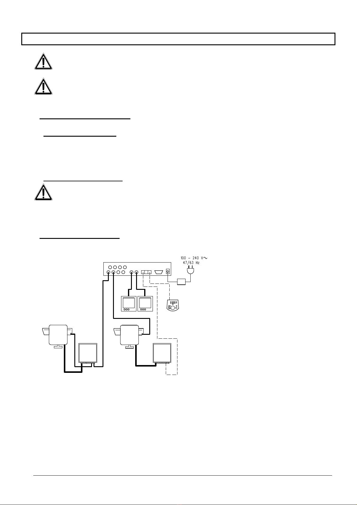
3.2 Installation example ............................................................................................................................................6
3.2.1 Cables............................................................................................................................................................................7
3.3 Switching on and off............................................................................................................................................7
3.4 Configuration.......................................................................................................................................................8
3.4.1 Opening and closing......................................................................................................................................................8
3.4.2 Dip-switches and jumper................................................................................................................................................8
3.4.3 Inserting the load on the AUX line..................................................................................................................................9
3.4.4 Setting 75 Ohm video input termination.........................................................................................................................9
3.5 Connectors and connections.............................................................................................................................10
3.5.1 Connectors on the back of the matrix ..........................................................................................................................10
3.5.2 Pin configuration for DB15...........................................................................................................................................10
3.5.3 Connections for alarm management............................................................................................................................11
3.5.4 Connecting the matrix to the peripherals .....................................................................................................................11
4 MATRIX OPERATING FEATURES........................................................................................................................15
4.1 Video input management..................................................................................................................................15
4.1.1 Automatic switching sequences...................................................................................................................................15
4.1.2 Manual selection..........................................................................................................................................................15
4.1.3 Using the Inc/Dec keys................................................................................................................................................15
4.1.4 Output video dedicated to the VCR .............................................................................................................................15
4.2 Alarms...............................................................................................................................................................16
4.2.1 Alarm contact types .....................................................................................................................................................16
4.2.2 Alarm type....................................................................................................................................................................17
4.2.3 Alarm condition reset...................................................................................................................................................17
4.2.4 Alarm recognition enabling ..........................................................................................................................................17
4.3 Actions on alarms..............................................................................................................................................18
4.3.1 Action to switch videos.................................................................................................................................................18
4.3.2 Action to reposition telemetry.......................................................................................................................................18
4.3.3 Changing the actions...................................................................................................................................................18
4.4 Excluding video inputs ......................................................................................................................................19
4.4.1 How to exclude the video inputs ..................................................................................................................................19
4.5 Auxiliary line......................................................................................................................................................21
4.5.1 Control keyboard configuration....................................................................................................................................21
4.5.2 Video multiplexer control..............................................................................................................................................21
4.5.3 Telemetry receiver control and domes.........................................................................................................................21
4.6 Telemetry protocol ............................................................................................................................................22
4.6.1 Configuring the dome...................................................................................................................................................22
4.6.2 Configuring the switcher/matrix....................................................................................................................................22
4.6.3 Configuring the keyboard.............................................................................................................................................22
4.7 Telemetry transmission on the coaxial cable....................................................................................................23
5 ON SCREEN MENU (OSM) PROGRAMMING.......................................................................................................24

Page 2 MNVCSM42A_1511_EN
5.1 Entering programming.......................................................................................................................................24
5.2 Screens.............................................................................................................................................................24
6 KEYBOARD AND SWITCHING FUNCTIONS........................................................................................................28
7 TROUBLESHOOTING ............................................................................................................................................29
8 MAINTENANCE ......................................................................................................................................................30
9 TECHNICAL SPECIFICATIONS.............................................................................................................................31
The manufacturer assumes no responsibility for possible damages resulting from an improper use of the
devices mentioned in this manual; moreover he reserves the right to change the contents of the present manual
without notice. The documentation contained in this manual has been gathered and examined with great care;
nevertheless the manufacturer can not assume any responsibility resulting from the use of such documentation.
The same is valid for any other person or society involved in the creation and in the production of the present
manual.

Page 3 MNVCSM42A_1511_EN
1 Introduction
1.1 Contents of the package
1 programmable video matrix SM42A / SM82A
1 instruction manual
1 wide range power supply 100 - 240V~ 47/63Hz in, 12V=1A out, including cables
1 DB15 connector
2 telephone boxes RJ-jack
RJ11 telephone cables, 6 pins point-to-point
When the product is delivered make sure the package is intact and has no obvious signs of dropping, scrapes
and scratches. If the package is damaged contact the supplier immediately.
1.2 Contents of this Instruction Manual
This manual describes the video switcher SM42A / SM82A, with its specific procedures for installation,
configuration and use. Before installing and using the video switcher, read this manual carefully,
especially the section concerning the safety rules.
1.3 Typographical conventions
This manual makes use of different graphics symbols, the meaning of which is described as follows:
Hazard of electric shock; disconnect the power supply before proceeding, unless specified otherwise.
Please read the procedure or information shown, and if necessary carry out the instructions in the way.
Failure to carry out the procedure correctly could lead to faulty operation of the system or damage it.
Read carefully to understand system operation.

Page 4 MNVCSM42A_1511_EN
1.4 Safety rules
The video switcher SM42A / SM82A complies with the legislation and standards in force, at the time of
this manual’s publication, with regard to electrical safety, electromagnetic compatibility and general
requirements. Nevertheless, for the safety of the user (installer technician and operator) the following warnings
are specified to ensure completely safe operation:
Connect the system devices to a power supply line corresponding to the one shown on the respective data
plates (see the following section 1.5 Identification data).
The device (and the complete system to which it belongs) must only be installed by a skilled, authorised
technician.
For after-sale service call only authorised staff.
The device should never be opened, but if this becomes necessary the procedures described in this manual
should be followed scrupulously.
Do not unplug the device by pulling the power supply cable.
Before moving or carrying out any technical operations on the device, disconnect the power supply jack: the
device can only be considered off-line when the power supply jack is disconnected and the cables connected
to other devices have been removed.
Do not use extension cables showing signs of wear or aging, since they are extremely hazardous for the user’s safety.
Do not wet the device with any liquid or touch it with wet hands while it is in operation.
Do not leave the device exposed to adverse weather conditions.
Do not use the device in the presence of inflammable substances.
Make sure the device is always resting on a sufficiently large, solid base.
Tampering with the device will invalidate the guarantee.
Keep this manual carefully for future reference.
1.5 Identification data
On the bottom of the video matrix SM42A / SM82A there are two identification plates complying with EC
specifications.
The first plate contains:
Model identification code (Bar code EXT3/9 )
Main supply voltage (Volt)
Frequency (Hertz)
Maximum power consumption (Watt)
The second plate shows the model serial number (Bar code EXT3/9)
Warning! When carrying out installation make sure that the power supply to the matrix corresponds to
the required specifications. Use of inappropriate equipment may be very hazardous for the safety of personnel
and of the system itself.

Page 5 MNVCSM42A_1511_EN
2 SM42A / SM82A matrix description
2.1 Specifications
The SM42A / SM82A matrix is a product for professional use in applications for security and
surveillance. In a security system it is used to control 4/8 input videos on two outputs, using remote keyboards.
The following is a list of its main features:
Video programming
Menu in four languages (Italian, English, French and German)
Different switching sequences for each output video
VCR trigger management
Telemetry control on RS485 auxiliary line and on coaxial cable
Matrix control using 2 serial RS485 lines for remote control devices
Identification tests for each output
Completely configurable alarm input for each input video
Types of alarm reset: manual from keyboard, external, timed, automatic
Relay can be activated by each alarm
Alarm condition warning buzzer
Video signal masking on fixed camera
Local keyboard with 15 keys for complete matrix control.
75 Ohm video input termination removable
Video switching or reposition in case of alarm
Video input exclusion from switching sequence on public monitors
2.2 Connectable devices
Keyboards:
Connect a max. of 2 keyboards using the KEYBOARDS lines:
new series DCJ, DCK, DCTEL, DCBD, DCT, DCIR: used for complete matrix control
Linxs series LXRPK12, LXRPK23, LXRPRC36: only control of video switching
previous series DCMT8, SWC4, SWC8, SWC16, DCS2, DCS3, KEYPLUS: only control of video switching.
An interface is required since communication from the keyboard does not use RS485 (with the exception of
the DCS3 model).
Telemetry receivers:
Control of telemetry receivers using the AUX line:
Videotec receivers DTMRX1, DTRX3, DTRX1, DTRXDC, MICRODEC485, DTMRX2
Dome with protocol Pelco ‘D’
Eneo receivers
Control of telemetry receivers using the video lines (COAX transmission):
Videotec receivers DTRX3 fitted with a DTCOAX board, DTMRX2
Multiplexer videos
Videotec Multiplexer SP16C
Javelin/Hitron Multiplexer
Eneo Multiplexer

Page 6 MNVCSM42A_1511_EN
3 Installation
The following procedures should be carried out before connecting to the power supply, unless indicated
otherwise.
Installation should only be carried out by skilled, authorised technicians. Incorrect connection of the
various peripherals may lead to isolation of the video switcher from the whole system.
3.1 Preliminary operations
3.1.1 Opening the package
If the package has no obvious defect due to dropping or abnormal scrapes and scratches, check the materials it
contains with the list supplied in Section 1.1 Contents of the package.
The installer technician will be responsible for disposing of the packaging material by recycling or, in any case,
according to the current legislation in the country of use.
3.1.2 Checking the markings
Before starting installation, check the identification plates to make sure the supplied material
corresponds with the required specifications, as described in Section 1.5 Identification data. Never, under any
circumstances, make any changes or connections that are not described in this manual: the use of inappropriate
devices may be very hazardous for the safety of people and the system itself.
3.2 Installation example
MATERIAL USED:
Video management:
2 monitors
2 cameras
1 video matrix SM82A
Control keyboard:
1 control keyboard DCTEL
Telemetry management:
1 DTRX3 receiver with
DTCOAX board
1 receiver DTMRX1
1 pan & tilt PTH910P
1 pan & tilt PTH910
SM82A
DTRX3
DTCOA
X
DTMRX1
PTH910P
PTH910
DCTEL

Page 7 MNVCSM42A_1511_EN
3.2.1 Cables
Cable for transmission/reception of commands: unshielded twisted pair with minimum section
0.22 mm² (AWG 24):
a pair for RS485 transmission both for KEYBOARD lines and AUX lines (max. length of connection 1200m.)
a pair for powering the keyboards, which can be remote powered (max. length of connection 700m.)
Cable for DB15 connector: multi-polar cable with minimum section 0.22 mm² (AWG 24)
Video cable: RG59 coaxial cable or equivalent
as well as being used for video transmission it can also be used for transmitting telemetry data (in this case the
max. length of the connection is 350m)
The telephone cable supplied for the AUX line is 1.5 m long: for greater distances use RJ-jack shunt boxes,
following the connection diagrams described in Section 3.5.4 Connecting the matrix to the peripherals.
Multi-polar cable:
every pan & tilt control function is enabled/disabled by a relay inside the receiver.
To determine the final number of wires, follow the instructions below:
7 wires for the pan & tilt movements (230 V~ o 24 V~): right, left, up, down autopan, common, ground (only for
230 V~)
6 wires for reverse polarity lens control (zoom, focus, iris)
4 wires for common wire lens control (zoom, focus, iris)
7 wires for preset management: 5 connected to reference potentiometers, +5 V=and ground
4 wires for the Wiper
3 wires for the Washer
2 wires for each auxiliary used
3 wires for power supply cable
Note: we recommend using different multi-polar cables for low and high voltage functions.
Recommended minimum section: 0.56 mm² (AWG 20) for high voltage wires (pan & tilt, wiper, washer)
0.34 mm² (AWG 22) for low voltage wires (lenses, auxiliaries, preset)
0.75 mm² (AWG 18) for power supply wires to the receiver
3.3 Switching on and off
Before connecting to the power supply:
Make sure the supplied material corresponds to the required specifications by examining the identification
plates as described in section 1.5 Identification Data
Make sure the matrix and other components of the system are closed properly so that there is no possibility
of direct contact with live parts
The matrix and other devices in the system should rest on a large, solid base.
The power supply cables should not get in the way of the installer technician when he is carrying out normal
operations
Make sure the power outlet and extension cables, if used, are sufficient for the system power consumption.
SWITCHING ON: insert the power supply plug in the power outlet and connect the corresponding jack
to the matrix connector labelled 12VDC.
SWITCHING OFF: remove the external power supply plug from the power outlet and disconnect the
jack from the matrix.

Page 8 MNVCSM42A_1511_EN
3.4 Configuration
3.4.1 Opening and closing
Warning! Only skilled, authorised technicians should be allowed to open the matrix.
Disconnect the matrix from the main power supply by disconnecting the jack
Remove the screws on the back of the matrix, behind the top cover
Remove the cover, taking great care not to leave the removed screws or other metal parts inside the matrix
and being very careful with the local keyboard wiring
To close up, carry out the above operations in reverse order, always working with the power supply
disconnected.
3.4.2 Dip-switches and jumper
3.4.2.1 Functions of the dip switches
Inside the SM42A / SM82A matrix there is an 8-way configuration dip switch (SW1):
DIP FUNCTION
DIP 1,2,3,4 Selection of protocol for communication with the keyboards; see section 3.4.2.2
DIP 5 Not used: leave OFF
Dip 6 Not used: leave OFF
Dip 7,8 Not used: leave OFF
Dip Switch SW1
Jumper J5 Video input termination

Page 9 MNVCSM42A_1511_EN
3.4.2.2 Selecting the protocol for communication with the keyboards
Switch off the matrix by disconnecting the power supply jack
Remove the screws fastening down the cover and open the matrix, following the instructions given in section 3.4.1
Find and set the dip-switches according to the table below
Close the cover and fasten it with the screws
Connect the power supply jack to switch the matrix back on.
Note: all changes to the dip-switches are recognised when the matrix is restarted
Dip switch
1 2 3 4 Protocol and baud rate Connected keyboards
OFF
OFF
OFF
OFF
OFF
OFF
OFF
OFF
OFF
OFF
ON
ON
OFF
ON
OFF
ON
Macro, 38400 baud (*)
Macro, 19200 baud
Macro, 9600 baud
Macro, 1200 baud
New series keyboards:
DCJ, DCK, DCTEL, DCBD, DCT, DCIR
OFF
OFF ON
ON OFF
OFF OFF
ON Linxs, 9600 baud
Linxs, 1200 baud Linxs series keyboards:
LXRPK12, LXRPK23, LXRPRC36
OFF
OFF ON
ON ON
ON OFF
ON Videotec switchers, 9600
baud
Videotec switchers, 1200
baud
Previous series keyboards:
SWC4, SWC8, DCMT8 with interface
ON
ON OFF
OFF OFF
OFF OFF
ON Videotec OSM, 9600 baud
Videotec OSM, 1200 baud Previous series keyboards:
DCS2, KEYPLUS, SWC16 with interface
ON OFF ON OFF Videotec SW328, 9600 baud Previous series keyboard: DCS3
ON
ON
ON
ON
ON
OFF
ON
ON
ON
ON
ON
OFF
OFF
ON
ON
ON
OFF
ON
OFF
ON
Invalid configurations -
(*)Default configuration
3.4.3 Inserting the load on the AUX line
To insert/disconnect the 120 Ohm load on the RS485 AUX line, position jumper J5 as shown in the
diagram:
3.4.4 Setting 75 Ohm video input termination
It’s possible to remove the 75 Ohm video input termination putting the corresponding jumper into position B.
Example: all input with 75 Ohm load inserted
Jumper J5 with load connected (position A)
Jumper J5 with load disconnected (position B)

Page 10 MNVCSM42A_1511_EN
3.5 Connectors and connections
3.5.1 Connectors on the back of the matrix
The back of the SM42A / SM82A matrix has:
1 x 15 pin connector for connecting alarm contacts, relay contacts, VCR trigger and external alarm reset
2 x RJ-11 connectors for connecting the keyboards
1 x RJ-11 connector for connecting the telemetry receivers or multiplexers
1 jack connector for the power supply
2 BNC output video connectors
4/8 BNC input video connectors
3.5.2 Pin configuration for DB15
Pin Connection Use
1 Alarm input 1 Alarms
2 Alarm input 2 Alarms
3 Alarm input 3 Alarms
4 Alarm input 4 Alarms
5 Alarm input 5 Alarms
6 Alarm input 6 Alarms
7 Alarm input 7 Alarms
8 Alarm input 8 Alarms
9 GND GND (alarms/ VCR trigger / reset Alarms)
10 NO Relay Peripherals
11 Common Relay Peripherals
12 VCR Trigger Video cassette recorder
13 Reset alarms Reset alarms
14 GND GND (alarms/ VCR trigger / reset Alarms)
15 GND GND (alarms/ VCR trigger / reset Alarms)
Alarms 5-6-7-8 are only available on the SM82A model matrix.
Input video Output
video Aux Line Keyboard
inputs Alarms, VCR trigger
And relè Power supply
Jack

Page 11 MNVCSM42A_1511_EN
3.5.3 Connections for alarm management
See pin configuration table for the DB15 connector.
3.5.3.1 Alarm contacts
WARNING! Do not energise the alarm contacts! The sensors (or the alarm system in use) should supply
a dry contact.
To manage the alarms correctly, be very careful when configuring the alarm parameters at the matrix
programming stage.
3.5.3.2 Auxiliary contact (alarm relay)
The SM42A / SM82A matrix can be used to control an auxiliary contact (relay) that is activated when there is an
alarm, if properly configured at the matrix programming stage. The auxiliary relay contacts are at pins 10 and 11
of the DB15 connector.
3.5.3.3 External reset
The reset impulse is recognised on the falling or rising edge (which can be set at the matrix programming stage)
Pin 13 of the DB15 connector is associated with External Reset of the alarm condition and the ground reference
is pin 14 (or 9 or 15).
3.5.4 Connecting the matrix to the peripherals
3.5.4.1 Control keyboards (Keyboard lines)
All the keyboards specified in section 2.2 Connectable devices and the SM42A / SM82A video matrix can be
connected by telephone cable using the two RJ-11 sockets called KEYBOARDS.
They can be connected directly using the 1.5m cable (supplied with the control keyboards) for short distances,
or, for longer distances, using the RJ-jack wall-mounted boxes (supplied with the control keyboards).
This is not applicable to the previous series keyboards, which require a communication interface because they
do not have RS485 (except for the DCS3 model).
Moreover, the DCTEL and DCBD and Linxs series keyboards can be powered directly by the matrix.
All the keyboards should have transmission rate settings that are compatible with the settings made for the
matrix at the programming stage.
See the respective manuals for configuring the keyboards
Summary:
TYPE OF KEYBOARD CONNECTION MAXIMUM DISTANCE
DCJ, DCK, DCTEL, DCBD, DCT,
DCIR Direct:
RS485 RS485 1200m
Power supply 700m(1)
LXRPK12, LXRPK23,
LXRPRC36 Direct:
RS485 and Power supply RS485 1200m
Power supply 700m
DCMT8, SWC4, SWC8, SWC16,
DCS2, KEYPLUS Connection interface:
RS485 – CURRENT LOOP CURRENT LOOP 1500m
DCS3 Direct:
RS485 RS485 1200m
(1) Only keyboards DCTEL, DCBD

Page 12 MNVCSM42A_1511_EN
Connect the telephone cables as in the following diagram:
Connecting RS 485 KEYBOARD lines
MATRIX RJ-jack 1 RJ-jack 2 KEYBOARD
RS485-A Blue ----------------- White RS485-A
RS485-B Black ----------------- Yellow RS485-B
12 VDC(1) Red ----------------- Green 12 VDC
GND(1) Green ----------------- Red GND
(1) powering the keyboards from the matrix is only possible with the DCTEL and DCBD keyboards and with the
LXRPK12 and LXRPK23 Linxs series keyboards and in any case, up to a maximum distance of 700m
3.5.4.2 Telemetry receivers (AUX line)
All the receivers specified in section 2.2 Connectable devices and the SM42A / SM82A video matrix can be
connected by telephone cable using the RJ-11 socket called AUX.
They can be connected directly using the 1.5m cable (supplied by the manufacturer) for a test or, for longer
distances, using the RJ-jack wall-mounted boxes (supplied by the manufacturer) and referring to the following
table:
RS 485 matrix (AUX line) – Receiver connection
MATRIX RJ-jack 1 RJ-jack 2 RECEIVER
RS485-A White ----------------- Blue RS485-A
RS485-B Yellow ----------------- Black RS485-B
All the receivers should be set up for RS485 communication mode and with a transmission rate that is
compatible with the setting made for the matrix at the programming stage.
See the respective manuals for configuring the receivers.
There are two possible ways of connecting the receivers to the AUX line:
Receivers in cascade (Point-to-point connection)
Receivers on the same line (Multi-point connection)

Page 13 MNVCSM42A_1511_EN
Point to point connection
This type of connection allows the AUX line to be used to control one or more receivers arranged in cascade
(point-to-point type connection). The AUX line of the matrix should have the termination resistance inserted (see
section 3.4.3). Each receiver in turn should have a RS485 line termination resistance inserted. Each receiver
should have a different address. Configure the receivers with RS485 type communication with the same baud
rate and protocol (Videotec or MACRO) as the Matrix AUX line.
Internally, the receivers can regenerate the received signal and send it on along a new communication line to
the next receiver. Each of the three line sections (L1, L2, L3) is considered independent, and connects only two
devices point-to-point, both with the load inserted, for a maximum distance of 1200 metres. The Matrix - R3
receiver distance can therefore be up to 3600 m (1200 m between the Matrix Aux line and receiver R1, 1200 m
between receiver R1 and receiver R2, and a further 1200 m between receiver R2 and receiver R3, for a total of
3600 m).
N.B. For the connection in question (point-to-point), faulty operation of one of the devices will cause faults in the
receivers that follow.
Multipoint connection
This type of connection allows the AUX line to be used to control one or more receivers connected on the same
line (multi-point connection).
All the receivers connected to the same line should use the same communication protocol RS485.
For each line the following should be taken into consideration:
the Aux Matrix line should have the load inserted
only one of the receivers (the one at the end of the line) has the load inserted.
the total length of the line should not exceed 1200 m.
each receiver should have a different address
Receivers R1, R2 should not have the termination resistance inserted. The maximum length of the line, from
end to end (from the matrix AUX line to receiver R3), is 1200 metres.
N.B. For the connection in question (multipoint), a fault in one of the devices does not affect the other receivers.
SM82A
SM82A

Page 14 MNVCSM42A_1511_EN
3.5.4.3 Multiplexer (AUX line)
For the type of Multiplexer to be used, see the following connection tables:
Matrix (AUX line) –Javelin/Hitron Multiplexer RS 485 connection
MATRIX RJ-jack 1 RJ-jack 2 Mux
RS485-A White ----------------- Black RS485-A
RS485-B Yellow ----------------- Green RS485-B
Matrix (AUX line) – SP16C Videotec Multiplexer RS 485 connection
MATRIX RJ-jack 1 RJ-jack 2 Mux
RS485-A White ----------------- Black RS485-A
RS485-B Yellow ----------------- Yellow RS485-B
3.5.4.4 VCR
The Trigger impulse is recognised on the rising or falling edge which can be set at the matrix programming
stage. Connect the VCR input video with output video n°2 of the matrix (VCR dedicated output). For the VCR
trigger on the other hand, refer to the following connection table:
Matrix – VCR connection
Matrix DB15 VCR
Pin 12 – Trigger ------------------------- Trigger pin
Pin 14 – Ground GND ------------------------- Ground pin

Page 15 MNVCSM42A_1511_EN
4 Matrix operating features
4.1 Video input management
4.1.1 Automatic switching sequences
The automatic switching sequences are groups of input videos that are displayed consecutively in the
order and for the length of time defined by the operator. Each switching sequence consists of a minimum of 1
and a maximum of 16 program steps (identified by the letters from A to P).
Each step describes:
the input to be viewed
the viewing time, from 1 to 300 seconds.
There are no restrictions to programming the switching sequence: an input can even be repeated more than
once, as shown in the example below:
Step Input Length
Comment
A 1 2 Input 1 is on view for 2 seconds
B 2 4 Input 2 for 4 seconds
C 5 7 Input 5 for 7 seconds
D - - - Step D is ignored and will be jumped
E 2 5 Input 2 is on view again for 5 seconds
F-P - - - If there are no further program steps, the automatic switching
sequence will resume from step A.
4.1.2 Manual selection
From the keyboard, the operator can directly select a desired input, interrupting the automatic switching
sequence.
A specific input video is always selected with reference to the active monitor: if the keyboard is authorised to
control more than one monitor only the “active monitor” (the last one to be selected) will be involved in the input
video selection.
The local keyboard and the remote DCTEL and DCBD keyboards can be used to control all outputs. Keyboards
DCJ and DCK can be configured to restrict access to a set of output videos dedicated to each operator, so as to
prevent unauthorised personnel from operating at will on all outputs.
4.1.3 Using the Inc/Dec keys
The Inc/Dec keys can be used to block an automatic switching sequence on one input and, where appropriate,
to select the next/previous input video (following the preset order for the switching sequence in progress)
without having to use the numeric keypad to select an input.
4.1.4 Output video dedicated to the VCR
Output video n°2 of matrices SM42A and SM82A is dedicated to the VCR if it is enabled. In this case control of
the VCR channel is only subject to the trigger impulse itself. Any command that may be sent from the keyboard
concerning this channel will therefore be ignored.

Page 16 MNVCSM42A_1511_EN
4.2 Alarms
The matrix provides a DB15 alarm connector, to which 4/8 (depending on the SM42A / SM82A model)
alarm contacts ("alarm input") can be attached, one for each of the input videos of the video device.
When an alarm is activated:
the keyboards able to display the alarm condition can activate a warning buzzer and may also show the
alarm status with a screen message or a flashing LED (this type of operation is determined by the
characteristics and configuration of the individual keyboard).
each output that is enabled for recognition shows the video signal corresponding to the latest recognised
alarm in order of time; if an output is not enabled for recognition of the alarm condition, the alarm will not be
shown on the video
the alarm relay will be closed (auxiliary contact) and in some cases a warning buzzer is activated inside the
matrix, if this is allowed for, by the alarm contact configuration
the text identifying the corresponding input is accompanied by the word “ALARM”.
Alarm status will be stored internally and will be kept, even if there is a temporary interruption to the matrix
power supply. Warning! The alarms must be configured with special care, because a mistake in their settings
could cause faults in operation that are difficult to identify.
4.2.1 Alarm contact types
Each individual alarm contact can be defined:
normally open (N.O.): the alarm condition is recognised when the alarm contact is short circuited to the
common alarm pin
normally closed (N.C.): the alarm condition is recognised when there is a break in the contact between the
alarm and common alarm pin
not used: the alarm contact is ignored.
Warning! Pins that are not connected to any alarm contact should be configured as NOT USED.
See the following example to understand how the alarm contacts function:
Alarms normally open: the contacts are
disconnected from the common alarm
pin. When the contact is closed, alarm
number 3 is recognised.
Alarms normally closed: the contacts are
connected to the common alarm contact
(pin 9). When the connection opened,
alarms 1 and 3 are recognised. This
configuration is also able to recognise as
an alarm a possible break in the cable
connecting the sensor and the matrix.
This manual suits for next models
1
Table of contents
Languages:
Popular Matrix Switcher manuals by other brands

Kramer
Kramer XL 1208V2 Specifications

Foxun
Foxun SX-MX08 operating instructions

Xantech
Xantech XT-HDMI-MX44-4K18G user manual

Guntermann & Drunck
Guntermann & Drunck ControlCenter-Digital-80 installation guide

Matrix Switch Corporation
Matrix Switch Corporation MSC-DE3248 product manual

Cypress
Cypress CPCD-41AR Operation manual