Instrucciones del
Producto
Directives du
Produit
PI-PF 521112 1218 Making PureFlow Crimp Connections (EN ES FR) 2 of 2
Viega LLC • 585 Interlocken Blvd. • Broomfield, CO 80021 • Phone (800) 976-9819 • www.viega.us
Realización de uniones
engarzadas PureFlow®
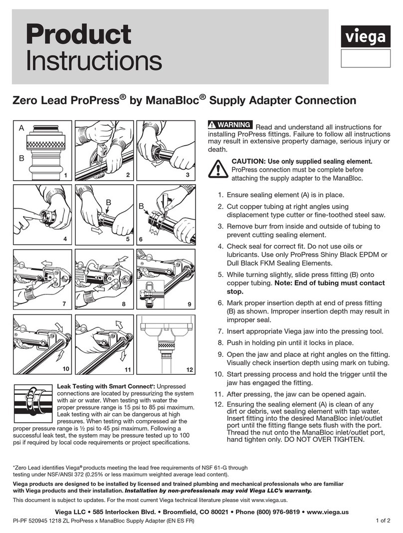
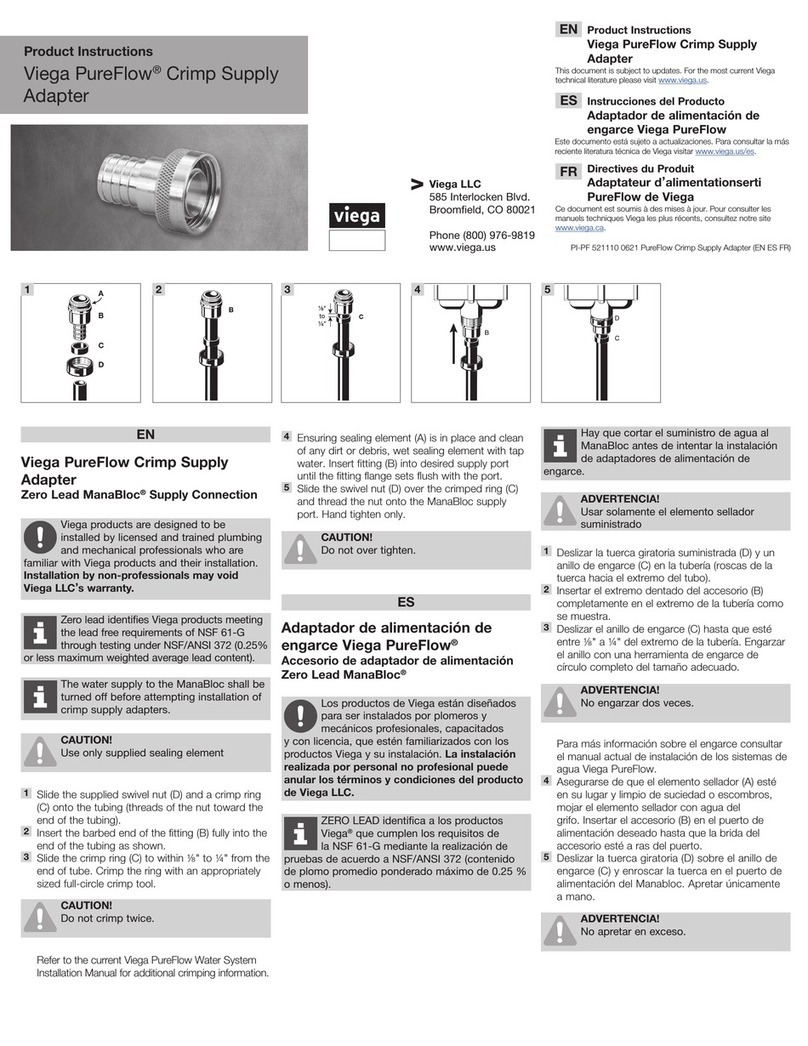
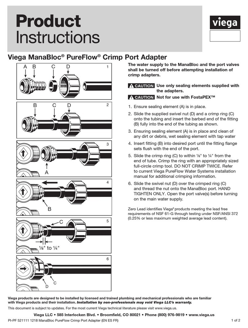
Ver las ilustraciones en la página 1
Réaliser des connexions
serties PureFlow®
Reportez-vous aux images de la page 1
1. La tubería debería cortarse en ángulo recto y
uniformemente, sin rebabas. Los cortes desiguales,
serrados o irregulares producirán uniones no satisfactorias.
2. El diagrama muestra un tubo correctamente cortado en
comparación con un tubo mal cortado.
3. Deslizar el anillo de engarce por la tubería e insertar el
accesorio en el tubo hasta el saliente o el tope del tubo.
4. Posicionar el anillo de ⅛" a ¼" desde el extremo de la
tubería.
5. El anillo debe colocarse recto. Centrar la mordaza de
la herramienta de engarce exactamente sobre el anillo.
Mantener la herramienta a 90° y cerrar los mangos
completamente.
NO ENGARZAR DOS VECES.
6. Al comprobar uniones engarzadas con un calibrador
(galga de PASA/NO PASA), presionar la galga RECTO
HACIA ABAJO sobre el anillo de engarce. No introducir
NUNCA la galga desde el lateral. No tratar de evaluar
el engarce en el área de superposición de la mordaza.
El área de superposición esta indicada por una ligera
desaparición del tratamiento de ennegrecimiento. Un
engarce es aceptable si el elemento "PASA" se ajusta
a la anilla y el elemento "NO PASA" no lo hace. Un
engarce es inaceptable si el elemento "PASA" no se
ajusta a la anilla o si el elemento "NO PASA" sí se ajusta.
Un engarce incorrecto se debe cortar de la tubería y
hay que sustituirlo. Al comprobar uniones de engarce
con un micrómetro o calibrador, utilizar las dimensiones
indicadas en la tabla a continuación.
DIMENSIONES DEL DIÁMETRO DE ENGARCE
Los diámetros exteriores de engarce deberían estar comprendidos
en estas dimensiones al medir con un micrómetro o calibrador.
TAMAÑO DE LA
ANILLA MÍNIMO MÁXIMO
⅜" 0.580" 0.595"
½" 0.700" 0.715"
¾" 0.945" 0.960"
1" 1.175" 1.190"
1. Le tuyau doit être coupé carrément et uniformément pour
éviter les bavures. Les coupes inégales, dentelées ou
irrégulières causeront de mauvaises connexions.
2. Le diagramme illustre la différence entre un tuyau
correctement coupé et un tuyau mal coupé.
3. Faites glisser l'anneau de serrage sur le tuyau et insérez le
raccord dans le tuyau jusqu'à la butée ou l'épaule du tuyau.
4. Placez l'anneau de ⅛ po à ¼ po de l'extrémité du tuyau.
5. L'anneau doit être fixé bien droit. Centrez les mâchoires
de l'outil de sertissage exactement au-dessus de
l'anneau. Gardez l'outil à 90° et fermez les poignées
complètement.
NE PAS SERTIR À DEUX REPRISES.
6. Lors de la vérification des connexions serties à l'aide
d'un étrier (jauge GO / NO GO (accepté/non accepté)),
poussez la jauge TOUT DROIT sur l'anneau serti.
NE JAMAIS faire glisser la jauge à partir du côté.
NE pas essayer d’évaluer le sertissage au niveau
du chevauchement de la mâchoire. La zone de
chevauchement est indiquée par un léger effacement
du traitement de noircissement. Un sertissage est
acceptable si la jauge GO (accepté) s'intègre à l'anneau
et la partie NO GO (non accepté) ne s'intègre pas. Un
sertissage n'est pas acceptable si la jauge NO GO (non
accepté) s'intègre à l'anneau et la partie GO (accepté) ne
s'intègre pas. Un sertissage incorrect doit être découpé
du tuyau et remplacé. Si vous vérifiez les connexions
serties à l'aide d'un micromètre ou d'un étrier, utilisez les
dimensions indiquées dans le tableau ci-dessus.
DIMENSIONS DE DIAMÈTRE DE SERTISSAGE
Les diamètres externes de sertissages doivent respecter ces dimensions
lorsqu'ils sont mesurés à l'aide d'un micromètre ou d'un étrier.
TAILLE DE
L'ANNEAU MINIMUM MAXIMUM
⅜ po 0,580 po 0,595 po
½ po 0,700 po 0,715 po
¾ po 0,945 po 0,960 po
1 po 1,175 po 1,190 po
Este documento está sujeto a actualizaciones. Para consultar la más reciente literatura
técnica de Viega visitar www.viega.us.
Los productos de Viega están diseñados para ser instalados por plomeros y
mecánicos profesionales, capacitados y con licencia, que estén familiarizados
con los productos Viega y su instalación. La instalación realizada por personal no
profesional puede anular los términos y condiciones del producto de Viega LLC.
Les produits Viega sont conçus pour être installés par des plombiers et
mécaniciens professionnels agréés et dûment formés qui en connaissent bien les
méthodes d’utilisation et d’installation. L’installation par des non-professionnels est
susceptible d’entraîner l’annulation des modalités de Viega LLC.
Ce document est soumis à des mises à jour. Pour consulter les manuels techniques Viega les
plus récents, consultez notre site www.viega.us.
La mention LEAD ZERO identie les produits Viega®qui répondent aux exigences des
normes relatives à l’absence de plomb selon l’annexe G de la norme NSF- 61, tels que
testés et homologués selon NSF/ANSI 372 (teneur moyenne pondérée maximale en
plomb de 0,25 % ou moins).
*ZERO LEAD identica a los productos Viega®que cumplen los requisitos de la NSF
61-G mediante la realización de pruebas de acuerdo a NSF/ANSI 372 (contenido de
plomo promedio ponderado máximo de 0.25 % o menos).
