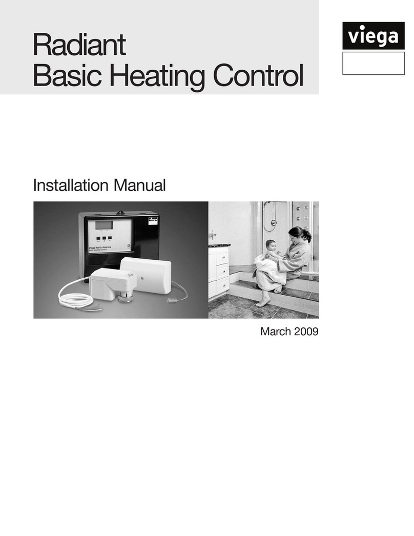
Viega IM-HC 561174 1120 User manual

Installation Manual
Viega Basic Heating Control


3 of 36IM-HC 561174 1120 Basic Heating Control
Table of Contents
Table of Contents
1 About this Document ______________________________________ 5
1.1 Disclaimer ____________________________________________ 5
1.2 Symbols Used _________________________________________ 5
2 Product Information _______________________________________ 6
2.1 Basic Heating Control ___________________________________ 6
3 General Operation _________________________________________ 7
3.1 Using the Control ______________________________________ 7
3.1.1 Item ___________________________________________ 7
3.1.2 Adjust _________________________________________ 7
3.2 Description of Display ___________________________________ 8
3.3 Control Operation ______________________________________ 8
3.4 Control Features _______________________________________ 9
3.4.1 Outdoor Reset __________________________________ 9
3.4.2 Floating Action __________________________________ 9
3.4.3 Warm Weather Shut Down (WWSD) ________________ 9
3.4.4 Exercising ______________________________________ 9
3.5 Temperature Control ___________________________________ 10
3.5.1 System Circulator Pump Operation (Sys Pmp) ______ 10
3.5.2 Mixing Target Temperature (MIX TARGET) __________ 10
3.5.3 Indoor Sensor (Optional) _________________________ 10
3.6 Temperature Control Installer Information _________________ 10
3.6.1 Outdoor Design (OUTDR DSGN) __________________ 10
3.6.2 Room (Room) __________________________________ 11
3.6.3 Mix Design (MIX DSGN) _________________________ 11
3.7 Temperature Control Advanced Information _______________ 11
3.7.1 Mixing Indoor (MIX INDR) ________________________ 11
3.7.2 Mixing Maximum (MIX MAX) ______________________ 11
3.7.3 Warm Weather Shut Down (WWSD) _______________ 11
3.8 Boiler Control _________________________________________ 12
3.8.1 Boiler Operation ________________________________ 12
3.8.2 Boiler Enable __________________________________ 12
4 Installation _______________________________________________ 13
4.1 Mounting and Rough-in ________________________________ 13
4.1.1 Mounting _____________________________________ 14
4.1.2 Rough-In ______________________________________ 15
4.1.3 Installing the Outdoor Sensor_____________________ 16
4.1.4 Installing the Supply Sensor ______________________ 17
4.2 Electrical Connections _________________________________ 17
4.2.1 Powered Input Connection _______________________ 18
4.2.1.1 120V AC Power _________________________ 18
4.2.2 Output Connections ____________________________ 18
4.2.2.1 System Circulator Pump Contacts (Sys Pmp) 18
4.2.2.2 Valve Actuator __________________________ 18

4 of 36 IM-HC 561174 1120 Basic Heating Control
Table of Contents
4.2.3 Sensor and Unpowered Input Connections _________ 19
4.2.3.1 Outdoor Sensor _________________________ 19
4.2.3.2 Supply Sensor __________________________ 19
4.2.3.3 Indoor Sensor ___________________________ 19
4.3 Testing the Wiring _____________________________________ 20
4.3.1 Testing the Sensors _____________________________ 20
4.3.2 Testing the Power Supply ________________________ 20
4.3.3 Testing the Outputs _____________________________ 21
4.3.3.1 System Circulator Pump (Sys Pmp) _________ 21
4.3.3.2 Boiler __________________________________ 21
4.3.4 Connecting the Control __________________________ 21
4.3.4.1 Mixing or Injection Valve Actuator __________ 21
4.4 DIP Switch Settings ___________________________________ 22
4.4.1 Advanced/Installer ______________________________ 22
4.4.2 Boiler Enable 30% - Boiler Enable 10% ____________ 22
4.4.3 Bloc / Station __________________________________ 22
4.5 View Menu Display Settings _____________________________ 23
4.5.1 OUTDR _______________________________________ 23
4.5.2 ROOM ________________________________________ 23
4.5.3 MIX __________________________________________ 23
4.5.4 MIX TARGET __________________________________ 23
4.6 Adjust Menu Display Settings ___________________________ 24
4.6.1 ROOM ________________________________________ 24
4.6.2 OUTDR DSGN _________________________________ 24
4.6.3 MIX DSGN ____________________________________ 24
4.6.4 MIX INDR _____________________________________ 24
4.6.5 MIX MAX ______________________________________ 25
4.6.6 WWSD _______________________________________ 25
4.6.7 UNITS ________________________________________ 25
4.7 Testing the Control ____________________________________ 26
4.7.1 Test Sequence _________________________________ 26
4.7.2 Testing Sensors ________________________________ 26
5 Troubleshooting __________________________________________ 28
5.1 Underheating _________________________________________ 29
5.2 Overheating __________________________________________ 29
5.3 Error Messages _______________________________________ 30
5.3.1 E01 __________________________________________ 30
5.3.2 Shr (OUTDR ___________________________________ 30
5.3.3 OPn (OUTDR)__________________________________ 30
5.3.4 Shr (MIX ______________________________________ 30
5.3.5 OPn (MIX) _____________________________________ 31
5.3.6 Shr (ROOM) ___________________________________ 31
5.3.7 OPn (ROOM) __________________________________ 31
6 Mechanical and Electrical Diagrams _______________________ 32
6.1 Mechanical Schematic _________________________________ 32
6.2 Electrical Schematic ___________________________________ 32
7 Technical Data ___________________________________________ 33
8 Limited Warranty _________________________________________ 34

About this Document
5 of 36
IM-HC 561174 1120 Basic Heating Control
1 About this Document
DANGER!
This symbol warns of possible life-threatening injury.
WARNING!
This symbol warns of possible serious injury.
CAUTION!
This symbol warns of possible injury.
NOTICE!
This symbol warns of possible damage to property.
Notes give additional helpful tips.
1.1 Disclaimer
1.2 Symbols Used
The following symbols may be used within this document:
Viega products are designed to be installed by licensed and
trained plumbing and mechanical professionals who are
familiar with Viega products and their installation. Installation
by non-professionals may void Viega LLC’s warranty.
This document is subject to updates. For the most current
Viega technical literature please visit www.viega.us.

Product Information
6 of 36 IM-HC 561174 1120 Basic Heating Control
The Viega Basic Heating Control is designed to control the supply water
temperature to a hydronic system in order to provide outdoor reset
operation. The Basic Heating Control uses a oating action actuator
mounted on a diverting or mixing valve to regulate the supply water
temperature. The control has a Liquid Crystal Display (LCD) to view
system status and operating information.
Additional functions include:
■ User comfort adjustment to increase or decrease building space
temperature.
■ Advanced settings to ne-tune building requirements.
■ Optional indoor sensor for room air temperature control (Part Number
16016).
■ Test sequence to ensure proper component operation.
■ 120V AC power supply.
■ Powered system circulator pump output.
■ CSA C US certied (approved to applicable UL standards).
2 Product Information
2.1 Basic Heating Control

General Operation
7 of 36
IM-HC 561174 1120 Basic Heating Control
3 General Operation
3.1 Using the Control
The Basic Heating Control uses a Liquid Crystal Display (LCD) as the
method of supplying information. You use the LCD in order to set up and
monitor the operation of your system. The Basic Heating Control has
three push buttons (Item, , ) for selecting and adjusting settings. As
you program your control, record your Adjust Menu settings for future
reference or troubleshooting.
3.1.1 Item
3.1.2 Adjust
The abbreviated name of the selected item will be displayed in the item
eld of the display. To view the next available item, press and release the
Item button. Once you have reached the last available item, pressing and
releasing the Item button will return the display to the rst item.
To make an adjustment to a setting in the control, press and hold
simultaneously for one second, the Item, and buttons. The display
will then show the word ADJUST in the top right corner. Then select the
desired item using the Item button. Finally, use the and/or button to
make the adjustment.
To exit the adjust menu, the control must be left alone for 20 seconds.
When the Item button is pressed and held in the VIEW menu, the control
scrolls through all the control adjust items in both access levels.
Additional information can be gained by observing the Status Field and
Pointers of the LCD. The Status Field will indicate which of the control’s
outputs are currently active. Most symbols in the status eld are only
visible when the VIEW menu is selected.

General Operation
8 of 36 IM-HC 561174 1120 Basic Heating Control
3.2 Description of Display
Circulator
Displays when the system circulator is in operation
Burner
Displays when the boiler relay is turned on
°F, °C
Displays the units of measurement that all of the temperatures are to be
displayed in the control
Pointer
Displays the actuator operation as indicated (open/close)
°F
°C
3.3 Control Operation
When the Basic Heating Control is powered up, the control displays
the control type number in the LCD for two seconds. Next, the software
version is displayed for two seconds. Finally, the control enters into the
normal operating mode.
The Basic Heating Control uses a oating action that can control Viega
diverting or mixing valves to vary the supply water temperature to a
hydronic system. The supply water temperature is based on the outdoor
temperature.
The maximum water temperature setting in the Basic Heating Control
should not be used as a safety high limit control. To protect oors from
high water temperatures in case of main control failure or removal, make
sure high limit is set on mixing device.

General Operation
9 of 36
IM-HC 561174 1120 Basic Heating Control
3.4 Control Features
The Basic Heating Control calculates a mixing supply water temperature
based on the outdoor air temperature. The Basic Heating Control uses a
heating curve and optional indoor temperature feedback from an indoor
sensor in this calculation.
3.4.1 Outdoor Reset
3.4.2 Floating Action
A 24V AC oating action actuator motor is connected directly to the
Basic Heating Control on the COM, OPN, and CLS terminals (7, 8, and 9).
The Basic Heating Control pulses the actuator motor open or closed
to maintain the correct mixed supply water temperature at the supply
sensor. The valve that the actuator is connected to can be either an
injection valve (on the Injection Station), a mixing valve, or a diverting
valve. A visual indication as to whether the control is currently opening or
closing the mixing valve is displayed in the LCD.
3.4.3 Warm Weather Shut Down (WWSD)
The Basic Heating Control monitors the outdoor temperature and shuts
o the heating system seasonally when outdoor temperatures exceed the
Warm Weather Shut Down setting. This reduces energy use during the
summer when the heating system is not needed and saves wear on system
components.
3.4.4 Exercising
The Basic Heating Control has a built-in exercising function. If the system
pump or valve has not been operated at least once every three days, the
control turns on the output for a minimum of 10 seconds. This minimizes
the possibility of a circulator pump or valve seizing during a long period of
inactivity. The Basic Heating Control ensures that the mixing valve operates
over its entire range at least once each exercising period. While the control
is exercising, the Test LED ashes.
The exercising function does not work if power to the
control, circulator, or valve is disconnected.

General Operation
10 of 36 IM-HC 561174 1120 Basic Heating Control
3.5 Temperature Control
An indoor sensor may be used in order to provide indoor temperature
feedback. The indoor sensor is connected to the COM and INDR terminals
(11 and 13). With the indoor sensor connected, the Basic Heating Control is
able to measure the actual room temperature. With this information, the Basic
Heating Control ne-tunes the supply water temperature in the mixing system
to prevent overheating or underheating. To adjust the room temperature for
the mixing zone, use the ROOM setting in the ADJUST menu at the control.
3.6.1 System Circulator Pump Operation (Sys Pmp)
The system circulator pump contact (Sys Pmp, terminal 3) remains closed as long
as the Basic Heating Control is not in Warm Weather Shut Down. During WWSD,
the system Circulator is operated periodically based on the Exercise feature.
3.6.2 Mixing Target Temperature (MIX TARGET)
The MIX TARGET temperature is calculated from the heating curve settings, outdoor
air temperature, and optionally, indoor air temperature. The control displays the
temperature that it is currently trying to maintain as the mixing supply temperature.
3.6.3 Indoor Sensor (Optional)
3.6 Temperature Control Installer Information
3.6.4 Outdoor Design (OUTDR DSGN)
The OUTDR DSGN is the outdoor air temperature that is typically the
coldest temperature of the year where the building is located. This
temperature is used when performing the heat loss calculations for the
building. If a cold outdoor design temperature is selected, the mixing
supply temperature rises gradually as the outdoor temperature drops.
If a warm outdoor design temperature is selected, the mixing supply
temperature rises rapidly as the outdoor temperature drops.

General Operation
11 of 36
IM-HC 561174 1120 Basic Heating Control
The MIX DSGN temperature is the supply water temperature required
to heat the mixing zones when the outdoor air is as cold as the OUTDR
DSGN temperature.
3.6.5 Room (Room)
The ROOM is the desired room temperature for the mixing zones and
it provides a parallel shift of the Heating Curve. The room temperature
desired by the occupants is often dierent from the design indoor
temperature (MIX INDR). If the room temperature is not correct, adjusting
the ROOM setting increases or decreases the amount of heat available to
the building.
3.6.6 Mix Design (MIX DSGN)
3.7 Temperature Control Advanced Information
3.7.1 Mixing Indoor (MIX INDR)
The MIX INDR is the room temperature used in the original heat loss
calculations for the building. This setting establishes the beginning of the
Heating Curve for the mixing zones.
3.7.2 Mixing Maximum (MIX MAX)
The MIX MAX sets the highest water temperature that the control is
allowed to calculate as the MIX TARGET temperature. If the control does
target the MIX MAX setting, and the MIX temperature is near the MIX
MAX, the MAX segment will be displayed in the LCD while either the MIX
TARGET temperature or the MIX temperature is being viewed.
3.7.3 Warm Weather Shut Down (WWSD)
When the outdoor air temperature rises above the WWSD setting, the Basic
Heating Control turns on the WWSD segment in the display. When the
control is in Warm Weather Shut Down, the control does not operate the
heating system (except for exercising - see "3.4.4 Exercising" on page 9).

General Operation
12 of 36 IM-HC 561174 1120 Basic Heating Control
3.8 Boiler Control
3.8.1 Boiler Operation
When the Basic Heating Control determines that boiler operation is required,
the boiler contact terminals (5 and 6) close. While the boiler contact is
closed, the burner segment in the LCD is displayed.
3.8.2 Boiler Enable
Boiler Enable 30% / Boiler Enable 10%)
The Basic Heating Control has a DIP switch that allows for the selection
between a 30% boiler enable and a 10% boiler enable. In the 30% position,
the Basic Heating Control closes the boiler contact when the position of
the mixing valve exceeds 30%. The boiler contact remains closed until
the position of the mixing valve reduces below 15%. This setting would
normally be chosen for low mass boilers (copper n tube, etc.), or systems
with low thermal mass in the loop between the boiler and the mixing valve
(recommended for most Viega applications).
In the 10% position, the Basic Heating Control closes the boiler contact
when the position of the mixing valve exceeds 10%. The boiler contact
remains closed until the position of the mixing valve reduces below 5%.
This setting is normally chosen for high mass boilers (cast iron, steel re
tube, etc.) or systems with large thermal mass in the loop between the boiler
and the mixing valve.

Installation
13 of 36
IM-HC 561174 1120 Basic Heating Control
4 Installation
4.1 Mounting and Rough-in
Check the contents of this package. If any of the contents listed
are missing or damaged, please contact your wholesaler or sales
representative for assistance.
The Basic Heating Control includes: One Basic Heating Control, One
Outdoor Sensor, and One Supply Sensor.
CAUTION!
Improper installation and operation of this control could
result in damage to the equipment and possibly even
personal injury. It is your responsibility to ensure that this
control is safely installed according to all applicable codes
and standards. This electronic control is not intended
for use as a primary limit control. Other controls that are
intended and certied as safety limits must be placed into
the control circuit.
Carefully read the details of the Sequence of Operation to
ensure that you have chosen the proper control for your
application.

Installation
14 of 36 IM-HC 561174 1120 Basic Heating Control
4.1.1 Mounting
Remove the control from its base by pressing down on the release clip in
the wiring chamber and sliding the control upward. The base may then be
mounted by screwing it to a wall or mounting board (screws
not included).
1. Press down at grips on top of cover, then pull out and down to release
cover.
2. Loosen screws at front and pull wiring cover straight out.
3. Remove safety dividers by pulling them straight out.
4. Press release clip on base and slide control upward.
Mounting holes
Release
clip

Installation
15 of 36
IM-HC 561174 1120 Basic Heating Control
5. The control lifts up and away from the base, which is ready for
mounting.
6. Wiring can enter from bottom or back of enclosure. Knockouts allow
wiring to be run in conduit.
4.1.2 Rough-In
All electrical wiring terminates in the control base wiring chamber. The
base has standard 7/8" (22 mm) knockouts, which accept common wiring
hardware and conduit ttings. Before removing the knockouts, check the
wiring diagram and select those sections of the chamber with common
voltages. Do not allow the wiring to cross between sections as the wires
will interfere with safety dividers that should be installed at a later time.
Power must not be applied to any of the wires during the rough-in wiring
stage.
■ Install the Outdoor Sensor and Supply Sensor according to the
instructions on the next two pages and run the wiring back to the control.
■ If an Indoor Sensor (optional) is used, install the sensor according to
the instructions included with it and run the wiring back to the control.
■ Run wire from other system components (circulator pump, boiler,
actuating motor, etc.) to the control.
■ Run wires from the 120V AC power to the control. Use a clean power
source to ensure proper operation. Multi-strand 16 AWG wire is
recommended for all 120V AC wiring due to its superior exibility and
ease of installation into the terminals.

Installation
16 of 36 IM-HC 561174 1120 Basic Heating Control
4.1.3 Installing the Outdoor Sensor
The Outdoor Sensor includes a 10kΩ thermistor that provides an accurate
measurement of the outdoor temperature. The sensor is protected by a
white U.V. resistant plastic enclosure.
Remove the screw and pull the front cover o the sensor enclosure.
The Outdoor Sensor can either be mounted directly onto a wall or a
2" x 4" electrical box. When the sensor is wall mounted, the wiring should
enter through the back or bottom of the enclosure. Do not mount the
sensor with the conduit knockout facing upward as rain could enter the
enclosure and damage the sensor.
In order to prevent heat transmitted through the wall from aecting the
sensor reading, it may be necessary to install an insulating barrier behind
the enclosure.
The Outdoor Sensor should be mounted on a wall that best represents
the heat load on the building (a northern wall for most buildings, and a
southern facing wall for buildings with large south facing glass areas).
The sensor should not be exposed to heat sources such as ventilation or
window openings.
The Outdoor Sensor should be installed at an elevation above the ground
that will prevent accidental damage or tampering, and where it will not be
covered by drifting snow during the winter.
Connect 18 AWG or similar wire to the two terminals provided in the
enclosure and run the wires from the sensor to the control. Do not run
the wires parallel to telephone or power cables. If the sensor wires are
located in an area with strong sources of electromagnetic interference
(EMI), shielded cable or twisted pair should be used or the wires can be
run in a grounded metal conduit. If using shielded cable, the shield wire
should be connected to the COM sensor terminal on the control and not
to earth ground.
Replace the front cover of the sensor enclosure.
When more than one Basic Heating Control is used on a project, the
Outdoor Sensors can be combined into one enclosure by adding the
Multiple Outdoor Sensor module (part number 16020). This mounts in the
Outdoor Sensor enclosure and allows up to four controls to have outdoor
sensors within one enclosure.
Multiple Outdoor Sensor
module mounting location
Wires from
outdoor sensor
to control
terminals
(Com Sen -
Out Sen)
Sensor is built
into the
enclosure

Installation
17 of 36
IM-HC 561174 1120 Basic Heating Control
4.1.4 Installing the Supply Sensor
The Supply Sensor can be strapped directly to the pipe using a plastic
cable tie. Insulation should be placed around the sensor to reduce the
eect of air currents on the sensor measurement.
The Supply Sensor should be placed downstream of a circulator pump
or after an elbow or similar tting. This is especially important if large
diameter pipes are used, as the thermal stratication within the pipe can
result in erroneous sensor readings. Proper sensor location requires that
the uid is thoroughly mixed within the pipe before it reaches the sensor.
When using the Supply Sensor with a Mixing Station, insert the sensor
into the immersion well, see image to the left.
When using the supply sensor with a ProBloc insert the sensor into the
immersion well located in the supply valve body. Connect 18 AWG or
similar wire to the two wires of the sensor and then to the control. Do not
run the wires parallel to telephone or power cables. If the sensor wires
are located in an area with strong sources of electromagnetic interference
(EMI), shielded cable or twisted pair should be used or the wires can be
run in a grounded metal conduit. If using shielded cable, the shield wire
should be connected to the COM sensor terminal on the control and not
to earth ground.
4.2 Electrical Connections
The installer should test to conrm that no voltage is present at any of the
wires. Push the control into the base and slide it down until it snaps rmly
into place
This sensor is designed to mount on a pipe or in a
temperature immersion well.

Installation
18 of 36 IM-HC 561174 1120 Basic Heating Control
4.2.1 Powered Input Connection
Connect the 120V AC power supply to the Power L and Power
N terminals (1 and 2). This connection provides power to the
microprocessor and display of the control. As well, this connection
provides power to the Sys Pmp terminal (3) from the Power L terminal (1).
4.2.1.1 120V AC Power
120V AC
4.2.2 Output Connections
The Sys Pmp output terminal (3) on the Basic Heating Control is a
powered output. When the relay in the Basic Heating Control closes,
120V AC is provided to the Sys Pmp terminal (3) from the Power L
terminal (1). To operate the system circulator, connect one side of the
system circulator circuit to terminal (3) and the second side of the
circulator circuit to the neutral (N) terminal (4).
4.2.2.1 System Circulator Pump Contacts (Sys Pmp)
120V AC
System
Circulator
4.2.2.2 Valve Actuator
Terminals 7, 8, and 9 are powered with 24V AC from the control. There is no
need to provide a separate 24V AC power source for the valve actuator.
R Opn (7) is connected to the open terminal of the actuating motor and R
Cls (8) is connected to the close terminal of the actuating motor. C (9) is
then connected to the common terminal of the actuating motor.
Three Position Actuator for Stations (Part Number 18003)
White wire is common
Green wire is open
Brown wire is close
Mixing Valve Actuator (Part Number 20042)
Blue wire is common
Brown wire is clockwise rotation
Black wire is counter-clockwise rotation
(Whether clockwise is open or close will depend on the orientation of the
Mixing Valve – see valve instructions for details)
Powered Output
Mixing or
Injection Valve
Actuator

Installation
19 of 36
IM-HC 561174 1120 Basic Heating Control
Boiler Contact
The Boiler terminals (5 and 6) are an isolated (dry) output in the Basic
Heating Control. There is no power available on these terminals from
the control. These terminals are to be used as a switch to either make
or break the boiler circuit. When the Basic Heating Control requires the
boiler to re, it closes the contact between terminals 5 and 6.
4.2.3 Sensor and Unpowered Input Connections
Do not apply power to these terminals as this will damage the control.
Connect the two wires from the Outdoor Sensor to the Com and Out
terminals (11 and 12). The Outdoor Sensor is used by the Basic Heating
Control to measure the outdoor air temperature.
4.2.3.1 Outdoor Sensor
Connect the two wires from the Supply Sensor to the Com and Mix
terminals (10 and 11). The Supply Sensor is used by the Basic Heating
Control to measure the supply water temperature downstream of the
diverting or mixing valve.
4.2.3.2 Supply Sensor
If an optional indoor sensor (Part Number 16016) is used, connect the
two wires from the sensor to the Com and Indr terminals (11 and 13) (Part
Number 16016).
4.2.3.3 Indoor Sensor
System
Pump
Supply
Sensor

Installation
20 of 36 IM-HC 561174 1120 Basic Heating Control
4.3 Testing the Wiring
Each terminal block must be unplugged from its header on the control
before power is applied for testing. To remove the terminal block, pull
straight down from the control.
The following tests are to be performed using standard testing practices
and procedures and should only be carried out by properly trained and
experienced persons.
A good quality electrical test meter, capable of reading at least
0 - 300V AC and at least 0 - 2,000,000 Ohms, is essential to properly test
the wiring and sensors.
4.3.1 Testing the Sensors
In order to test the sensors, the actual temperature at each sensor
location must be measured. A good quality digital thermometer with a
surface temperature probe is recommended for ease of use and accuracy.
Where a digital thermometer is not available, a spare sensor can be
strapped alongside the one to be tested and the readings compared. Test
the sensors according to the instructions (see "4.7 Testing the Control" on
page 26
4.3.2 Testing the Power Supply
Make sure exposed wires and bare terminals are not in contact with
other wires or grounded surfaces. Turn on the power and measure the
voltage between the Power L and Power N terminals 1 and 2) using an AC
voltmeter. The reading should be between 108V and 132V AC
108V to 132V AC
Table of contents
Other Viega Control System manuals
Popular Control System manuals by other brands

HydroQuip
HydroQuip WaterPro 622XB Installation & operation manual

Contro l4
Contro l4 Control4 Smart Home System quick start guide

Keyautomation
Keyautomation ALT 4 instruction manual

HydroQuip
HydroQuip PLATINUM PS-9003 Installation & operation guide

Planet
Planet HDVR-1600 user manual

Siemens
Siemens SIMATIC NET SINAUT ST7 System manual