VIERLING ECOTEL C6 User manual

ECOTEL®C6
A TeleControlling Device for Remote Querying, Monitoring and
Controlling over the GSM 900/1800 Mobile Phone Network
Operating Instructions
Edition 1.5
VIERLING Communications GmbH
70411.202/20 - 1.5 – 20051018

VIERLING
Page 2 70411.202/20 - 1.5 – 20051018 – ECOTEL®C6
VIERLING Communications GmbH
Pretzfelder Strasse 21, D-91320 Ebermannstadt
Post Box 11 65, D-91316 Ebermannstadt
Internet: http://www.vierling.de
© 2005 VIERLING Communications GmbH, Ebermannstadt
All rights reserved. Any dissemination, reproduction or processing of
this document or its contents or excerpts from it, regardless of the
procedure used, is prohibited without prior written permission of
VIERLING Communications GmbH.
We reserve the right to make changes without prior notice.
This text was conscientiously prepared. However, VIERLING
Communications GmbH assumes no liability should it nevertheless
contain errors.

VIERLING
ECOTEL®C6 - 70411.202/20 - 1.5 – 20051018 Page 3
Contents
1. SAFETY INFORMATION ........................................................... 5
2. INTRODUCTION ........................................................................ 8
2.1 Applications............................................................................... 8
2.2 Components .............................................................................. 8
2.3 Brief Description ....................................................................... 9
2.3.1 Controlling.......................................................................... 9
2.3.2 Querying ............................................................................. 9
2.3.3 Reporting/ Alarming .......................................................... 9
2.3.4 Counting Impulses ............................................................ 9
2.3.5 Querying the Counter Status.......................................... 10
2.3.6 Configuration ...................................................................10
2.3.7 Internet.............................................................................. 10
3. STARTING-UP ECOTEL®C6 ..................................................11
3.1 SIM Card................................................................................... 11
3.2 PINs ..........................................................................................12
3.2.1 SIM-PIN .............................................................................12
3.2.2 SMS-PIN ............................................................................13
3.3 Reception Conditions/ Antenna Location ............................13
3.4 Inserting the SIM Card into ECOTEL®C6 ............................. 14
3.5 Mounting Options for Housing..............................................15
3.6 Interfaces ................................................................................. 16
3.6.1 Power Supply ................................................................... 16
3.6.2 Relays ...............................................................................17
3.6.3 Digital Inputs .................................................................... 17

VIERLING
Page 4 70411.202/20 - 1.5 – 20050418 – ECOTEL®C6
3.6.4 Analogue Inputs .............................................................. 17
3.6.5 Antenna ............................................................................ 19
3.6.6 Serial Interface (V.24) ...................................................... 19
3.7 Display Elements .................................................................... 20
3.8 Configuration .......................................................................... 21
4. CONFIGURATION PROGRAM ............................................... 22
4.1 Installation ............................................................................... 22
4.2 Program Start.......................................................................... 22
5. TELECONTROLLING .............................................................. 23
5.1 Start Report ............................................................................. 23
5.2 Controlling............................................................................... 23
5.2.1 Controlling with SMS ...................................................... 23
5.2.2 Controlling with Phone Calls ......................................... 24
5.3 Querying .................................................................................. 25
5.3.1 Status Query with SMS ................................................... 25
5.3.2 Status Query with Calls .................................................. 26
5.4 Reporting/ Alarming ............................................................... 27
6. SUMMARY OF COMMANDS .................................................. 28
7. TECHNICAL DATA .................................................................. 29
8. INDEX OF ABBREVIATIONS.................................................. 30

VIERLING
ECOTEL®C6 - 70411.202/20 - 1.5 – 20051018 Page 5
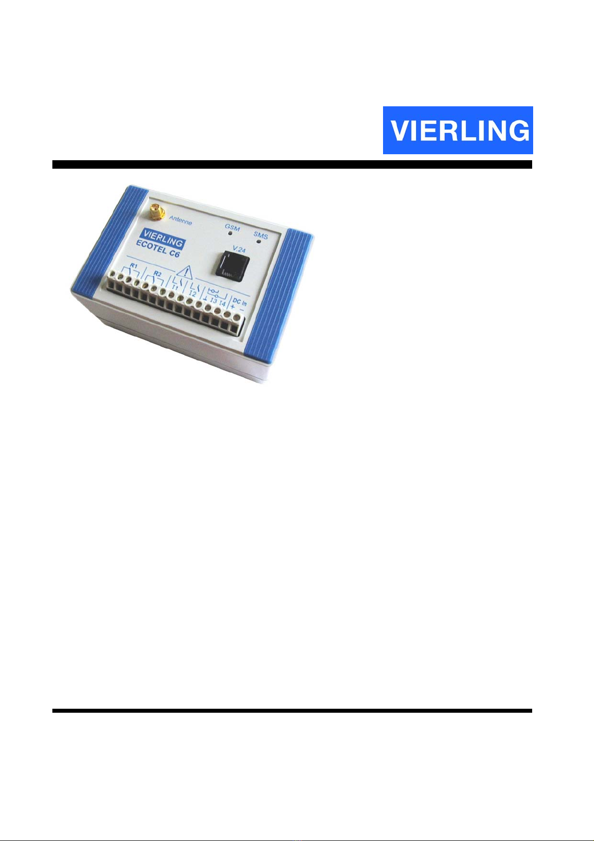
1. Safety Information
General Safety Instructions
This device has been constructed and tested in accord with DIN EN 60950/-
1:2003 VDE 0805, "Institute for Safety in Information Technology". It left the
factory in perfect condition with respect to safety-technology considerations.
In order to maintain this condition and to assure safe operations, the operator
must observe the instructions and heed the warning notes contained in this
manual of operating instructions.
ECOTEL®C6 should only be installed by a professionally trained electrician.
Interfaces are defined as follows in accord with DIN EN 41003 § 4.1.3:
Power Supply max. 30V DC
Inputs I1 ... I4 max. 30V DC
Relays R1, R2 max. 60V DC (42V AC ) 1 A
Maintenance and repairs on an open device may only be undertaken by
professionally qualified personnel.
Liability
Liability for damages are precluded that result from failure to heed the safety
precautions specified. Based upon mandatory liability in accord with legal
regulations governing product liability or other mandatory liability, such liability is
not precluded, for example, in the event of life-endangering injuries, bodily injury
or injury to health, or due to accepting a guarantee or procurement risks, or due
to non-performance of essential contractual obligations.
However, any compensation for damages based upon non-performance of
essential contractual obligations shall be limited to damages that are typical to
such an agreement and which can be anticipated, with the exception of liability
for intent or for the gross negligence of our legally appointed representatives or
vicarious agents or because of injury to life, body or health; or because of the
assumption of a guarantee or of procurement risks. A change in the burden of
proof to the disadvantage of the user is not connected with the regulations
cited.
Transportation
The device should only be transported in its original packaging (protection
against impact and shock).
If the device is brought into an operating location from a cold environment, then
condensation can occur. Before starting operations, the device must be

VIERLING
Page 6 70411.202/20 - 1.5 – 20050418 – ECOTEL®C6
absolutely dry. Thus, an acclimatization period of at least two hours must be
observed.
Setting Up
Protect the device from direct sunlight and heat.
Supply Voltage
If the device is operated on a current source that can supply more than 15 watts,
then the power consumption input of the device should be limited to a maximum
of 15 watts by using appropriate protection (refer to Technical Data section).
If the device runs on a power supply unit that is plugged into the mains, then it
should be installed in the proximity of an electrical outlet that is easily accessible
since the power supply unit also serves as an isolating device from the mains
circuit. Use only those power supply units that meet standards in accord with
EN60950.
If the device is supplied by a battery, then a means of switching-off the current
during emergencies should also be installed.
Connecting Lines
Connecting lines should be laid so that they do not represent a hazard for
pedestrian traffic. During electrical storms, connecting lines should neither be
connected nor disconnected!
Antenna Input
Measures that afford protection against lighting and electrical storms must be
taken before using an external antenna. In particular, the antenna base must be
grounded.
Damages
Should the device be visibly damaged or if it has been subjected to moisture,
operations should be stopped immediately for reasons of safety! In such an
instance, take measures so that other persons are also prevented from
operating the device.
Environmental Conditions
This device may only be operated in a location where the specified
environmental conditions are maintained (refer to "Technical Data"). Assure that
foreign materials such as dust or liquids do not penetrate device openings.

VIERLING
ECOTEL®C6 - 70411.202/20 - 1.5 – 20051018 Page 7
Repairs
Repairs may only be made by qualified personnel. Only replacement parts may
be used that do not violate device safety stipulations.
Always unplug the power supply unit before opening the device!
System Expansion
Install only those system expansions that have been expressly designed for this
device. Using unauthorized expansions can damage the device or may violate
safety specifications and regulations pertaining to radio interference
suppression.
Cleaning
Always unplug the power supply unit before cleaning the device.
When cleaning, do not use powdered detergents or agents aggressive to
synthetic materials. Do not allow moisture to penetrate the device. A dry cloth is
sufficient to clean the housing surface. If required, a damp cloth may be used
that has been dipped in water with mild dishwashing liquid and wrung out.
Inserting the SIM Card
Be certain to follow the instructions in the user manual under section 3.4 in order
to avoid damaging ECOTEL®C6 as a result of static discharges.
Messaging with SMS
When messaging (SMS/Fax/E-Mail), ECOTEL®C6 dispatches an SMS over the
GSM network. However, GSM mobile network providers do not offer a
guarantee that SMSs will arrive at their destination within a given time period.
Therefore, messaging delays may occur or, in exceptional cases, a message
may not arrive at its destination.

VIERLING
Page 8 70411.202/20 - 1.5 – 20050418 – ECOTEL®C6
2. Introduction
ATTENTION
Before inserting the SIM card deactivate the PIN of the SIM
card or use the specified PIN. See also page 31.
2.1 Applications
ECOTEL®C6 can be used to
• Control devices and systems
• Query conditions and status quo
• Report specified events (alarming)
• Count impulses
• Query the status of impulse-counters
over the GSM Mobile Phone Network GSM900/1800 by using SMSs or
telephone calls.
2.2 Components
The ECOTEL®C6 product package consists of the following:
• ECOTEL®C6 device
• 2 gray covering panels with 4 rubber feet
• 2 blue covering panels
• CD with Windows configuration program ECOTEL®C6 config
• Operating instructions
• Serial cable for configuration
• Short antenna
• SMA-FME antenna adapter 1)
• Power supply unit 1)
• DIN rail-assembly footing, including 4 screws 1)
1) Not included with ECOTEL®C6(a) (is equal to CONRAD model)

VIERLING
ECOTEL®C6 - 70411.202/20 - 1.5 – 20051018 Page 9
In order to operate ECOTEL®C6, you will require:
• SIM card (card agreement or prepaid cards)
• GSM external antenna (only for conditions of poor reception).
• Laptop with RS232 serial interface for configuration purposes
• Electrical supply unit for ECOTEL®C6 (a)
The following is available as an accessory:
• GSM Dual Band External Antenna GSM900/1800 (including
antenna cable) for conditions of poor reception.
2.3 Brief Description
2.3.1 Controlling
ECOTEL®C6 has two relay contacts (change-over contact) which can
be remotely controlled with a mobile phone or over the Internet.
2.3.2 Querying
ECOTEL®C6 has two digital and two analogue inputs. Their respective
input conditions can be remotely queried with a mobile phone or over
the Internet.
2.3.3 Reporting/ Alarming
ECOTEL®C6 can be configured so that when a specified condition
occurs, it automatically sends an SMS to the inputs. You are then
informed (or alarmed) with respect to the current input condition with an
SMS, fax or e-mail.
2.3.4 Counting Impulses
ECOTEL®C6 has one digital input that can function as an impulse-
counter-input. Each arriving impulse increases the ECOTEL®C6

VIERLING
Page 10 70411.202/20 - 1.5 – 20050418 – ECOTEL®C6
internal counter by 1. After a power failure the counter starts with 0. The
impulses are counted from 0 to 4.000.000.
2.3.5 Querying the Counter Status
The counter status of ECOTEL®C6 can be remotely queried with a
mobile phone or via Internet.
2.3.6 Configuration
ECOTEL®C6 is easily configured over the serial interface by using the
Windows program ECOTEL®C6 config, which is included in the product
package. Remote configuration is also possible using a mobile phone
and SMSs.
2.3.7 Internet
It is also possible to control and query ECOTEL®C6 via Internet by
sending and receiving SMSs from an internet service provider. Several
internet pages provide this feature.

VIERLING
ECOTEL®C6 - 70411.202/20 - 1.5 – 20051018 Page 11
3. Starting-Up ECOTEL®C6
The following points must be clarified when starting operations for the
first time:
• SIM card (card agreement or prepaid card)
• PIN for the SIM card
• Receiving conditions/ antenna location
• Installation at the assembly location
• Power supply
• Configuration with ECOTEL®C6 config program
• Connection of relays and inputs
3.1 SIM Card
ECOTEL®C6 contains a GSM module similar to a mobile phone, and it
also requires a SIM card. SIM cards can be used for both the GSM900
and the GSM1800 mobile phone networks.
If SMSs are frequently sent, then a favorable alternative is to use
mobile phone card agreements with monthly basic rental charges, low
SMS costs and generally unlimited validity.
If SMSs are sent less frequently, then the use of a prepaid card
without basic rental charges is recommended. In this case, SMS costs
are somewhat higher and validity is usually limited to either 6 or 12
months. After expiration of validity, the prepaid card must be
replenished. Usually, this requires removing the card from ECOTEL®C6
in order to replenish it by using a mobile phone. Prepaid cards can be
remotely reloaded. Information is available from the internet home page
of your provider.
NOTE:
Select a suitable SIM card for your particular needs.
Scrutinize the various costs for SMS, SMS to fax and SMS
to e-mail.

VIERLING
Page 12 70411.202/20 - 1.5 – 20050418 – ECOTEL®C6
3.2 PINs
When operating ECOTEL®C6, there are two different PINs. The first
PIN secures access to the SIM card (SIM-PIN) while the second PIN
protects ECOTEL®C6 from being used by unauthorized persons (SMS-
PIN).
3.2.1 SIM-PIN
Protect your SIM card with a PIN. The SIM-PIN for your ECOTEL®C6
can not be freely selected. The PIN to be used is printed on the last
page of these operating instructions. Insert the SIM card to be used for
ECOTEL®C6 into a mobile phone and modify the PIN in accord with
information provided. Details regarding activating and modifying a PIN
can be found in your mobile phone operating instructions. Should you
choose not to secure your SIM card, then the PIN function should be
deactivated. Details in this respect are also available in your mobile
phone operating instructions.
NOTE:
For some providers (SIM cards), the PIN function can not be
deactivated.
ATTENTION
The specified SIM-PIN should be correctly entered. After
three attempts to log-in with an incorrect PIN, the SIM card
will be blocked. A super-PIN is then required in order to
reactivate the SIM card.

VIERLING
ECOTEL®C6 - 70411.202/20 - 1.5 – 20051018 Page 13
3.2.2 SMS-PIN
The SMS-PIN prevents unauthorized use of ECOTEL®C6 over SMS.
When the PIN identification function is activated, a PIN is required for
controlling outputs and querying inputs, and it must appear at the
beginning of every SMS sent to ECOTEL®C6. Refer to section 5
TeleControlling.
3.3 Reception Conditions/ Antenna Location
ECOTEL®C6 depends upon adequate receiving conditions in order to
send and receive SMSs. Prior to installation, good estimates can be
made with a mobile phone. First, insert the SIM card for ECOTEL®C6 in
a mobile phone and then check-out reception conditions at several
different points. If the mobile phone indicates adequate field strength,
this is generally sufficient for ECOTEL®C6 receiving conditions as well.
ATTENTION
Measures that afford protection against lighting and electrical
storms must be taken before using an external antenna. In
particular, the antenna base must be grounded.
NOTE:
Receiving conditions among the various mobile phone
networks are usually different.
Exact receiving conditions can be determined with ECOTEL®C6 and
the ECOTEL®C6 config configuration program.
• Insert SIM card into ECOTEL®C6
• Connect short antenna
• Connect power supply
• Connect ECOTEL®C6 to laptop
• Install Windows ECOTEL®C6 config program and start
• Menu Status

VIERLING
Page 14 70411.202/20 - 1.5 – 20050418 – ECOTEL®C6
The short antenna can be used if it is adequate for reception conditions
prevailing at the assembly location. Minimum reception field strength
app. –80 dBm.
Should reception conditions be insufficient, a GSM antenna will be
required at an appropriate location. The antenna is then to be
connected to ECOTEL®C6 using an antenna cable.
NOTE:
Suitable antennas and antenna cable are available as
accessories
3.4 Inserting the SIM Card into ECOTEL®C6
The power supply should be disconnected and section 3.2.1 SIM-PIN
should be read before inserting a SIM card. Open the ECOTEL®C6
housing and insert the SIM card into the SIM card holder provided. In
the process, touch the module plug as illustrated to discharge static
electricity and thus avoid damaging the unit. In order to arrest the SIM
card, shove the lid of the SIM card holder forwards.

VIERLING
ECOTEL®C6 - 70411.202/20 - 1.5 – 20051018 Page 15
Illustration 1: Inserting the SIM card into ECOTEL®C6
3.5 Mounting Options for Housing
The universal ECOTEL®C6 housing offers three mounting options:
• Desk-top housing (rubber feet)
• Wall-mounted housing (screws)
• Control cubicle (DIN rail-assembly)
Mount the housing according to your requirements.

VIERLING
Page 16 70411.202/20 - 1.5 – 20050418 – ECOTEL®C6
Illustration 2: Mounting the ECOTEL®C6 Housing
3.6 Interfaces
ATTENTION
Observe VDE regulations when connecting relay contacts
(R1, R2) and inputs (I1 to I4).
Connected voltages may not exceed 60V DC / 42 V AC
(SELV-Electrical Circuit).
3.6.1 Power Supply
ECOTEL®C6 can utilize an existing, suitable power supply, or the
power supply unit included in the product package may be used. In case

VIERLING
ECOTEL®C6 - 70411.202/20 - 1.5 – 20051018 Page 17
the original power supply unit is not being used, the power supply itself
must be fuse-protected. Refer to section 7 Technical Data. The DC In
input is protected against reversed connections.
3.6.2 Relays
ECOTEL®C6 has two relays, R1 and R2, each with a change-over
contact. Maximum current load for the contacts are:
• 2 A for 30 V turn-on voltage
• 1 A for 60 V turn-on voltage
3.6.3 Digital Inputs
ECOTEL®C6 has two digital inputs, I1 and I2, for connecting potential-
free contacts (make-contact or break-contact). When making or
breaking contact, ECOTEL®C6 sends an SMS and thus informs/ alarms
you of the current status of the inputs by using an SMS, a fax or an e-
mail. In the last two instances, the SMS is converted into a fax or an e-
mail (SMS to fax, SMS to e-mail).
Input I1 can also be configured as an impulse counter. In this event,
switching-impulses arriving at the I1 input are counted in an internal
counter.
Refer to section 5.3 Querying regarding the querying of input conditions
or the counter status.
3.6.4 Analogue Inputs
ECOTEL®C6 has two analogue inputs (I3 and I4) which emit a
measuring voltage and are to be connected to sensors. When
overshooting or undershooting a given voltage threshold, ECOTEL®C6
sends an SMS informing you of current input status via SMS, fax or e-
mail. In the last two instances, the SMS is converted into a fax or an e-
mail (SMS to Fax, SMS to e-mail). The input voltage range (measuring
voltage) is:
• Input I3: 0 to 12.75 volts Input I4: 0 to 25.50 volts.

VIERLING
Page 18 70411.202/20 - 1.5 – 20050418 – ECOTEL®C6
3.6.4.1 Hysteresis
In order to avoid multiple reports resulting from small voltage-deviations
about the threshold value, high and low threshold boundaries have been
established.
Mode of operation when overshooting the threshold value: If the input
voltage overshoots the lower boundary and then the threshold value,
then ECOTEL®C6 sends a report.
Illustration 3: Threshold value and lower boundary value
Mode of operation when undershooting the threshold value: If the input
voltage undershoots the upper boundary and then the threshold value,
then ECOTEL®C6 sends a report.
I
nput
V
o
l
tage
Time
Report Report
Threshold Value
Lower Boundary
Value

VIERLING
ECOTEL®C6 - 70411.202/20 - 1.5 – 20051018 Page 19
Illustration 4: Threshold value and upper boundary value
Refer to section 5.3 Querying for information about querying input
conditions.
3.6.5 Antenna
The antenna interface has been designed to directly connect the short
antenna. If reception conditions are adequate, this antenna can be
used. Where reception conditions are poor, an antenna must be
connected using an antenna cable and adapter.
3.6.6 Serial Interface (V.24)
Serial interface V.24 is to be used when configuring ECOTEL®C6. It is
to be connected to the laptop/ PC COM-Port by using the serial cable
included in the product package accessories.
I
nput
V
o
l
tage
Time
Report Report
Threshold Value
Upper Boundary
Value

VIERLING
Page 20 70411.202/20 - 1.5 – 20050418 – ECOTEL®C6
3.7 Display Elements
ECOTEL®C6 has two light-emitting diodes that are used to indicate
current operating conditions.
The green "GSM" LED shows the operating condition.
"GSM" LED Significance
Off No power supply
On SIM card not yet logged-in to the mobile phone network
Blinking SIM card logged-in to the mobile phone network
Table 1: Significance of the green "GSM" LED
The red "SMS" LED indicates sending or receiving status.
"SMS" LED Significance
Blinking
SIM-PIN not correct
or no SIM card inserted
or SIM card defective
On (appx. 50 s) Starting-up, ECOTEL®C6 is not ready for operation
On (appx. 2-5 s) ECOTEL®C6 is sending or receiving an SMS
On (appx. 2-5 s) ECOTEL®C6 is receiving a phone call
off ECOTEL®C6 in normal state
Table 2: Significance of the red "SMS" LED
ATTENTION
If the green LED "GSM" is on for more than 1 minute, the
GSM module cannot log-in to the mobile phone network. The
reception field strength is too low. Refer to section 3.3.
Table of contents
Popular Measuring Instrument manuals by other brands

Environnement
Environnement MIR 9000 - LCD Technical manual

VOLTCRAFT
VOLTCRAFT 4500ADVANCED operating instructions

Agilent Technologies
Agilent Technologies 35670A Service guide

Studer
Studer BSP 1200 user manual

Brooks
Brooks MT 3809 Installation and operation manual

madur electronics
madur electronics GA-21 plus operating manual