Viessmann Booster Eco 4 5301 User manual

Gebrauchsanleitung
Manual
DCC MM
5301
Booster Eco 4
Belastbarkeit 3,5 Ampere; stapelbar
5301
Booster Eco 4
Power 3.5 ampere
1. Wichtige Hinweise ...................................... 2
2. Einführung / Eigenschaften ........................ 3
3. Anschluss .................................................. 4
4. Kon guration / Einstellungen ..................... 10
5. Betrieb ........................................................ 11
6. Fehlersuche & Abhilfe ................................ 13
7. Gewährleistung ...................................... 14
8. Umweltschutzhinweis ................................. 16
9. Technische Daten ................................. 16
1. Important Information ................................. 2
2. Introduction / Properties............................... 3
3. Wiring ......................................................... 4
4. Con guration / Setting parameters ............ 10
5. Operation ................................................... 11
6. Troubleshooting .......................................... 13
7. Warranty .................................................... 14
8. Environmental Note .................................... 16
9. Technical Data ............................................ 16

2
DE EN
1. Wichtige Hinweise
Vor Gebrauch die Sicherheitshinweise und Anlei-
tung genau lesen und beachten! Anleitung und
Verpackung aufbewahren. Sie sind Teil des Pro-
duktes.
Sicherer Betrieb
Vorsicht: Stromschlaggefahr!
Booster und verwendetes Netzteil regelmä-
ßig auf Schäden an Kabeln, Stecker, Ge-
häuse usw. prüfen. Bei sichtbaren Schäden
diese Geräte keinesfalls benutzen!
Achtung: Der Booster enthält eine elek-
tronische bzw. mechanische Baugruppe.
Er darf nicht geöffnet werden. Setzen Sie
den Booster weder Regen, Feuchtigkeit, di-
rekter Sonneneinstrahlung noch staubigem
Umfeld aus. Vermeiden Sie starke Tempe-
raturschwankungen.
Wenn Sie den Booster aus kaltem Um-
feld in warme Räume bringen, sorgen Sie
für ausreichende Akklimatisierungszeit von
mindestens einer Stunde.
Achtung: Betreiben Sie den Booster nie-
mals unbeaufsichtigt. Der Booster ist kein
Spielzeug. Stellen Sie sicher, dass er von
Kindern unter 15 Jahren nur unter Aufsicht
benutzt wird.
Weitere Sicherheitshinweise nden Sie im Kapi-
tel Anschluss.
Das Produkt richtig verwenden
Das Produkt darf ausschließlich dieser Anlei-
tung gemäß verwendet werden. Dieser Digital-
verstärker (Booster) ist bestimmt
• zum Einbau in Modelleisenbahnanlagen,
• zum Anschluss an eine Digitalzentrale (MM
oder DCC) an die Anschlüsse CDE, typisch
für DCC-Booster oder Märklin-Booster (MM)
sowie zusätzlich an LSB (SpeedBus) z.B. an
den Viessmann Commander 5300,
• zur Versorgung bevorzugt allpolig isolierter
Anlagenabschnitte mit digitalem Fahr- bzw.
Schaltstrom,
• zum Betrieb in trockenen Räumen.
Jeder darüber hinausgehende Gebrauch gilt als
nicht bestimmungsgemäß. Für daraus resultieren-
de Schäden haftet der Hersteller nicht.
Lieferumfang
Kontrollieren Sie nach dem Auspacken den Liefer-
umfang auf Vollständigkeit:
1. Important Hints
Please read this manual carefully and take note
of the comments regarding safety PRIOR to us-
ing this product! Please keep this manual and the
packaging for possible later use. They are part of
this product.
Safe operation
Attention: Danger of eletric shock!
Please check the booster and the mains
cable regularly for potential damage to ca-
bles, plugs, housing etc. Should there be
any visible damage do not use the device
until it has been repaired!
Attention: The booster contains an elec-
tronic respectively a mechanical subas-
sembly. It may not be opened. Never ex-
pose the booster to rain, humidity, direct
sunlight or a dusty environment. Also avoid
strong temperature changes.
Make sure you allow the booster suf cient
time for acclimatisation of at least one hour
if you take it from a cold environment into a
heated room.
Attention: Never operate the booster un-
attended. The booster is not a toy. Make
sure that is used by children under the age
of 15 years only under the supervision of
an adult.
You will nd further safety instructions in the fol-
lowing chapter.
Using the product in the right manner
This product may only be used according to
the instructions stated in this manual. This digi-
tal booster is intended for use as follows:
• Installation on model train layouts,
• For connecting it to digital command station
(MM or DCC) to the terminals CDE, typically
for DCC boosters or Märklin boosters (MM)
as well as to the LSB (SpeedBus) e.g.: to the
Viessmann Commander 5300,
• For supplying of layout sectors that are pref-
erably insulated in both rails with digital cur-
rent for running trains and switching acces-
sories,
• For operation in dry rooms.
Any other use is not considered to be in accord-
ance with regulations. The manufacturer is not li-
able for any damage that may be caused by inap-
propriate use.
Scope of supply
Please check the content of the package regard-
ing completeness:

3
► Booster 5301
► Netzteil mit Anschlusskabel
► 2 grüne Steckverbinder (1x Gleissignal und 1x
CDE)
► zwei zusätzliche Gummifüße zur Verwendung
beim Stapeln der Gehäuse
► diese Anleitung.
2. Einführung / Eigenschaften
Booster stellen bei digital gesteuerten Anlagen
den benötigten Digitalstrom zur Verfügung. Ihr
Einsatz ist immer dann erforderlich, wenn der
Strom der Digitalzentrale allein nicht ausreicht, da
zu viele Züge und sonstige Verbraucher in Betrieb
sind. Als Richtwert kann man davon ausgehen,
dass die Zentrale sowie jeder Booster etwa drei
bis sechs fahrende Lokomotiven gleichzeitig mit
Strom versorgen kann. Zusätzliche Verbraucher
wie Waggoninnenbeleuchtungen, Soundmodule
oder Weichenantriebe reduzieren diese Zahl.
Jeder Booster versorgt einen eigenen Abschnitt
der Anlage mit Digitalstrom. Das benötigte Digital-
signal erhält er von der Zentrale, er „verstärkt“ die-
ses Signal.
Es empehlt sich, Fahren und Schalten auf ver-
schiedene Booster aufzuteilen, so dass im Stö-
rungsfall, z.B. durch Kurzschluss oder Überla-
stung, nicht die gesamte Anlage stillgelegt wird.
Funktionen
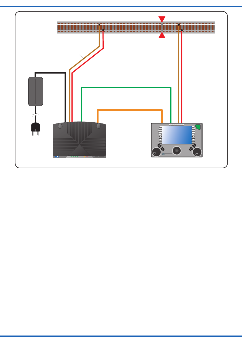
Der Booster 5301 kann von der Digitalzentra-
le über die Schnittstellen „Märklin-Booster“ oder
„CDE“ mit Digitaldaten versorgt werden und ist
geeignet für den Betrieb mit allen handelsüblichen
Digitalzentralen der Formate MM und DCC. Die
Stromversorgung erfolgt über das mitgelieferte
Netzteil. Der optionale Anschluss per LSB (Speed-
Bus) an den Viessmann Commander ermöglicht
die Übertragung von Statusinformationen (z. B.
Belastung, Temperatur) und Kongurationsdaten
zwischen Booster und Commander.
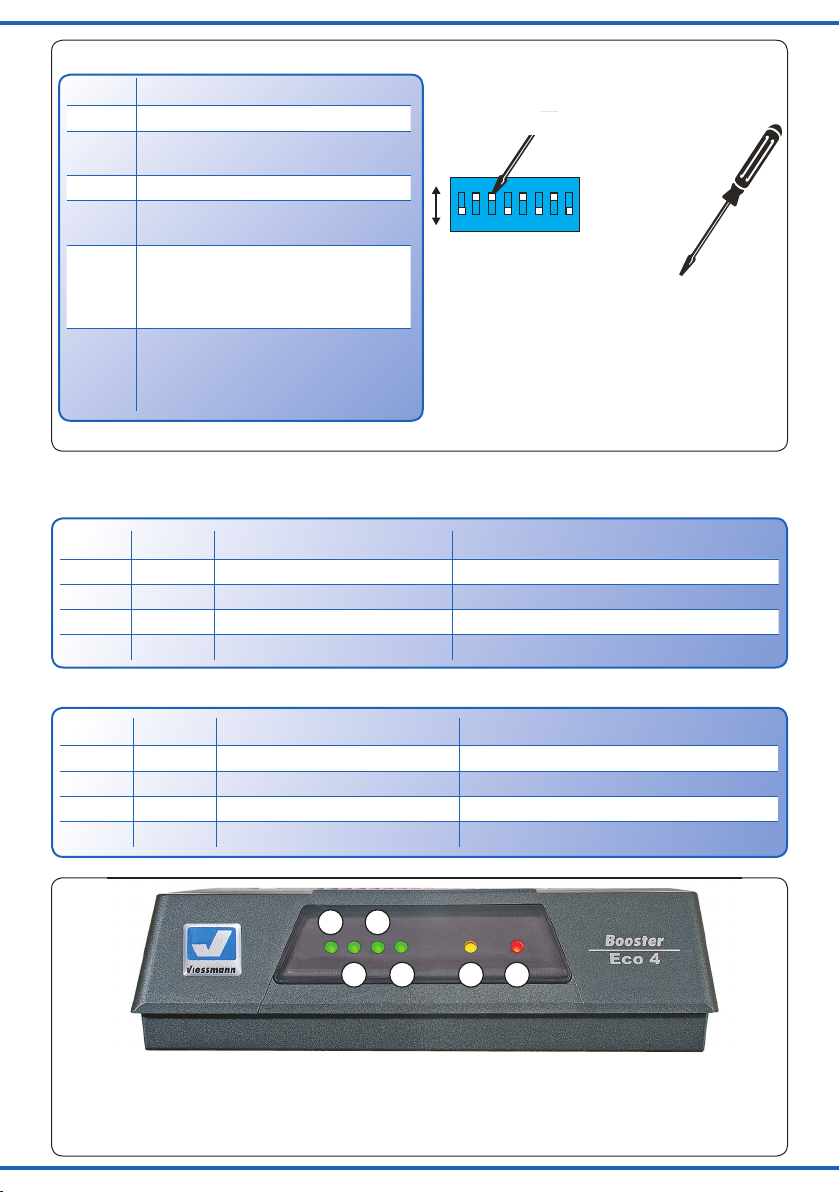
Die Systemeinstellungen des Boosters erfolgen
über den integrierten DIP-Schalter auf der Gehäu-
serückseite oder über das entsprechende Menü
im Commander.
Leistungsanzeigen und Fehlermeldungen lassen
sich über die LEDs an der Gehäusevorderseite
sowie auf dem Commander-Display ablesen.
Eine Besonderheit ist, dass die Kurzschlussmel-
dung an die Zentrale unterdückt werden kann
(DIP-Schalter). Dadurch kann verhindert werden,
dass bei einem Kurzschluss in einem Anlagenab-
schnitt die komplette Anlage abgeschaltet wird.
► Booster 5301,
► Power supply unit with mains cable
► Two green connectors (1x track output and
1x CDE)
► Two additional rubber legs for use when
stacking several housings on each other
► This manual.
2. Introduction / Properties
Boosters supply the required digital current for
digitally controlled layouts. They are needed
whenever the current supplied by the command
station alone is not sufcient to run the trains be-
cause there are too many trains running or other
electric loads operating. As a rule of thumb one
can assume that each command station or boost-
er can run about three to six locomotives simulta-
neously. Additional electric loads such as coach
lighting, sound modules or point motors will re-
duce this number.
Each booster provides energy for its own track
section on the layout with digital current. It re-
ceives the necessary digital signal from the com-
mand station and amplies it before transmitting it
to the track.
It is recommended to separate the circuits for run-
ning trains and switching accessories. In case of
a fault, e.g.: perhaps caused by a short circuit or
overload only part of the layout will be out of op-
eration.
Functions
The booster 5031can be connected to the com-
mand station either with the terminals marked
„Märklin Booster“ or „CDE“ and then receives the
digital signals from the command station. It is suit-
able for operating with all commercially available
command stations supplying the MM or the DCC
data format. The power supply is facilitated with
the supplied mains unit. The optional connection
via the LSB terminals (SpeedBus) to the Viess-
mann Commander allows the transmission of sta-
tus information (e.g.: load, temperature) and con-
guration data between booster and Commander.
The system settings are adjusted by means of the
integral DIP switches at the back of the housing or
via the appropriate menu of the Commander.
Display of power and fault messages can be de-
tected by observing the LEDs at the front of the
housing as well as on the display of the Com-
mander.
The fact that the short circuit feedback to the com-
mand station can be suppressed represents a
special feature of this booster. This feature can be
set with the DIP switch. Thus you can prevent a
shutdown of other parts of the layout in case of a
short circuit.

4
Datenformate DCC / MM
Der Booster 5301 ist multiprotokollfähig und be-
herrscht die Digitalformate DCC und Märklin-Mo-
torola (MM).
Der Booster verstärkt das Gleissignal vollstän-
dig symmetrisch. Das ermöglicht den Einsatz des
ABC-Bremsverfahrens in DCC-Anlagen. Der Boo-
ster ist durch Optokoppler vollständig galvanisch
von der steuernden Zentrale getrennt.
Railcom®
Der Booster 5301 ist Railcom®-fähig und stellt
das sogenannte „Railcom®-Cutout“ im DCC-Si-
gnal zur Verfügung. Dies ermöglicht die Übertra-
gung von Rückmeldeinformationen von den Deco-
dern zur Zentrale in der erzeugten Lücke.
Der Railcom®-Modus des Boosters ist abschalt-
bar, da beim Einsatz mit nicht Railcom®-fähigen
Zentralen Störungen am Gleissignal auftreten
könnten.
Bei reinem Märklin-Motorola-Betrieb sind Stö-
rungen der Datenübertragung durch das
Railcom®-Cutout prinzipiell ausgeschlossen, da
es nicht mehr erzeugt wird.
Update
Der Booster 5301 ist aktualisierbar. Eine neue
Version der Gerätesoftware (Firmware) können
Sie über den LSB mit Hilfe des Commander je-
derzeit selbst auf den Booster aufspielen. Nähere
Informationen nden Sie jeweils in der Anleitung
zum Update.
3. Anschluss
Warnung:
Alle Anschluss- und Montagearbeiten nur
bei abgeschalteter Betriebsspannung
durchführen (Ausnahme: LSB-Anschluss)!
Verwenden Sie zur Versorgung des Boo-
sters das mitgelieferte Netzteil.
Überprüfen Sie Booster und Netzteil regel-
mäßig auf Beschädigungen an den Kabeln
und an den Gehäusen. Offensichtlich be-
schädigte Teile dürfen Sie keinesfalls ver-
wenden. Nehmen Sie keinesfalls Repara-
turversuche selbst vor!
Sorgen Sie für ausreichende Belüftung von
Netzteil und Booster. Der Einbau in ge-
schlossene Fächer, Schubladen etc. kann
zu gefährlichem Wärmestau führen. Über-
hitzung oder Brände können die Folge
sein!
Data formats DCC / MM
The Booster 5301 is multiprotocol capable and
supports the DCC and Märklin Motorola (MM) for-
mats.
The booster ampli es the track signal fully sym-
metrically. This allows the use of the ABC braking
method in DCC layouts. The booster circuits are
completely separated from the command station
by means of an optocoupler.
Railcom®
The Booster 5301 is Railcom® capable and pro-
vides the so called “Railcom®-Cutout” in the DCC
signal. This enables the system to transmit feed-
back information within this gap from the decoders
to the command station.
The Railcom® mode of the booster can be turned
off, because when operating with command sta-
tions that are not Railcom® compatible, a distur-
bance of the track signal may occur.
In pure Märklin Motorola mode the Railcom®-
Cutout will not cause any potential signal distor-
tion since Railcom® is always switched off in Mo-
torola mode.
Update
The booster 5031 is future proof. A new software
version ( rmware) can be loaded onto the boost-
er via the LSB terminals of the Commander at any
time. You will nd more detailed information in the
manual for the update.
3. Wiring
Warning:
Any wiring or installation should only be
done when the booster is disconnected
(exception: LSB connection)!
Always use the supplied power supply unit
for operating the booster.
Regularly check the booster and the mains
unit for damage to the cables or the hous-
ing. Obviously damaged parts may not be
used for service under any circumstances.
Never attempt to repair the unit yourself!
Make sure there is suf cient ventilation for
both the power supply unit and the boost-
er. Installing the devices in enclosures such
as shelves, drawers etc. may lead to a dan-
gerous heat build-up. Overheating or even
re could be the result!

5
Zum Anschluss des Boosters an die Digitalzen-
trale Ihrer Modellbahn sowie die Gleisabschnitte
beachten Sie bitte die unten stehenden Hinweise
und Zeichnungen. Schließen Sie den Booster ge-
mäß der folgenden Abbildungen an.
Always observe the hints and drawings given in
this manual when connecting the booster to the
command station as well as the track sectors of
your model train layout. Wire the booster accord-
ing to the following gures.
Fig. 1
Abb. 1
Übersicht über Geräteanschlüsse Connections overview
2x LSB (geschleift)
(looped) 2x Eingang / input
Märklin Booster
(durchgeschleift / looped)
Eingang CDE (DCC)
input CDE (DCC) Hauptgleisausgang
track output
Netzteil
power supply
2x Eingang /
input
Hauptgleisausgang
Grundlagen Boosteranschluss am Gleis
(Versorgungsabschnitte)
Achtung:
Es ist immer darauf zu achten, dass die
Ausgänge von Zentralen und Boostern
gleichsinnig an den Gleisen angeschlossen
werden. Die Ausgänge „B“ und „0“ müssen
also immer an derselben Gleisseite liegen,
bzw. an Mittelleiter und Schiene.
Stromversorgung / Netzteil
Hinweis:
Das Netzteil des Boosters ist strombegrenzt und
schaltet sich bei Überstrom selbstständig aus und
nach einer gewissen Zeit wieder ein.
Digitalzentrale
Sie können den Booster entweder über die CDE-
Buchse oder die MBooster-Anschlüsse mit dem
Gleissignal versorgen. Wenn beide Signale zur
Verfügung stehen, dann empfehlen wir die Ver-
wendung des CDE-Signals.
DCC: (Abbildung 2 auf Seite 6)
MM: (Abbildung 3 auf Seite 6)
Commander: (Abbildung 4 auf Seite 7)
Hinweis:
Falls Sie eine andere Zentrale als den
Viessmann Commander verwenden, entfällt die
Leitung „LSB“.
Basics: Connecting the booster to the track
(track power sections)
Attention:
Please make sure that the outputs of the
command station and boosters are always
connected to the same side of the tracks.
The outputs “B” and “0” must always be
wired to the same rail (always to the right
rail or always to the left rail) respectively to
the centre contacts and the tracks.
Power supply unit
Note:
The power supply unit of the booster is current
controlled and will automatically switch off in case
of excessive current and back on again after a
certain time.
Digital command station
You can supply the track signal to the booster ei-
ther via the CDE sockets or the MBooster sock-
ets. If both signals are available then we recom-
mend to use the CDE signal.
DCC: (see Figure 2 on page 6)
MM: (see Figure 3 on page 6)
Commander: (see Figure 4 on page 7)
Note:
If you use another command station and not the
Viessmann Commander then the “LSB” cable is
omitted.

6
Fig. 2
Abb. 2
AC
to main track plug
/ Main track
Three-rail-tracks:
red = center rail
red
brown
red
brown
Suitable for all
DCC and MM
digital command
stations!
Anschluss / Connection
zum Hauptgleisanschluss
Hauptgleis
allpolige Trennung empfohlen / complete isolation recommended
230 V ~
Dreileitergleise:
rot = Mittelleiter
5301
Booster
rot
braun
CDE / Märklin-Booster
rot
braun
Für alle DCC- und
MM-Zentralen
geeignet!
CDE
DCC-
Zentrale
DCC-
Zentrale
DCC-
Zentrale
Netzteil
Power supply
AC
to main track plug
/ Main track
Three-rail-tracks:
red = center rail
red
brown
red
brown
Anschluss / Connection
zum Hauptgleisanschluss
Hauptgleis
allpolige Trennung empfohlen / complete isolation recommended
230 V ~
Dreileitergleise:
rot = Mittelleiter
5301
Booster
rot
braun
CDE / Märklin-Booster
rot
braun
MM-Booster
Suitable for all
DCC and MM
digital command
stations!
Für alle DCC- und
MM-Zentralen
geeignet!
DCC-
Zentrale
DCC-
Zentrale
Märklin-
Motorola-
Zentrale
Netzteil
Power supply
Fig. 3
Abb. 3

7
Fig. 4
Abb. 4
Mehrere Booster anschließen
Sie können Ihre Anlage zur Erhöhung der Be-
triebssicherheit in mehrere Versorgungsabschnitte
aufteilen. Jeder Abschnitt wird dabei von einem ei-
genen Booster mit Strom versorgt. Es ist sinnvoll,
die Anlage mit gleichen Boostern zu versorgen.
Teilen Sie Ihre Anlage dazu in einzelne, elektrisch
voneinander getrennte Abschnitte auf, die Sie je-
weils mit einem eigenen Booster versorgen. In je-
dem Versorgungsabschnitt sollten sich durch-
schnittlich max. ca. vier fahrende Züge / Loks be-
nden. Ordnen Sie die Übergänge zwischen den
Versorgungsabschnitten so an, dass diese mög-
lichst selten überfahren werden.
Wir empfehlen, die Übergänge zwischen den Boo-
ster-Abschnitten stets vollständig (Zweileiter: bei-
de Schienen; Dreileiter: stromführende Schienen
und Mittelleiter) zu trennen. Anderenfalls sind Ver-
schlechterungen der Signalqualität möglich.
Dies ist auch möglich, sobald Fahrzeuge die
Trennstelle überbrücken. Daher sollten auch kei-
nesfalls abgestellte Fahrzeuge diese Trennstellen
dauerhaft überbrücken.
Teilen Sie Fahren und Schalten auf. Verwenden
Sie beispielsweise den Gleisausgang Ihrer Zen-
trale zur Versorgung der ortsfesten Schaltgeräte
(Decoder) auf der Anlage. Zur Versorgung der
Connecting several boosters
For increased reliability you can subdivide your
layout into several supply sectors. Each sector is
then supplied with power from its own booster. It
is recommended to use the same type of booster
for the entire layout.
Subdivide your layout into individual, electrically
isolated sectors to be wired to one booster each.
On average there should be no more than about
four trains or locomotives running in each sector.
Locate the insulation gaps between the sectors in
such a ways that they are not crossed very often.
We recommend insulating both conductors be-
tween the booster sectors (standard DC resp.
DCC arrangement: insulate both rails; three-rail
system: insulate the centre conductor and the
rails). Insulating only one side may lead to a re-
duced signal quality.
Lower signal quality may also be present when-
ever a vehicle crosses the insulating gaps. There-
fore no vehicle should be “parked” for longer peri-
ods while standing across the gaps.
Subdivide the circuits for running trains and
switching accessories. For instance, use the track
output of your command station for controlling sta-
tionary decoders for accessories and use sepa-
rate boosters for your track sectors.
Connecting several boosters:
CDE: Wire the conductors of the sockets parallel
and also connect them to the next booster.
Märklin: Both sockets of the booster are through
AC
to main track plug
/ Main track
Three-rail-tracks:
red = center rail
e. g. Commander
red
brown
red
brown
Anschluss / Connection
zum Hauptgleisanschluss
Hauptgleis
allpolige Trennung empfohlen / complete isolation recommended
230 V ~
Dreileitergleise:
rot = Mittelleiter
z. B. Commander
5301
Booster
rot
braun
CDE / Märklin-Booster
rot
braun
LSB optional
CDE
Commander
Netzteil
Power supply

8
Fig. 6
Abb. 6
LED:
1 - 4: grün / green
5: gelb / yellow
6: rot / red
1
2
3
4 5 6
ON
12345678
WnP
DIP-Schalter
Ein
Aus
DIP-Switch
/ On
/ Off
Fig. 5
Abb. 5
DIP-Nr. Funktion / function
1 Reset / Reset
2 Railcom® / RailCom Cut-out is
switched on/off
3 Nicht benutzt / not in use
4+5 Einstellung der Ausgangsspannung /
Adjusting the output voltage
6+7
Einstellung der Ausgangsstroms u.
d. Reaktion auf Überlast /
Adjusting the output current and the
response to overload
8
Kurzschlussmeldung an Zentrale
report short circuit /
Transmit short circuit indication to
the command station
S6 S7 Wert / Reaktion Value / Response
on on voller Strom (3,5 A), schnell full current (ca. 3.5 A), fast response
on off mittlerer Strom (2,7 A), schnell medium current (ca. 2.7 A), fast response
off on kleiner Strom (2 A), schnell low current (ca. 2 A), fast response
off off voller Strom (3,7 A), langsam full current (ca. 3.7 A), slow response
Einstellung des Ausgangsstroms und der
Reaktion auf Überlast:
Adjusting the output current and the response
to overload:
S4 S5 Wert / Reaktion Value / Response
on on ca. 18,5 V Approx. 18.5 V
on off ca. 17 V Approx. 17 V
off on ca. 15 V Approx. 15 V
off off ca. 13 V Approx. 13 V
Einstellung der Ausgangsspannung: Adjusting the output voltage:

9
Anzeige der Betriebsbereitschaft / Kurzschluss / Fehlerzusände mit LEDs
Linke grüne LED
blinkt langsam
Gleisspannung eingeschaltet und keine nennenswerte
Stromabgabe, d. h. kleiner als 300 mA (= Bereitschaftsanzeige)
Leuchten mehrerer grüner
LEDs in einer Reihe Maß für die aktuelle Leistungsabgabe (v.l.n.r.)
Leuchten nur
der roten LED Kurzschluss an diesem Boosterausgang; Booster abgeschaltet
Leuchten der linken
grünen LED und
der roten LED
Kein Signal von der Zentrale vorhanden; Zentrale nicht
eingeschaltet oder wegen Kurzschluss ausgeschaltet
Leuchten der roten
und gelben LED Temperatur zu hoch; Booster überhitzt und abgeschaltet
Leuchten der linken
grünen LED und der
gelben und roten LED
Spannung zu hoch; entweder ist die Versorgungspannung zu
hoch oder es liegt eine hohe Fremdspannung am Gleis
Blinken der dritten grünen
LED (v.l.n.r.)
Booster bendet sich
im Update-Modus
Abb. 7
Indicating readiness for service / short circuit / faults with LEDs
The left green LED blinks
slowly
Track voltage is turned on and there is (virtually) no current
owing, that is, the current is less than 300 mA (= indication
of readiness for service)
If several LEDs light up
in a row, for instance
form left to right
this is a measure for the current power consumed
Only the red LED lights
up short circuit on this booster output; Booster is switched off
The green and the red
LED light up
there is no signal from the command station; the command
station is not switched on or has shutdown due to short circuit
The red and the yellow
LED light up
the temperature is too high; Booster is overheating and has
switched off
The left green LED and
the yellow and red LED
are light up
the voltage is too high; either due to the fact the supply
voltage is too high or there is a high voltage from another
source applied to the tracks
The third green LED
(from left to right) is
blinking
this indicates that the booster is in the update mode
Fig. 7

10
verschiedenen Fahrstrombereiche
können Sie dann einen oder mehrere
Booster nutzen.
CDE: Die Leitungen an den Buch-
sen parallel schalten und jeweils zum
nächsten Booster weiterleiten.
Märklin: Die beiden Buchsen am
Booster sind durchgeschleift. Es spielt
also keine Rolle, welches Kabel zur Zentrale führt
und welches zum jeweils nächsten Booster.
Tipp:
Wenn Sie mehrere Booster übereinander stellen
wollen, so können Sie die hinteren Gehäusefüße
gegen die höheren austauschen. So stehen die
Geräte im erforderlichen Abstand und parallel zu-
einander. Beachten Sie, dass diese Aufstellweise
die Kühlung geringfügig beeinträchtigen kann.
4. Konguration / Einstellungen
Die Einstellung des Boosters erfolgt entweder
über den DIP-Schalter auf der Gehäuserücksei-
te oder über das entsprechende Menü des Com-
manders. Kongurationsbefehle des Comman-
ders haben gegenüber dem DIP-Schalter immer
Vorrang.
Wenn der LSB-Anschluss zu einem Commander
hergestellt wurde, so sendet der Commander bei
entsprechender Software-Version die Information
zur Einstellung des Boosters – die Schalterstel-
lungen werden nicht mehr beachtet!
Wenn kein LSB-Anschluss verwendet wird, z.B.
bei Verwendung einer anderen Digitalzentrale, so
werden automatisch die Schalterstellungen zur
Konguration verwendet.
Dies gilt auch, wenn Sie den Booster vom LSB
getrennt haben und danach die Stellung des
Schalters verändern: Ab sofort werden die neuen
Stellungen wirksam.
Vor Inbetriebnahme des Boosters am Gleis sollten
Sie die Ausgangsspannung auf den für Ihre
Baugröße passenden Wert einstellen. Idealerwei-
se stellen Sie die Digitalzentrale und weitere Boo-
ster auf denselben Wert ein.
Einstellungen über Commander
Die folgenden Parameter lassen sich über den
Commander einstellen:
• Ausgangsstrom: gestuft bis 3,5 A
• Ausgangsspannung: gestuft von 13 bis 18,5 V
• Weitere Betriebseigenschaften
Hinweise zur Bedienung der Commander-Menüs
erhalten Sie im Referenzhandbuch des Comman-
ders.
wired. Therefore it does not matter which cable
leads to the central unit and which goes to the
next booster.
Hint:
If you want to place several boosters on top of
each other then you may exchange the back legs
against higher ones, which are supplied with the
device. Thus the devices will have the right spac-
ing between them and are parallel to each other.
Please bear in mind, that this type of arrangement
may reduce the cooling to a certain degree.
4. Conguration / Setting
parameters
The setting of the booster can either be done
with the aid of the DIP switches at the back of the
housing or via the appropriate menu of the Com-
mander. Conguration commands issued by the
Commander will always get preference over the
setting of the DIP switches.
Once the connection to the LSB sockets of the
Commander have been made, the Commander
will transmit the signals for setting the booster and
the position of the DIP switches will be ignored!
This process only works provided the appropriate
software (rmware) version is available.
If the LSB connection is not used when you for in-
stance connect to another type of command sta-
tion then the DIP switches will automatically have
priority for conguring the booster.
This is also true in case you have disconnected
the booster form the LSAB sockets and subse-
quently have changed the setting of a switch: the
new settings will be effective immediately.
Prior to connecting the booster to the tracks you
should set the track voltage to the appropriate val-
ue suitable for your type of trains (scale). Ideally
you will set the command station and all boosters
to the same output value.
Setting with the Commander
You can adjust the following parameters with the
Commander:
• Output current: in steps up to 3.5 A
• Output voltage: in steps from 13 to 18.5 V
• Other operating characteristics
You will nd hints regarding working with the men-
us of the Commander in the reference handbook
for the Commander.
Nenngröße
Scale
empfohlene Gleisspannung
recommended track voltage
Z 12 V
N / TT 14 V
H0 16 - 18 V

11
Einstellungen über DIP-Schalter (siehe Abb. 5)
Die folgenden Parameter lassen sich über den
DIP-Schalter einstellen:
S8 on: Kurzschlussmeldung an Zentrale senden
S3: nicht benutzt
S2 on: Railcom®-Cutout eingeschaltet
S1 on/off: Programmierschalter: Löschen der
LSB-Adrdesse. Zum Löschen der LSB-Adres-
se betätigen Sie bitte den Reset-Schalter inner-
halb von 2 Sekunden von der Stellung „on“ auf
„off“ und wieder zurück. Die LSB-Busadresse wird
dann gelöscht und das Gerät meldet sich neu am
Commander an.
Bitte beachten Sie, dass die Schalterstellungen
auch während des Betriebs des Boosters eingele-
sen werden. Änderungen werden also sofort gül-
tig.
Werkeinstellungen
Ohne LSB (SpeedBus) gelten die Einstellungen
am DIP-Schalter. Ab Werk : Alle Schalter oben.
Wenn per LSB ein Commander angeschlossen
ist, haben dessen Kongurationsbefehle Vorrang
vor dem DIP-Schalter.
Elektrische Ausgangswerte ab Werk: 18,5 V;
3,5 A;
Sonstige Parameter: Railcom®-Cutout einge-
schaltet; Kurzschlussmeldung an Zentrale einge-
schaltet.
5. Betrieb
Displayanzeigen
Die LEDs an der Vorderseite des Boosters zeigen
den aktuellen Betriebszustand an.
Beim Start des Boosters (Energieversorgung her-
stellen) leuchten nacheinander als Leuchtentest
alle LEDs auf, bis alle an sind. Danach zeigen die
LEDs den aktuellen Betriebszustand.
Anzeige der Betriebsbereitschaft / Kurz-
schluss / Fehlerzustände mit LEDs
(siehe Abb. 6 + 7):
Anzeige der Belastung
Es gelten in etwa die folgenden Zusammenhänge:
• linke grüne LED leuchtet: Strom > ca. 300mA
(ca. 320 / 170 mA)
• zwei grüne LEDs leuchten: Strom > ca. 700
mA (ca. 540 / 400 mA)
• drei grüne LEDs leuchten: Strom > ca. 1200
mA (ca. 930 / 700 mA)
• vier grüne LEDs leuchten: Strom > ca. 1900
mA (ca. 1500 / 1100 mA)
Setting parameters with DIP switches
(see Fig 5.)
The following parameters can be adjusted with the
DIP switches:
S8 on: Transmit short circuit indication to the com-
mand station
S3: not in use
S2 on: Railcom® Cut-out is switched on
S1 on/off: Programming switch: Deleting the LSB
address
If you wish to delete the LSB address simply tog-
gle the reset button between “On” and “Off” with-
in two seconds. Then the LSB bus address will be
deleted and the device will register once again at
the Commander.
Please note that the switch positions can be read
out even during operation of the booster. Any
changes will be effective immediately.
Factory default settings
Without the LSB (SpeedBus) the booster is cong-
ured according to the positions of the DIP switch-
es. Ex works all switches are in the “Up” position.
If the LSB is connected to the Commander, then
the conguration commands issued by the Com-
mander have priority over those from the DIP
switches.
Electrical outputs values ex works: 18.5 V; 3.5 A;
Other parameters: Railcom® Cut-out is switched
on; short circuit report to command station is ac-
tive.
5. Operation
Status displays
The LEDs at the front of the booster show the cur-
rent operational status.
When starting the booster (power on) all LEDs
light up in sequence for testing until they are all lit.
After that the LEDs show the current status.
Indicating readiness for service / short circuit /
faults with LEDs (see Fig. 6 + 7):
Indicating the load
Below we list the indications regarding the current:
• Left green LED lights up: current > ca.
300mA (ca. 320 / 170 mA)
• Two green LEDs light up: current > ca. 700
mA (ca. 540 / 400 mA)
• Three green LEDs light up: current > ca.
1200 mA (ca. 930 / 700 mA)
• Four green LEDs light up: current > ca. 1900
mA (ca. 1500 / 1100 mA)

12
• grüne LEDs und gelbe LED leuchten: Strom
> ca. 2700 mA (ca. 2100 / 1500 mA)
• grüne und gelbe LEDs leuchten, rote LED
blitzt länger auf : Strom > ca. 3200 mA (ca.
2500 / 1800 mA)
• grüne, gelbe und rote LEDs leuchten : Strom
> ca. 3400 mA, nahezu Überlast erreicht (ca.
2600 / 1950 mA)
(Werte in Klammern geben die Ströme an, die in
etwa bei reduzierter Stromabgabe gelten.)
Die Anzeige der Ströme auf dem Commander er-
folgt analog zu dieser Tabelle.
Außerdem gibt die Commanderanzeige eine Infor-
mation über die Betriebstemperatur des Boosters.
Das Feld neben der Belastungsskala zeigt die
Nummer des Boosters und die Temperaturstufen
50, 70 und 80 Grad C an.
Bei mehr als 85 Grad C schaltet der Booster ab.
Nach Abkühlung unter diesen Wert schaltet er
wieder ein.
Einschalten / Ausschalten
Der Booster schaltet sich selbst ein, sobald von
der angeschlossenen Zentrale über CDE oder
Märklin-Booster ein Steuersignal anliegt.
Wenn kein Steuersignal seitens der Zentrale an-
liegt oder im Fehlerfall ist die Endstufe des Boo-
sters ausgeschaltet.
Kurzschluss
Der Booster schaltet sich bei Kurzschluss nach
ca 0,5 bis 1,5 Sekunden (abhängig von der Art
der Überlastung und der Temperatur) selbststän-
dig ab. Gleichzeitig sendet der Booster eine Kurz-
schlussmeldung an die steuernde Zentrale und
löst dort den Stop der Anlage aus.
Es ist jedoch nicht immer erwünscht, dass wegen
eines einzelnen überlasteten Stromkreises die
ganze Anlage abgestellt wird. Falls Sie dies nicht
wünschen, können Sie per DIP-Schalter auswäh-
len, dass der Booster die Meldung nicht über die
Hardware-Schnittstelle CDE (Leitung E) bzw. Mär-
klin-Booster meldet. Er versucht dann nach ca. 3
bis 5 Sekunden (abhängig von der Temperatur)
den Neustart.
Leistung / Auslastung
Der Booster liefert eine Dauerausgangsleistung
von bis zu 65 VA (3,5 A bei 18,5 V). Kurzzeitig
kann der Booster einen Spitzenstrom von 4 A lie-
fern.
Die aktuelle Belastung zeigt der Booster auf dem
LED-Display (siehe Abb 7) sowie auf dem Com-
mander-Bildschirm an.
• All green LEDs and the yellow LED light up:
current > ca. 2700 mA (ca. 2100 / 1500 mA)
• Green and yellow LEDs light up, and the red
LED ashes for a bit : current > ca. 3200 mA
(ca. 2500 / 1800 mA)
• Green, yellow and red LEDs light up : current
> ca. 3400 mA, almost overload (ca. 2600 /
1950 mA)
(The values in brackets show the approximate
currents that are supplied when the current is re-
duced.)
The display of currents on the Commander follows
the principle of this table.
The Commander also provides information re-
garding the operating temperature of the booster.
The eld next the load scale shows the number of
the booster and the temperature steps 50, 70 and
80 degrees C.
If the temperature reaches 85 degrees C, the
booster will switch itself of.
Once the booster has cooled off it will automati-
cally switch on again.
Switching on / off
The booster switches itself on as soon as a signal
from the command station is available (either via
CDE or the Märklin booster).
If there is no signal from the command station or
in case of an fault the output stage of the booster
is switched off.
Short circuit
In case of a short circuit the booster automatical-
ly switches off after about 0.5 to 1.5 seconds (sub-
ject to the type of overload and the temperature).
At the same time the booster transmits a signal
reporting the short circuit to the command station
and triggers the STOP function of the command
station.
However, it is not always desirable to turn off the
entire layout due to one single overloaded cir-
cuit. If you do not want the booster to send this
short circuit report to the command station via the
CDE cable (conductor E) respectively the Märk-
lin booster, you can set this by means of the DIP
switches. In this case the booster will attempt to
start again after about 3 to 5 seconds (subject to
the temperature).
Power / workload
The booster provides a continuous power of up to
65 VA (3.5 A at 18.5 V). the maximum short term
current is 4 A.
The booster indicates the current load on the LED
display (also refer to the table describing the dis-
play indications) as well as on the monitor of the
Commander.

13
Beachten Sie, dass ein Herabsetzen der Aus-
gangsspannung zu vermehrter Hitzeentwicklung
im Gehäuse führt. Dies kann zu temperaturbe-
dingtem Abschalten führen.
6. Fehlersuche und Abhilfe
Jedes Viessmann-Produkt wird unter hohen Qua-
litätsstandards gefertigt und vor seiner Ausliefe-
rung geprüft. Sollte es dennoch zu einer Störung
kommen, prüfen Sie bitte als erstes die Stromzu-
fuhr und die Verkabelung.
Wenn Sie die Fehlerursache nicht nden können,
geben Sie den Booster in der zugehörigen Ver-
packung inkl. Netzteil zu Ihrem Fachhändler oder
senden Sie ihn zur Reparatur bitte direkt an den
Viessmann-Service (Adresse siehe unten).
1) Der Booster wird ungewöhlich heiß ohne Feh-
lermeldung.
Trennen Sie sofort die Verbindung zur Versor-
gungsspannung!
Mögliche Ursache: Zu wenig Kühlung oder Defekt
am Booster.
2) Die LEDs am Booster leuchten nicht und die
Loks lassen sich nicht ansteuern.
Mögliche Ursache: Die Spannungsversorgung ist
unterbrochen.
Überprüfen Sie die Anschlüsse an die Span-
nungsversorgung (Netzteil, Netzsteckdose).
3) Die rote LED sowie oder mehrere weitere LEDs
leuchten und die Loks lassen sich nicht ansteu-
ern.
Ursache: Der Booster hat einen Fehlerzustand er-
kannt. Prüfen Sie die Art des Fehlers anhand des
Absatzes „Displayanzeigen“.
Beispiel: Der Booster schaltet ab. Die rote sowie
die gelbe LED leuchten.
Mögliche Ursache: Der Booster wird nicht ausrei-
chend belüftet und hat sich überhitzt.
Sorgen Sie dafür, dass über die Lüftungsschlitze
auf der Ober- und der Rückseite des Boosters ein
ungehinderter Luftaustausch möglich ist.
Mögliche Ursache dafür: Die eingestellte Gleis-
spannung ist auf einen sehr niedrigen Wert ein-
gestellt. Die Leistung, die aus der Differenz zwi-
schen der tatsächlichen Netzteilspannung und der
gewünschten Gleisspannung und dem entnom-
menen Strom entsteht, muss vom Booster als
Wärme abgeführt werden. Ist diese Leistung zu
hoch, überhitzt der Booster und schaltet infolge
Übertemperatur ab.
Please note that reducing the output voltage may
lead to increased heat load inside the housing.
This may lead to automatic shutdown due to high
temperature.
6. Troubleshooting
Each Viessmann product is manufacture accord-
ing to stringent quality standards and is tested pri-
or to delivery. Should a fault occur despite these
measures rst check the power supply and the
wiring.
Should you not be able to nd the cause of the
fault put the booster in its original packaging in-
cluding the power supply unit and return it to your
dealer or hobby shop or send it directly to the
Viessmann service department (see below for the
address).
1) The booster gets unusually hot without an er-
ror message
Disconnect the power supply immediately!
Potential cause: insufcient cooling or defect
booster.
2) The LEDs on the booster do not light up and
the locos cannot be controlled anymore.
Potential cause: The power supply is interrupted.
Check the connections to the power supply unit
(on the device and also the mains plug and wall
outlet).
3) The red LED as well as several other LEDs
light up and the locos cannot be controlled any-
more.
Cause: The booster has detected a fault. Check
which type of fault it is as described in the chapter
„Indicating faults“.
Example: The booster switches off. The red as
well as the yellow LED light up
Potential cause: The booster is not sufciently
ventilated and is overheated.
Make sure that the ventilation slots at the top and
the back of the booster facilitate an unimpaired
air ow.
Potential cause for this: the set track voltage is
adjusted to a very low value.
The power corresponding to the difference be-
tween the actual voltage supplied by the power
supply unit and the desired track voltage has to be
converted into heat by the booster. If this power is
too much, then the booster overheats and auto-
matically is turned off due to high temperature.

14
7. Gewährleistung
Jedes Produkt wird vor seiner Auslieferung auf
vollständige Funktion überprüft. Der Gewährlei-
stungszeitraum beträgt 2 Jahre ab Kaufdatum.
Tritt in dieser Zeit ein Fehler auf, setzen Sie sich
bitte direkt mit der Firma Viessmann Modellspiel-
waren in Verbindung. Wird nach Überprüfung des
Modells ein Herstell- oder Materialfehler festge-
stellt, wird das Produkt kostenlos instandgesetzt.
Von der Gewährleistung ausgeschlossen sind Be-
schädigungen des Modells, die durch unsach-
gemäße Behandlung, Nichtbeachten der Bedie-
nungsanleitung, nicht bestimmungsgemäßen Ge-
brauch, Überlastung, unzulässig hoher Umschal-
timpuls von analogen Wechselstromanlagen, feh-
lerhafte Verdrahtung der Modellbahnanlage, ei-
genmächtigen Eingriff, bauliche Veränderungen,
Gewalteinwirkung, Überhitzung u. ä. verursacht
werden.
Jede Haftung für Schäden und Folgeschäden
durch nicht bestimmungsgemäßen Gebrauch,
Nichtbeachtung der Bedienungsanleitung, eigen-
mächtigen Eingriff, bauliche Veränderungen, Ge-
walteinwirkung, Überhitzung, Überlastung, Feuch-
tigkeitseinwirkung u. ä. ist ausgeschlossen.
Wenn Sie die Fehlerursache nicht nden können,
senden Sie das Modell zur Reparatur bitte direkt
an den Viessmann-Service (Adresse siehe unten).
7. Warranty
Each product undergoes a full function test prior
to delivery. The warranty period is two years from
date of purchase. Should there be a fault during
this period, please contact Viessmann Modell-
spielwaren directly. If we nd a manufacturing or
material fault after checking the product, then we
will repair the product free of charge.
From the warranty excluded are damaged prod-
ucts due to inappropriate handling or use, ignor-
ing the user manual, overload, not permitted high
switching pulses in analogue AC layouts, faulty
wiring of the model train layout, unauthorised
changes to the product, effects caused by undue
force, overheating and similar causes.
If you cannot establish the cause of the fault, send
this model for repair directly to the Viessmann
Service (address see below).

15
Notes
Notizen

Modellbauartikel, kein Spielzeug! Nicht geeignet für Kinder unter
14 Jahren! Die Anschlussdrähte niemals in eine Steckdose einführen!
Anleitung aufbewahren!
Model building item, not a toy! Not suitable for children under 14
years! Never put the connecting wires into a power socket! Keep
these instructions!
Ceci n’est pas un jouet. Ne convient pas aux enfants de moins de
14 ans ! Ne jamais introduire les ls d’alimentation dans une prise!
Conservez ce mode d’emploi !
Modelbouwartikel, geen speelgoed! Niet geschikt voor kinderen
onder 14 jaar! De aansluitdraden nooit in een wandcontactdoos steken!
Gebruiksaanwijzing bewaren!
Articolo di modellismo, non è un giocattolo! Non adatto a bambini
al di sotto dei 14 anni! Non inserire mai i fili di collegamento in una
presa! Conservare instruzioni per l’uso!
Artículo para modelismo ¡No es un juguete! No recomendado para
menores de 14 años! ¡No introducir nunca los hilos de conexiones en
un enchufe de la red eléctrica! Conserva las instrucciones de servicio!
Modellspielwaren GmbH
RailCom®ist ein eingetragenes Warenzeichen der / is a registered trademark of Lenz-Elektronik GmbH, Gießen.
Märklin ist ein eingetragenes Warenzeichen der / is a registered trademark of Gebr. Märklin & Cie GmbH, Göppingen.
Motorola ist ein eingetragenes Warenzeichen der / is a registered trademark of Motorola Inc., Tempe-Phoenix / Arizona (USA).
Weitere Produkt- oder Firmennamen können Marken oder Handelsnamen ihrer jeweiligen Inhaber sein.
9. Technische Daten
Maße: 150 x 108 x 45 mm
Gewicht: 225 g
Anschlüsse:
• 1 Power 2,5 mm Hohlstecker-Buchse für 18
V DC (Commander-Netzteil)
• 1 Gleisausgang
• 1 CDE für DCC-Booster (isoliert)
• 2 Märklin Booster (durchgeschleift, isoliert)
• 2 LSB für Commander (durchgeschleift, isoliert)
Betriebsspannung: 19 V
Betriebsstrom: max.: 4,5 A
Digitalsysteme: DCC / MM
Schutzklasse / Isolation: IP 30
Railcom®-Cutout: ja, einstellbar
Temperatur / rel. Feuchtigkeit (Betrieb):
+8 - +40 °C / max. 85 % nicht betauend.
Temperatur / rel. Feuchtigkeit (Lagerung):
0 – 60 °C / max. 85 % nicht betauend.
Der Booster wurde gemäß den Anforderungen
der EG-Richtlinie 2004/108/EG über die elek-
tromagnetische Verträglichkeit entwickelt und
trägt die entsprechende CE-Kennzeichnung.
9. Technical Data
Dimensions: 150 x 108 x 45 mm
Weight: 225 g
Connections:
• 1 Power 2.5 mm hollow plug-socket for 18 V
DC (Commander power supply unit)
• 1 Track output
• 1 CDE for DCC booster (isolated)
• 2 Märklin booster (through wired, isolated)
• 2 LSB for Commander (through wired, isolated)
Operating voltage: 19 V
Operating current: max. 4.5 A
Digital systems: DCC / MM
Protection class / degree of protection: IP 30
Railcom® Cut-out: yes, adjustable
Temperature / rel. humidity (during operation):
+8 - +40 °C / max. 85 % not bedewed.
Temperature / rel. humidity (storage): 0 – 60 °C
/ max. 85 % not bedewed.
The booster was developed in accordance with
the EG directive 2004/108/EG regarding elec-
tromagnetic compatibility and bears the appro-
priate CE mark.
8. Umweltschutzhinweis
Dieses Produkt darf am Ende seiner Lebensdauer
nicht über den normalen Hausmüll entsorgt wer-
den. Es muss an einem Sammelpunkt für das Re-
cycling von elektrischen und elektronischen Ge-
räten abgegeben werden. Das Mülleimer-Symbol
auf dem Produkt, der Bedienungsanleitung oder
der Verpackung weist darauf hin. Die Werkstoffe
sind gemäß ihrer Kennzeichnung wiederverwert-
bar.
8. Environmental Note
This product may not be disposed of in normal
household garbage at the end of its life. It must
be dropped off at a collection station for recycling
of electrical and electronic devices. The symbol
showing the trash can on the product, the user
manual and the packing point this out. The materi-
als can be reused according to their identication.
92343
Stand 01
11/2012
TB
Table of contents