VigilLink VLEX-HT2150U-TR User manual

VLEX-HT2150U-TR
18Gbps HDBaseT Extender with USB 2.0 150m
VER 1.0

Thank you for purchasing this product
Please read these instructions carefully for optimum performance and safety
before connecting, operating, or adjusting this product. Please keep this manual
for future reference.
A surge protection device is recommended.
This product contains sensitive electrical components that electrical spikes
may damage, surges, electric shocks, lightning strikes, etc. The use of surge
protection systems is highly recommended to protect and extend thelife of
your equipment.
Table of Contents
1. Introduction. ........................................................................................
1
2. Features. ..............................................................................................
1
3. Package Contents. .............................................................................
2
4. Specifications. .....................................................................................
2
5. Operation Controls and Functions. ....................................................
4
5.1 Transmitter Panel. ..........................................................................
4
5.2 Receiver Panel. .............................................................................
5
5.3 IR Pin Definition ..............................................................................
6
6. Application Example. .........................................................................
7

1 / 7
1. Introduction
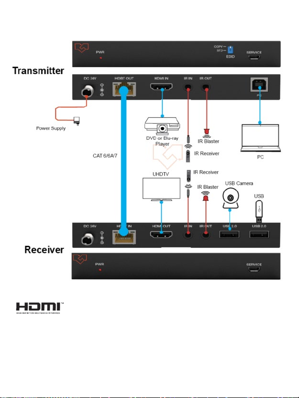
This 18Gbps HDBaseT Extender can extend the HDMI signal, bi-directional
IR control signal, and USB KVM signal to a distance up to 150m via a single
CAT6 cable. This product converts HDMI signal to standard HDBaseT signal
and transmits it through a LAN cable. It can easily control the signal source
deviceor display device from the remote end through a bi-directional IR
signal pass-through function. Video resolution up to 4K2K@60Hz YUV 4:4:4.
It also supports USB 2.0 transmission and POC function.
The extender can be widely used in other fields such as video conference
systems, multimedia signal broadcasting, HDMI signal extension, etc.
2. Features
☆HDMI 2.0b and HDCP 2.2 compliant
☆Support 18Gbps video bandwidth
☆Support video resolution up to 4K2K@60Hz YUV 4:4:4
☆The transmission distance can be extended up to 492ft / 150m at the
resolution of 1080P@60Hz, or 394ft / 120m at 4K2K@60Hz 4:4:4 via a
single CAT6 cable
☆Support bi-directional IR signal and USB KVM signal pass-through
☆Support bi-directional POC (Power over Cable) function
☆Support USB 2.0 transmission
☆EDID management
☆Compact design for easy and flexible installation

2 / 7
3. Package Contents
①1 x 18Gbps HDBaseT Extender (Transmitter)
②1 x 18Gbps HDBaseT Extender (Receiver)
③1 x IR Blaster cable (1.5 meters)
④1 x IR Wideband Receiver cable (1.5 meters)
⑤4 x Mounting Ears
⑥ 8 x Machine Screws (KM3*4)
⑦1 x 24V/1A Locking Power Supply
⑧1x User Manual
4. Specifications
Technical
HDMI Compliance
HDMI 2.0b
HDCP Compliance HDCP 2.2
Video Bandwidth
18Gbps
Video Resolution
Up to 4K2K@60Hz YUV 4:4:4
USB Compliance USB 2.0
IR Level
5Vp-p
IR Frequency
Wideband 20K-60KHz
Transmission
Distance
1080P@60--150m, 4K60 --120m
Color Space RGB 4:4:4, YCbCr 4:4:4, YCbCr 4:2:2, YCbCr 4:2:0
Color Depth
8-bit, 10-bit, 12-bit (1080P)
8-bit (4K60)
8-bit, 10-bit, 12-bit (4K24/30)
HDR HDR, HDR10, HDR10+, Dolby Vision, HLG
Audio Format LPCM 7.1CH, Dolby True HD, and DTS-HD Master
ESD Protection
Human body model — ±8kV (Air-gap discharge) &
±4kV (Contact discharge)

3 / 7
Connection
Transmitter
Input: 1×HDMI IN [Type A, 19-pin
female]1×IR IN [3.5mm Stereo
Mini-jack] 1×SERVICE [Micro-
USB jack] 1×USB [USB-B, 4-pin
female]
Output: 1×HDBT OUT [RJ45]
1×IR OUT [3.5mm Stereo Mini jack]
Receiver
Input: 1×HDBT IN [RJ45 with light]
1×IR IN [3.5mm Stereo Mini jack]
1×SERVICE [Micro-USB jack]
Output: 1×HDMI OUT [Type A, 19-pin
female]1×IR OUT [3.5mm Stereo
Mini-jack] 2×USB 2.0 [USB-A, 4-pin
female]
Mechanical
Housing Metal Enclosure
Color
Black
Dimensions
Transmitter / Receiver:140mm (W)×65mm (D)×18mm (H)
Weight
Transmitter: 245g, Receiver: 249g
Power Supply
DC 24V/1A;
Support
bi-directional
POC function
Power Consumption 13.2W (Max.)
Operating Temperature
0°C ~ 40°C / 32°F ~ 104°F
Storage Temperature
-20°C ~ 60°C / -4°F ~ 140°F
Relative Humidity
20~90% RH (non-condensing)

4 / 7
5. Operation Controls and Functions
5.1 Transmitter Panel
No.
Name
Function Description
1PWR LED The red LED is on when the Transmitter is powered on.
2EDID DIP
switch
Used for audio EDID setting (dial to COPY by default).
COPY: Copy the EDID of the HDMI OUT port of the
Receiver.STD: Default 1080P 2CH
3SERVICE Firmware update port.
4
DC 24V
DC 24V/1A power input port.
Note that the extender supports the POC function, which means that
either Transmitter or Receiver is connected to a 24V/1A power supply;
the otherdoesn’t need a power supply.
5HDBT OUT
HDBT output port, connecting to the HDBT IN port of the
Receiver with CAT6 cable.
6
Link Signal
Indicator
(Green)
▪
Illuminating: Transmitter and Receiver are in good connection
status.
▪
Flashing: Transmitter and Receiver are in poor connection
status.
▪
Dark: The transmitter and Receiver are not connected.
7
Data Signal
Indicator
(Yellow)
▪
Illuminating: HDMI signal with HDCP.
▪
Flashing: HDMI signal without HDCP.
▪
Dark: No HDMI signal.
8HDMI IN
HDMI signal input port, connecting to HDMI source device
such as DVD play or Set Top Box.

5 / 7
No.
Name
Function Description
9IR IN Connecting to the IR receiver cable, the IR receive signal
will emitto the IR OUT port of the Receiver.
10 IR OUT Connect to IR blaster cable; the IR emit signal is from the IR
IN port of the Receiver.
11 PC USB-B port, connecting to PC.
5.2 Receiver Panel
No.
Name
Function Description
1Power LED The power LED is on when the Receiver is powered on.
2SERVICE Firmware update port.
3
DC 24V
DC 24V/1A power input port.
Note that the extender supports the POC function, which means that
either Transmitter or Receiver is connected to a 24V/1A power supply;
the otherdoesn’t need a power supply.
4HDBT IN
HDBT input port, connecting to the HDBT OUT port of the
Transmitter with CAT6 cable.
5
Link Signal
Indicator
(Green)
▪
Illuminating: Transmitter and Receiver are in good connection
status.
▪
Flashing: Transmitter and Receiver are in poor connection
status.
▪
Dark: The transmitter and Receiver are not connected.

6 / 7
No.
Name
Function Description
6
Data Signal
Indicator
(Yellow)
▪
Illuminate HDMI signal with HDCP.
▪
Flash: HDMI signal without HDCP.
▪
Dark: No HDMI signal.
7HDMI OUT
HDMI signal output port, connecting to HDMI display
devicessuch as TV or monitor.
8IR IN
Connect to the IR receiver cable. The IR signal will send
to the IR OUT port of the Transmitter.
9IR OUT
Connect to the IR blaster cable; the IR signal is from IR
IN port of the Transmitter.
10 USB 2.0
ports
Two USB-A ports connect to USB 2.0 devices. (The
maximum output current of a single USB 2.0 port is 500mA,
exceeding which will not work.)
5.3 IR Pin Definition
IR Receiver and Blaster pin’s definition is as below:
IR RECEIVER IR BLASTER
IR Blaster Signal
Power
NC
IR Signal
Power
Grounding
Note:
When the angle between the IR receiver and the remote control is ± 45 °, the transmission
distance is 0-5 meters.
When the angle between the IR receiver and the remote control is ± 90 °, the transmission
distance is 0-8 meters.
IR Blaster
IR Receiver

7 / 7
6. Application Example
HDMI and HDMI High-Definition Multimedia Interface and the HDMI Logo are
trademarks or registered trademarks of HDMI Licensing LLC in the United Statesand
other countries.
Table of contents
Other VigilLink Extender manuals