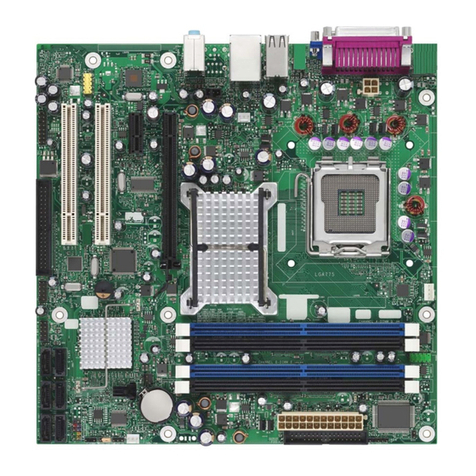
Viglen VIG555M User manual

C O M P U T E R S N E T W O R K S S O L U T I O N S
..
VIG555M
Motherboard
Manual

V1.0 VIG555M Motherboard Manual 1
Viglen, EMC and the ‘CE’ mark
CE Marking
European standards are being harmonised across borders. If products comply with the same standards in all
European countries, product exporting and importing is made simple - paving our way to a common market. If
you buy a product with a 'CE' mark on it (shown below), on the box, in the manual, or on the guarantee - it
complies with the currently enforced directive(s).
Introduction to EMC
EMC (Electromagnetic Compatibility) is the term used to describe certain issues with RF (Radio Frequency)
energy. Electrical items should be designed so they do not interfere with each other through RF emissions. E.g.
If you turn on your microwave, your television shouldn't display interference if both items are CE marked to the
EMC directive.
If emitted RF energy is not kept low, it can interfere with other electrical circuitry - E.g. Cars Automatic Braking
Systems have been known to activate by themselves while in a strong RF field. As this has obvious
repercussions ALL electrical products likely to cause RF related problems have to be 'CE' marked from 1st
January 1996 onwards.
If a product conforms to the EMC directive, not only should its RF emissions be very low, but its immunity to RF
energy (and other types) should be high. The apparatus has to resist many 'real world' phenomena such as
static shocks and mains voltage transients.
Viglen’s Environment laboratory
To gain a 'CE' mark, the Viglen computer range has had to undergo many difficult tests to ensure it is
Electromagnetically Compatible. These are carried out in the in-house 'Environment lab' at Viglen Headquarters.
We have made every effort to guarantee that each computer leaving our factory complies fully with the correct
standards. To ensure the computer system maintains compliance throughout its functional life, it is essential you
follow these guidelines.
¾Install the system according to Viglen’s instructions
¾If you open up your Viglen:
¾Keep internal cabling in place as supplied.
¾Ensure the lid is tightly secured afterwards
¾Do not remove drive bay shields unless installing a 'CE' marked peripheral in its place
¾The clips or ‘bumps' around the lips of the case increase conductivity - do not remove or damage.
¾Do not remove the ferrite ring from the L.E.D cables.
¾Only use your Viglen computer with 'CE' marked peripherals
This system has been tested in accordance with European standards for use in residential and light industrial
areas-this specifies a 10 meter testing radius for emissions and immunity. If you do experience any adverse
affects which you think might be related to your computer, try moving it at least 10 meters away from the affected
item. If you still experience problems, contact Viglen’s Technical Support department who will put you straight
through to an EMC engineer - s/he will do everything possible to help. If modifications are made to your Viglen
computer system, it might breach EMC regulations. Viglen take no responsibility (with regards to EMC
characteristics) of equipment which has been tampered with or modified.
This symbol on the product or on its packaging indicates that the product shall not be treated as
household waste. Instead it shall be handed over to the applicable collection point for recycling of
electrical and electronic equipment. By ensuring this product is disposed of correctly, you will help
prevent potential negative consequences for the environment and human health, which could
otherwise be caused by inappropriate waste handling of this product. The recycling of materials will
help to conserve natural resources. For more detailed information about recycling of this product,
please contact your local city office, your household waste disposal service or Viglen Ltd.
V1.0 VIG555M Motherboard Manual 2
Copyrights and Trademarks
Please note
The material in this manual is subject to change without notice.
Trademarks
Microsoft, Windows, Windows NT, Windows 95,Windows 98, Windows ME,
Windows 2000 Pro, Windows XP Pro and MS-DOS are registered trademarks of
Microsoft Corporation. IBM PC, XT, AT and PS/2 are trademarks of International
Business Machines Corporation. Pentium® and Pentium® Pro are registered
trademarks of Intel® Corporation. All other trademarks are acknowledged. JAC-UP,
Genie, Contender, Dossier, Vig, Viglen, and Envy are trademarks of Viglen Limited.
Copyright and Patents
This manual and all accompanying software and documentation are copyrighted and
all rights reserved. This product, including software and documentation, may not, in
whole or in part, be copied, photocopied, translated or reduced to any electronic or
machine-readable form, without prior written consent except for copies retained by
the purchaser for backup.
© Copyright 2004 Viglen Limited
All Rights Reserved
VIG555M Manual Version 1.0
Printed in the United Kingdom
Liability
No warranty or representation, either expressed or implied, is made with respect to
this documentation, its quality, performance, merchantability or fitness for a particular
purpose. As a result the documentation is licensed as is, and you, the licensee, are
assuming the entire risk as to its quality and performance. The vendor reserves the
right to revise this operation manual and all accompanying software and
documentation and to make changes in the content without obligation to notify any
person or organisation of the revision or change.
In no event will the vendor be liable for direct, indirect, special, incidental or
consequential damages arising out of the use or inability to use this product or
documentation, even if advised of the possibility of such damages. In particular, the
vendor shall not have liability for any hardware, software or data stored or used with
the product, including the costs of repairing, replacing or recovering such hardware,
software or data.

V1.0 VIG555M Motherboard Manual 3
Contents
Chapter 1: Motherboard Overview 5
Introduction 5
Feature Summary 6
System Board Components 14
Overview of System Board Components 15
Back Panel Connectors 18
Chapter 2: System Board Options 20
Overview of Jumper Settings 22
System Board Jumper Settings 23
Motherboard Connectors 25
Front Panel Connectors 26
Upgrading the CPU 27
Installing & Removing Memory Modules 28
Expansion Slots (PCI & AGP) 29
Replacing the Clock/CMOS RAM Battery 30
Chapter 3: Solving Problems 32
Resetting the System 32
Troubleshooting Procedures 33
Problems Operating Add-in Boards 34
Problems & Suggestions 35
Chapter 4: System BIOS 37
What is the BIOS? 38
The Power-On Sequence 38
Phoenix BIOS – Introduction 39
BIOS Upgrades 39
Using AWDFALSH to Update the BIOS 40
Configuring the Motherboard using BIOS Setup 41
BIOS Setup Program 42
BIOS Menu Screen 43
Main Menu 44
Main Menu items 44
Standard CMOS Features 45
Advanced BIOS Features 46

V1.0 VIG555M Motherboard Manual 4
Advanced Chipset Features 48
DRAM Timing Control 50
AGP & P2P Bridge Control 52
OnChip AGP Control 53
VGA Share Memory Size 53
Integrated Peripherals 54
OnChipIDEDevice 54
OnChipPCIDevice 55
Onboard Super I/O Device 57
Onboard PCI Device 57
Power Management Setup 58
PM Wakeup Events 59
PnP/PCI Configurations 60
IRQ Resources 61
PC Health Status 62
Frequency/Voltage Control 63
Main Menu Additional Options 65
Chapter 5: Technical Information 66
Enhanced IDE 66
Operating Systems and Hard Drives 66
Power Supply Connector 68
Other Useful Connectors 68
Other Information 73
Reliability 73
Temperature 73
Chapter 6: Glossary 74
Notes 74
Chapter 7: Suggestions 77

V1.0 VIG555M Motherboard Manual 5
Chapter 1: Motherboard Overview
Introduction
This manual describes the Viglen Vig555M motherboard inside your computer. The
motherboard is the most important part of your computer. It contains all of the CPU,
memory and graphics circuitry that make the computer work.
The motherboard contains the very latest CPU design that supports the Intel®
Pentium® 4 family including Hyper-Threading enabled CPU’s and the very latest
Extreme Edition CPU’s. All of the supported CPU’s include Intel’s® MMX
Technology. MMX technology adds a total of 57 new instructions to the CPU, all of
which are designed to vastly improve both multimedia and communications on your
PC. The combination of the Intel® processor, MMX technology and Viglen expertise
make this a formidable computer.
This manual contains technical information about the Viglen Vig555M motherboard
and other hardware components inside your computer. If you are new to computers
we recommend that you read the user guide first. If you are an experienced
computer user this manual should provide all the information you will need to
perform simple upgrades and maintenance.
We hope that this manual is both readable and informative. If you have any
comments for suggestions about how we could improve the format then please fill
out the form at the back of the manual and send it to us.
Above all we hope that you enjoy using your Viglen computer.

V1.0 VIG555M Motherboard Manual 6
Feature Summary
The Vig555M motherboard supports Intel® Pentium® 4 processors LGA 775 pin with
up to 1MB of second-level cache integrated in a LGA 775 Socket package operating
at speeds up to 3.8GHz. The Celeron processor 775 pin with 128K second-cache
with 400MHz system bus is also supported up to 3.2GHz.
The motherboard features:
Form factor:
•Micro ATX Form Factor: 243mm by 230mm
Processor:
•Single Pentium 4 CPU
•400MHz Quad-pumped bus
•Integrated 256KB second-level cache
•Socket 775 connector.
Main memory:
•Two 184-pin DDR DIMM sockets.
•Support for up to 2GB of DDR DIMM memory.
Chipset
•SiS 661FX
•800Hz Front Side Bus (FSB)
•AGP 8x
•Support for 266/333/400MHz DDR RAM
•Advanced System Power Management features
•Integrated Super I/O Controller
•DirectSound AC97 Audio
•Dual bus master IDE Ultra DMA33/66/100/133
Audio
Audio Codec ’97 (AC ’97) compatible audio subsystem
LAN
Realtek 10/100 Mbit/sec Platform LAN Connect (PLC) device
Peripheral Interfaces
•Support for two internal Universal Serial Bus (USB) ports and four external
•One serial port

V1.0 VIG555M Motherboard Manual 7
•One parallel port
•Two IDE interfaces with Ultra DMA 33, ATA66/100/133 support.
•Two SATA interfaces.
•One diskette drive interface
•PS/2 keyboard and mouse ports
Expansion Capabilities
•Three PCI bus add-in card connectors
•One AGP Pro connector
Instantly Available PC
•Support for PCI Local Bus Specification Revision 2.2
•Suspend to RAM support
•Wake on PS/2 keyboard and USB ports
Wake on LAN Technology Connector
•Support for system wake up using an add-in network interface card with
remote wake up capability
Microprocessor
The motherboard supports a single Pentium 4 processor with HT technology. The
processor’s VID pins automatically program the voltage regulator on the
motherboard to the required processor voltage. In addition, the front side bus speed
is automatically selected. The motherboard currently supports processors that run
internally up to 3.8GHz and have a 1MB second-level cache running at full CPU
Speed.
The processor implements MMX ™ technology and maintains full backward
compatibility with the 8086, 80286, Intel386 ™, Intel486 ™, Pentium, Pentium Pro,
Pentium II & Pentium III processors. The processor’s numeric coprocessor
significantly increases the speed of floating-point operations and complies with
ANSI/IEEE standard 754-1985.
Microprocessor Packaging
The Pentium 4 processor comes in a LGA package that connects to the motherboard
through a socket 775 connector. The package consists of:
•Processor card including the processor core and the second-level cache,
burst pipelined synchronous static RAM (BSRAM) and tag RAM.
•Thermal plate.
•Back cover.

V1.0 VIG555M Motherboard Manual 8
Second Level Cache
The second-level cache is located on the die of the CPU itself. The cache includes
burst pipelined synchronous static RAM (BSRAM) and tag RAM. All supported
onboard memory can be cached.
Processor Upgrades
The motherboard can be upgraded with a Pentium 4 processor that runs at higher
speeds.
Memory
Main Memory
The motherboard has two DDR DIMM sockets. Minimum memory size is 128MB;
maximum memory size is 2GB. The BIOS automatically detects memory type, size,
and speed.
The motherboard supports the following memory features:
•184-pin DIMMs.
•266/333/400Mhz
•Un-Buffered Non-ECC DIMM.
RDRAM
Synchronous DRAM (SDRAM) improves memory performance through memory
access that is synchronous with the memory clock. This simplifies the timing design
and increases memory speed because all timing is dependent on the number of
memory clock cycles.
Chipset
The SiS 661FX chipset is the latest generation of desktop PCI set, it includes new
features such as –
•8x AGP Support
•ATA-133 IDE Hard drive support
•SATA Hard drive support
•800MHz Front Size Bus support
•ACPI & On-Now
Accelerated Graphics Port (AGP)
The Vig555M features both integrated graphics and an AGP port. When using the
integrated graphics then a dynamic portion of the main system memory is used as
video memory. You can also use any AGP video card, with 4x/8x AGP performance.

V1.0 VIG555M Motherboard Manual 9
The Accelerated Graphics Port (AGP) is a high-performance interconnect for
graphic-intensive applications, such as 3D applications. AGP is independent of the
PCI bus and is intended for exclusive use with graphical-display devices. AGP
overcomes certain limitations of the PCI bus related to handling a large amount of
graphics data with the following performance features:
•Pipelined-memory read and write operations that hide memory access
latency.
•Demultiplexing of address and data on the bus for near 100 percent bus
efficiency.
•AC timing for 133 MHz data transfer rates, allowing data throughput of 500
MB/sec.
Realtek 8100C Platform LAN Connect Device
The Realtek 8100C component provides an interface to the back panel RJ-45
connector with integrated LEDs. This physical interface may alternately be provided
via the CNR connector.
The Realtek 8100C provides the following functions:
•Basic 10/100 Ethernet LAN Connectivity
•Supports RJ-45 connector with status indicator LEDs
•Full driver compatibility
•Advanced Power Management support
•Programmable transit threshold
•Configuration EEPROM that contains the MAC address
RJ-45 LAN Connector LEDs
Two LEDs are built into the RJ-45 LAN connector. The following table describes the
LED states when the board is powered up and the LAN subsystem is operating.
Table 1: LAN LED Status
LED Colour LED State Condition
Green Off 10 Mbit/sec data rate is
selected.
Green On 100 Mbit/sec date rate is
selected.
Yellow Off LAN link is not
established.
Yellow On (steady state) LAN link is established.
Yellow On (brighter and pulsing) The computer is
communicating with
another computer on
the LAN.
Universal Serial Bus (USB)
The motherboard has four USB ports and a further four can be added via internal
headers; one USB peripheral can be connected to each port. For more than eight
USB devices, an external hub can be connected to either port. The motherboard
fully supports the universal host controller interface (UHCI) and uses UHCI-
compatible software drivers.

V1.0 VIG555M Motherboard Manual 10
USB features include:
•Self-identifying peripherals that can be plugged in while the computer is
running.
•Automatic mapping of function to driver and configuration.
•Supports isochronous and asynchronous transfer types over the same set of
wires.
•Supports up to 127 physical devices.
•Guaranteed bandwidth and low latencies appropriate for telephony, audio,
and other applications.
•Error-handling and fault-recovery mechanisms built into the protocol.
NOTE: Computer systems that have an unshielded cable attached to a USB port
may not meet FCC Class B requirements, even if no device or a low-speed (sub-
channel) USB device is attached to the cable. Use shielded cable that meets the
requirements for high-speed (fully rated) devices.
IDE Support
The motherboard has two independent bus-mastering PCI IDE interfaces. These
interfaces support PIO Mode 3, PIO Mode 4, ATAPI devices (e.g., CD-ROM), Ultra
DMA/33, Ultra DMA/66, Ultra DMA/100 & Ultra DMA/133 synchronous-DMA mode
transfers. The BIOS supports logical block addressing (LBA) and extended cylinder
head sector (ECHS) translation modes. The BIOS automatically detects the IDE
device transfer rate and translation mode.
Programmed I/O operations usually require a substantial amount of processor
bandwidth. However, in multitasking operating systems, the bandwidth freed by bus
mastering IDE can be devoted to other tasks while disk transfers are occurring.
LS-120 Support
LS-120 MB Diskette technology enables you to store 120MB of data on a single, 3.5”
removable diskette. LS-120 technology is backward (both read and write)
compatible with 1.44MB and 720KB DOS-formatted diskette and is supported by
Windows 95 and Windows NT operating system.
The Vig555M board allows connection of an LS-120 compatible drive and a standard
3½” floppy drive. The LS-120 drive can be configured as a boot device before a
floppy drive, if selected in the BIOS setup utility.
Note:
If you connect an LS-120 drive to an IDE connector and configure it as the “A” drive
and configure a standard 3.5” floppy as “B” drive, the standard floppy must be
connected to the floppy drive cable’s “A” connector (the connector at the end of the
cable).
The BIOS setup utility can be configured to boot firstly from either the LS120 or
standard 3½” floppy drive.

V1.0 VIG555M Motherboard Manual 11
Real-Time Clock, CMOS SRAM, and Battery
The real-time clock is compatible with DS1287 and MC146818 components. The
clock provides a time-of-day clock and a multi-century calendar with alarm features
and century rollover. The real-time clock supports 256 bytes of battery-backed
CMOS SRAM in two banks that are reserved for BIOS use.
The time, date, and CMOS values can be specified in the Setup program. The
CMOS values can be returned to their defaults by using the Setup program.
An external coin-cell (CR 2032) battery powers the real-time clock and CMOS
memory. When the computer is not plugged into a wall socket, the battery has an
estimated life of three years. When the computer is plugged in, the 3.3-V standby
current from the power supply extends the life of the battery. The clock is accurate
to ±13 minutes/year at 25 ºC with 3.3 V applied.
I/O Interface Controller
The motherboard uses the SMC FDC37C777 I/O controller which features:
•Serial ports:
⎯Internal send/receive 16-byte FIFO buffer.
⎯Four internal 8-bit DMA options for the UART with SIR support (USI).
•Multimode bidirectional parallel port:
⎯Standard mode, IBM and Centronics compatible.
⎯Enhanced parallel port (EPP) mode with BIOS and driver support.
⎯High-speed extended capabilities port (ECP) mode.
•Floppy disk controller:
⎯N82077 compatible.
⎯Single diskette drive interface.
⎯16-byte FIFO.
⎯High-performance digital data separator (DDS).
⎯PC-AT and PS/2 drive-mode support.
•Keyboard and mouse controller:
⎯Industry standard 8042A compatible.
⎯General-purpose microcontroller.
⎯8-bit internal data bus.
•ISA Plug-and-Play compatible register set.
•PCI PME interface.
•Intelligent auto power management:
⎯Shadowed write-only registers for ACPI compliance.
⎯Programmable wake up event interface.
By default, the I/O controller interfaces are automatically configured during boot up.
The I/O controller can also be manually configured in the Setup program.
Serial Ports
One 9-pin D-Sub serial port connector is located on the back panel and is compatible
with NS16C550 UARTs.

V1.0 VIG555M Motherboard Manual 12
Parallel Port
The connector for the multimode bidirectional parallel port is a 25-pin D-Sub
connector located on the back panel. In the Setup program, the parallel port can be
configured for the following:
•Compatible (standard mode).
•Bidirectional (PS/2 compatible).
•Extended Parallel Port (EPP).
•Enhanced Capabilities Port (ECP).
Floppy Controller
The I/O controller is software compatible with the N82077 floppy drive controllers
and supports both PC-AT and PS/2 modes. In the Setup program, the floppy
interface can be configured for the following floppy drive capacities and sizes:
•360 KB, 5.25-inch
•1.2 MB, 5.25-inch
•720 KB, 3.5-inch
•1.2 MB, 3.5-inch (driver required)
•1.25/1.44 MB, 3.5-inch
•2.88 MB, 3.5-inch
PS/2 Keyboard and Mouse Interface
PS/2 keyboard and mouse connectors are located on the back panel. The +5 V lines
to these connectors are protected with a PolySwitch circuit that, like a self-healing
fuse, re-establishes the connection after an over-current condition is removed.
The keyboard controller supports the hot-key sequence <Ctrl><Alt><Del> for a
software reset. This key sequence resets the computer’s software by jumping to the
beginning of the BIOS code and running the Power-On Self Test (POST).
Audio Subsystem
The Vig555M board has multiple AC ’97 V 1.03 compliant audio features including
an Analog Devices ALC 655 codec.
The audio subsystem includes these features:
•Split digital/analog architecture for improved S/N (signal-to-noise) ratio: ≥85dB –
measured at line out, from any analog input, including line in, CD-ROM, and
auxiliary line in.
•3-D stereo enhancement
•Power management support for APM 1.2 and ACPI 1.0 (driver dependant)
•Audio inputs:
oFour analog line-level stereo inputs for connection from line in, CD, video
source line in and aux
oTwo analog line-level inputs for speakerphone input and PC beep

V1.0 VIG555M Motherboard Manual 13
oOne mono microphone input
•Audio outputs:
oStereo line-level output
oMono output for speakerphone
Management Extension Component
System BIOS
The system BIOS, from Phoenix Technology, provides ISA and PCI compatibility.
The BIOS is contained in a flash memory device on the system board. The BIOS
provides the power-on self test (POST), the system Set-up program, a PCI and IDE
auto-configuration utility, and BIOS recovery code.
PCI Auto Configuration
The PCI auto-configuration utility works in conjunction with the Set-up program to
support using PCI add-in boards in the system. When you turn on the system power
after installing a PCI board, the BIOS automatically configures interrupts, DMA
channels, I/O space, and so on. Since PCI add-in boards use the same interrupt
resources as ISA add-in boards, you must specify the interrupts used by ISA boards
in the set-up program. The PCI auto-configuration program complies with version 2.1
of the PCI BIOS specification.
IDE Auto Configuration
If you install an IDE drive in the system, the IDE auto-configuration utility
automatically detects and configures the drive for operation in the system. This
utility eliminates the need to enter the Set-up program after you install an IDE drive.
Expansion Slots
The system has two PCI bus add-in card connectors and One AGP universal
connector.

V1.0 VIG555M Motherboard Manual 14
System Board Components
Figure 1: Motherboard Layout & Components
Table 2: Motherboard Connection
A: Serial header P: CPU Fan header
B: Audio header Q: IDE 2
C: Case Fan R: IDE 1
D: BIOS S: CMOS Battery
E: Audio CD in T: SATA 1 and 2
F: Rear Audio U: Power LED and speaker
header
G: LAN and USB V: Front Panel header
H: USB W: Clear CMOS jumper
I: VGA, Serial and Parallel X: Chassis intrusion header
J: PS/2 Keyboard and mouse Y: South Bridge
K: ATX 20 pin Z: USB header 1
L: ATX 4 pin AA: USB header 2
M: North Bridge BB: Floppy connector
N: 775 pin CPU socket CC: PCI slots
O: DIMM socket 1 and 2 DD: I/O chip

V1.0 VIG555M Motherboard Manual 15
Overview of System Board Components
A – Serial Header
Allows a serial device to be attached.
B – Audio Header
Allows a front audio panel to be connected. (Intel®Standard)
C – Case Fan Header
Allows a case fan to be connected to aid cooling.
D – BIOS
This controls the boot loader and all the hardware in the system.
E – Rear Audio
Allows a MIC, a Line-in and a Line-out to be connected.
F – Front Panel Audio
Allows a front facing audio panel to be fitted.
G – LAN and USB
Allows up to four USB devices to be connected and a network.
H – VGA, Serial and Parallel
Allows a VGA monitor, a serial device and a parallel device to be attached.
I – PS/2 Keyboard and mouse
Allows a PS/2 Keyboard and mouse to be attached.
K – 20 pin ATX power connector
This is the main power connector for the motherboard.
L – 4 pin ATX power connector
This provides power directly to the CPU and to the AGP port.
M – North Bridge
The SIS ® 611FX provides the processor interface with 800/533/400 MHz frequency,
support for Intel ® Hyper-Threading Technology, system memory interface at

V1.0 VIG555M Motherboard Manual 16
266MHz operation, and 1.5V AGP interface that supports AGP 2.0 specification
including 8x Fast Write protocol.
N – 775 pin CPU Socket
This is were the CPU is installed.
O – DIMM slots 1 and 2.
This allows up to 2GB of DDR RAM to be installed. Up to 1GB of RAM in each slot.
P – CPU Fan header
Allows a CPU fan to be connected
Q – Second IDE
This allows an additional 2 IDE device to be added to the motherboard. The port is
slotted to ensure correct installation.
R – Primary IDE
This allows up to 2 devices, such as CD/DVD drives and hard drives to be added
to the IDE channel. The port is slotted to ensure correct installation.
S – CMOS Battery
Supplies backup power to the CMOS. This keeps all the settings and information in
the BIOS.
T – SATA 0 and 1
This allows two SATA devices to be connected.
U – Power LED and speaker header.
This allows a three pin power LED and a speaker to be connected to the board.
V – Front Panel header
This allows the case cables to be connected, such as HDD LED, Reset switch and
power switch.
W – Clear CMOS jumper
Moving the jumper from the default position allows the CMOS to be cleared and
reset.

V1.0 VIG555M Motherboard Manual 17
X – Chassis intrusion
Allows a chassis intrusion switch to be added.
Y – South Bridge
The SIS®964L integrated peripheral controller supports various I/O functions
including 2-channel ATA/133 bus master IDE controller, up to six USB 2.0 ports,
LPC Super I/O interface, AC’97 interface and PCI 2.2 interface.
Z – USB Header 1
This allows up to two USB devices to be connected though the use of a cable.
AA – USB Header 2
This allows an addition two USB devices to be connected though the use if a cable.
BB – Floppy Connector
Allows a floppy drive to be connected
CC – PCI slots
Allows two PCI devices to be connected to the board.
DD – I/O chip
This controls the Input and the Output on the motherboard

V1.0 VIG555M Motherboard Manual 18
Back Panel Connectors
The motherboard external IO connectors are attached to a metallic I/O shield. This
shield serves several purposes:
•It protects the sensitive motherboard from any external EMC interference.
•It stops the computer from interfering with other electrical devices.
•It allows the motherboard to be easily upgraded in the future without having to
resort to buying a whole new case. Simply change the I/O shield to match the
motherboard.
The I/O shield provides external access to PS/2 keyboard and mouse connectors as
well as one serial port, one parallel port, four USB ports, one LAN Port and the audio
connectors.
Figure 2: Rear I/O Shield
NOTE: Power to the computer should be turned off before a keyboard or mouse is
connected or disconnected.
A/B – PS/2 Keyboard/Mouse Ports
The purple connector is for a PS/2 keyboard and the green connector is for a PS/2
mouse connector.
C – Serial Port
This 9-pin COM1 port is for a pointing device or other serial devices.
D – Parallel Port
This 25-pin port allows connection of a parallel device e.g. Printer, scanner etc
E –Video Graphics Adapter Port
This 15-pin port is for a VGA monitor or other VGA-compatible devices.

V1.0 VIG555M Motherboard Manual 19
F – USB 2.0 Ports
These 4-pin Universal Serial Bus (USB) ports are available for connecting USB 2.0
devices.
G – RJ-45 Port
This port allows connection to a Local Area Network (LAN) through a network hub.
H – Line-In Jack
This Line In (light blue) jack connects a tape player or other audio sources. In 6-
channel mode, the function of this jack becomes Bass/Center.
I – Line-Out Jack
This Line Out (lime) jack connects a headphone or a speaker. In 6-channel mode,
the function of this jack becomes Front Speaker Out.
J – Microphone Jack
This Mic (pink) jack connects a microphone. In 6-channel mode, the function of this
jack becomes Rear Speaker Out.
NOTE: The functions of the Line Out, Line In, and Microphone jacks change
when you select the 6-channel audio configuration.
Table 3: Audio 2, 4 or 6-channel configuration
Headphone/2-
Speaker 4-Speaker 6-Speaker
Light Blue Line In Rear Speaker
Out
Rear Speaker
Out
Lime Line Out Front Speaker
Out
Front Speaker
Out
Pink Mic In Mic In Bass/Center
Table of contents
Other Viglen Motherboard manuals

Viglen
Viglen Vig711W User manual

Viglen
Viglen D915GHA User manual

Viglen
Viglen Vig710W User manual

Viglen
Viglen Vig580s User manual

Viglen
Viglen D865GLC User manual

Viglen
Viglen PMPGF001 User manual

Viglen
Viglen Vig660W User manual

Viglen
Viglen Vig870G User manual

Viglen
Viglen VIG556M User manual

Viglen
Viglen EQ100 User manual

Viglen
Viglen Vig680M User manual

Viglen
Viglen CX135 User manual

Viglen
Viglen Vig430p User manual

Viglen
Viglen L440GX+ User manual

Viglen
Viglen Vig535b User manual

Viglen
Viglen Vig750s Technical manual

Viglen
Viglen Vig770S User manual

Viglen
Viglen Vig103M User manual

Viglen
Viglen Vig550B User manual

Viglen
Viglen Vig440J User manual