Viking VGSB5152 User manual

Viking Range Corporation
111 Front Street
Greenwood, Mississippi 38930 USA
(662) 455-1200
For product information,
call 1-888-VIKING1 (845-4641)
or visit the Viking Web site at
vikingrange.com
F20921 EN (000000)
Viking Installation Guide
Outdoor 15” Wide Double Side Burners

GAS CONNECTION
Verify the type of gas supply to be used, either natural or LP, and make sure the marking on the rating plate agrees
with that of the supply. Never connect an unregulated gas line to the appliance. An installer supplied gas shut-off
valve must be installed in an easily accessible location. All installer supplied parts must conform to local codes, or in
the absence of local codes, with the National electrical Code, ANSI/NFPA 70 and the National Fuel Code, ANSI
Z223.1. In Canada: Installation must be in accordance with the current CAN/CGA-B149.1, Natural Gas Installation
Code or CAN/CGA-B149.2, Propane Installation Code and/or local codes. All pipe sealants must be an approved type
and resistant to the actions of LP gas. Never use pipe sealant on flare fittings. All gas connections should be made by
a competent technician and in accordance with local codes and or ordinances. In the absence of codes, the installation
must comply with the National Fuel Gas Code ANSI Z223.1.
The gas side burner and its individual shut-off valve must be disconnected from the gas supply piping system during
any pressure testing of that system at test pressures in excess of 1/2 PSIG (3.5 kPa). The unit must be isolated from the
gas supply piping system by closing its individual manual shut-off valve during any pressure testing of that system at
test pressures equal to or less than 1/2 psi (3.5 kPa).
Built-in installations must be plumbed using a fixed/hard line if the unit is going to be operated at a
distance exceeding 3 feet (0.91 meters) from the fuel supply per ANSI Z21.24.
3
BASIC SPECIFICATIONS
IMPORTANT:PLEASE READANDFOLLOW
1. Before beginning, please read these instructions completely and carefully.
2. Do not remove permanently affixed labels, warnings, or plates from product. This may void the warranty
3. Please observe all local and national codes and ordinances.
4. The installer should leave these instructions with the consumer who should retain for local inspector’s use and for
future reference
Installation must conform with local codes or in the absence of codes, the National Fuel Gas Code, ANSI Z223.1.
In Canada: Installation must be in accordance with the current CAN/CGA-B149.1, Natural Gas Installation Code or
CAN/CGA-B149.2, Propane Installation Code and/or local codes.
If you smell gas:
1. Shut off gas to the appliance.
2. Extinguish any open flame.
3. Open lid.
4. If odor continues, immediately call your gas supplier or your
fire department.
1. Do not store or use gasoline or other flammable vapors
and liquids in the vicinity of this or any other appliance.
2. Any LP cylinder not connected for use shall not be stored
in the vicinity of this or any other appliance.
If not installed, operated and maintained in
accordance with the manufacturer’s instructions, this
product could expose you to substances in fuel or
fuel combustion which can cause death or serious
illness and which are known to cause cancer, birth
defects or other reproductive harm.
For example, benzene is a chemical which is
part of the gas supplied to the cooking
product. It is consumed in the flame during
combustion. However, exposure to a small
amount of benzene is possible if a gas leak
occurs. Formaldehyde and soot are by-
products of incomplete combustion. Properly
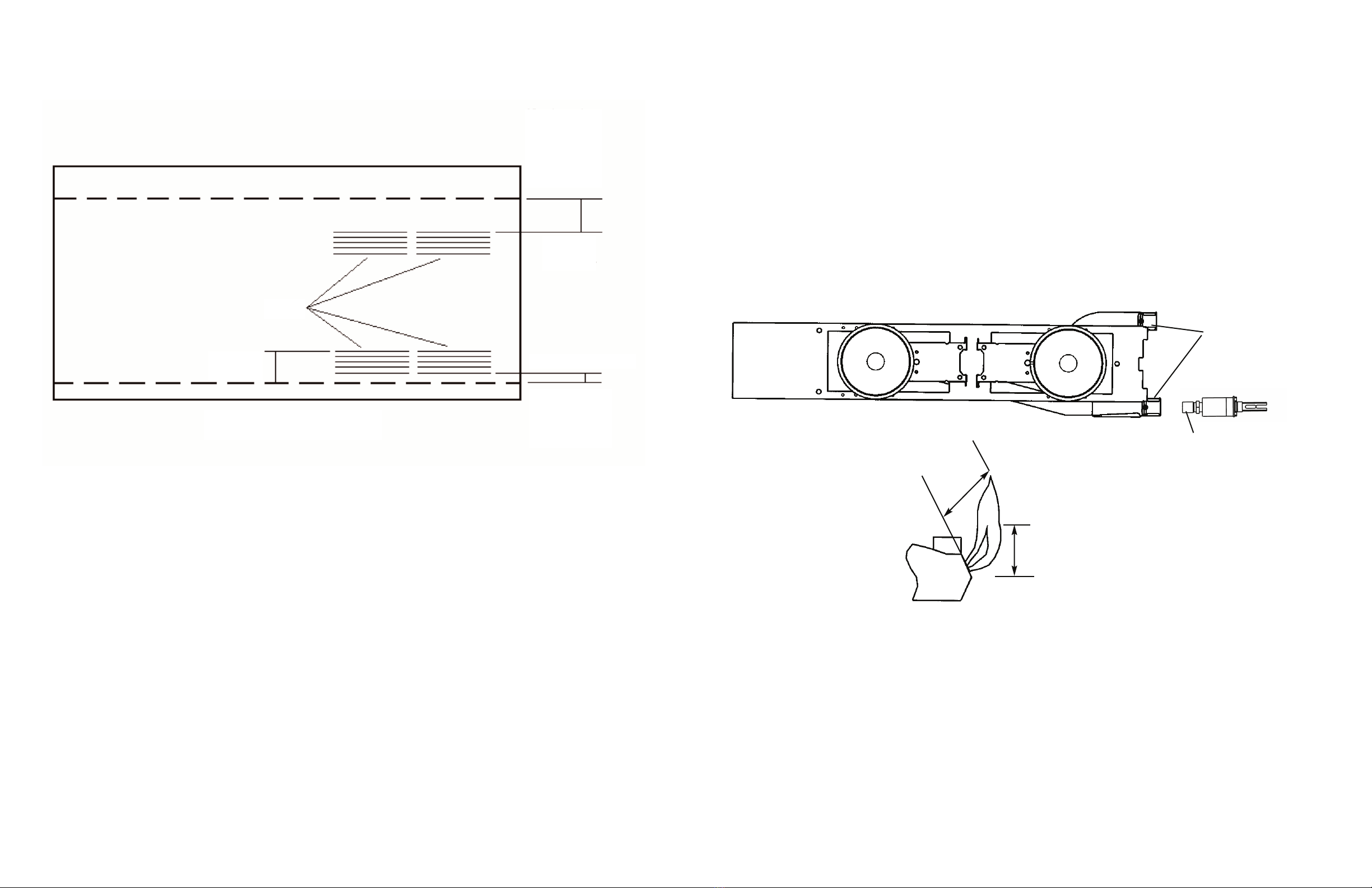
adjusted burners with a bluish rather than
yellow flame minimize incomplete combustion.
2
FOR YOUR SAFETY WARNING
FOR YOUR SAFETY
GENERAL INFORMATION
WARNING:This outdoor gas side burner is not intended to be installed in or on recreational vehicles
and/or boats.
WARNING: Keep electrical supply cord and the fuel supply hose away from heated surfaces.
• Keep area clear and free from combustible materials, gasoline, and other flammable vapors.
• When the outdoor gas side burner or grill is not in use, the gas supply must be turned off at the LP gas supply
cylinder.
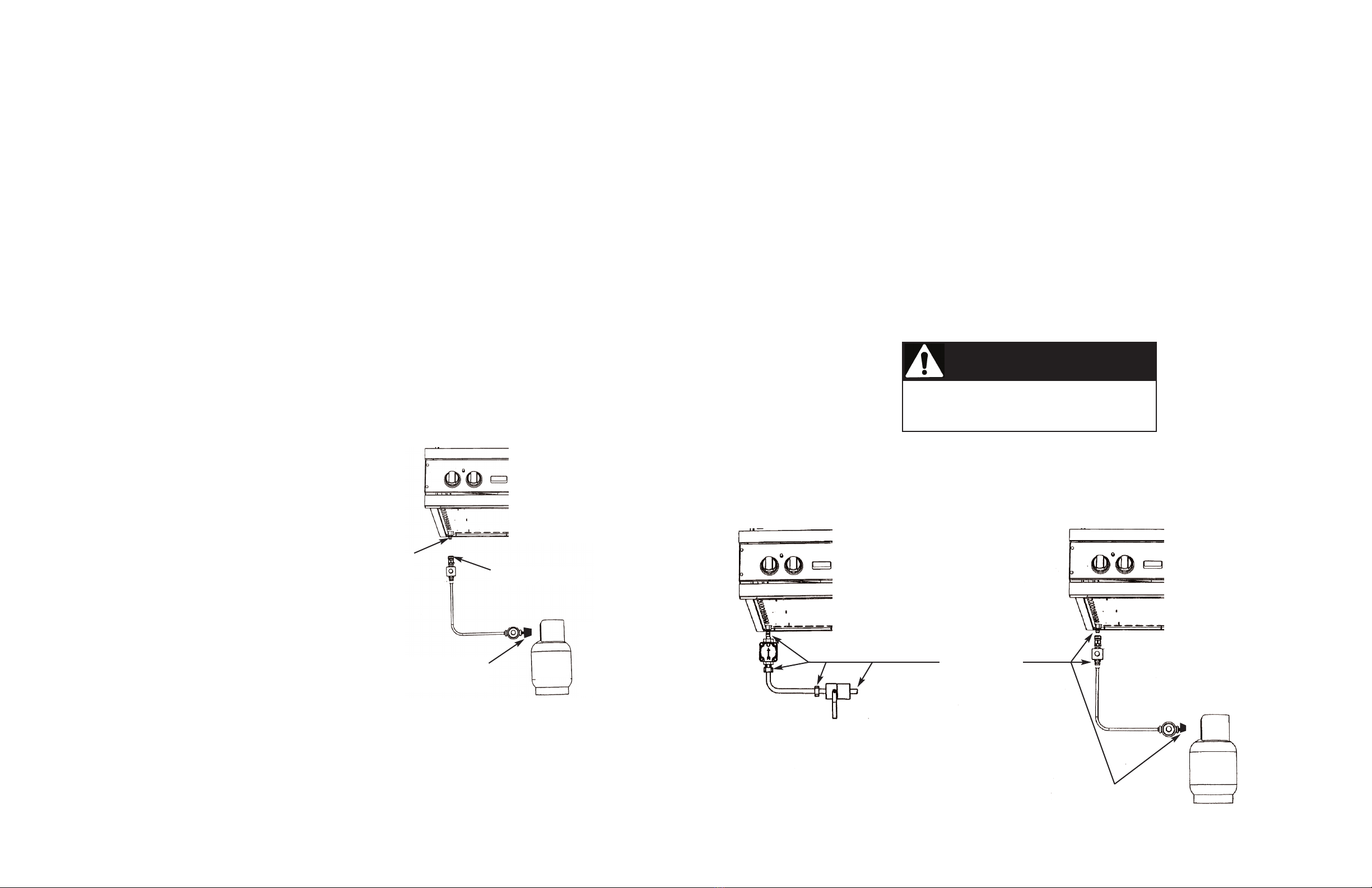
• The pressure regulator and hose assembly supplied with the unit must be used. Replacement pressure regulators
and hose assemblies must be those specified by the manufacturer.
• Finding a leak is not a “do-it-yourself” procedure. Some leaks can only be found with the burner control in the on
position and this must be done by a qualified technician.
• The LP supply cylinder to be used must be constructed and marked in accordance with the specifications for LP-
gas cylinders of the U.S. Department of Transportation (DOT) or the National Standard of Canada, CAN/CSA-
B339, Cylinders, Spheres, and Tubes for the Transportation of Dangerous Goods.
• Gas Manifold Pressure -
Natural gas - 4.0” W.C.P.
LP/Propane - 10.0” W.C.P.
• If the following instructions are not followed exactly, a fire causing death or serious injury may occur:
-Do not store a spare LP gas cylinder under or near this appliance.
-Never fill the cylinder beyond 80 percent full.
SAFETY TIPS
•Keep outdoor cooking appliance area free from combustible materials, gasoline and other flammable vapors and
liquids.
•Keep ventilation openings at the rear of the cart and cylinder free and clear to allow proper air flow. Do not obstruct
the flow of combustion and ventilation air.
•Spiders and insects can nest in the burners of the grill and block the gas and air flow to the burner ports. This may
cause a fire from behind the manifold cover. Inspect and clean burners periodically.
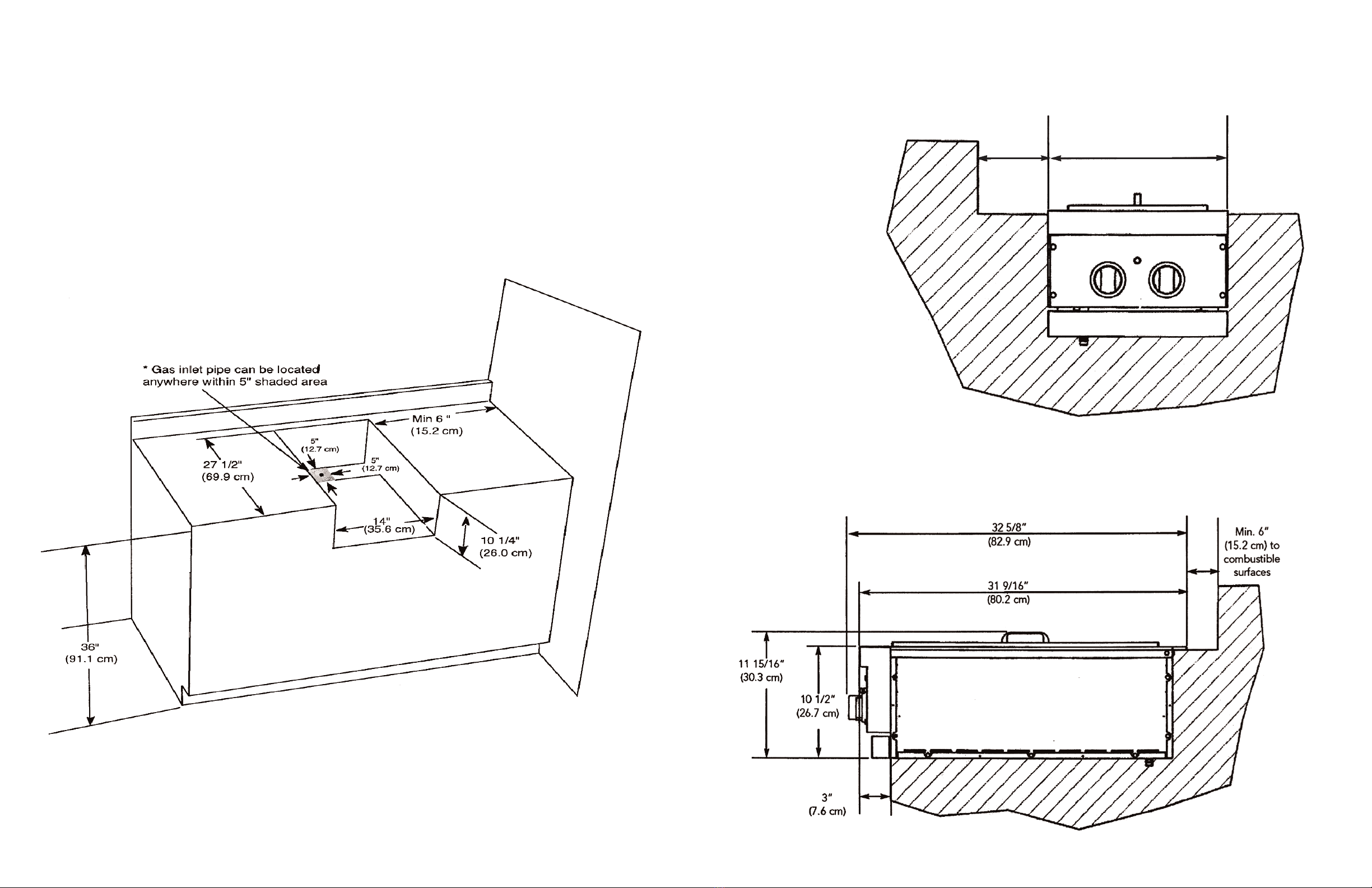
DescriptionVGSB5152
Overall Width 15-5/16” (38.9 cm)
Overall Depth To end of landing ledge 31-9/16” (80.2 cm)
To end of knobs 32-5/8” (82.9 cm)
Overall Height To cooking surface 10 1/2” (26.3 cm)
Cutout Width 14 ” (35.6 cm)
Cutout Depth 27-1/2” (69.9 cm)
Cutout Height 10-1/4” (26.0 cm)
Gas Requirements Natural: standard residential 1/2” (1.3 cm) ID gas service line.
LP/Propane: equipped with high capacity hose/regulator assembly for connection
to standard 5 gal, 20 lb. LP/Propane gas cylinder with Type 1, QCC-1
connection or standard residential 1/2” (1.3 cm) ID gas service line.
Side Burner Rating (2) - 15,000 BTU Nat./13,500 BTU LP
(4.4 kW Nat./4.0 kW LP)
Approximate Shipping Wt. 80 lbs. (36.3 kg) 55 lbs. (24.8 kg)

3/8” female
flare adaptor
Regulator
3/8” male
flare adaptor
Regulator Assembly
3/8” Male
flare
adaptor
Installer supplied flexible
gas line with 3/8”
female flare adaptor or
Viking GHS12
Regulator Assembly
Female
coupler sleeve
Regulator
1/2” male
flare adaptor
Male
coupler
fitting
Installer supplied flexible
gas line with 1/2”
female flare adaptor or
Viking GHS12
LP/PROPANE FIXED PIPING CONNECTION
Connection: Standard Residential 1/2” ID gas service line - 1/2” NPT male with 3/8” flare adapter.
Operating Pressure: 10.0” W.C.P. Nat.
Supply Pressure: 11” to 14” W.C.P. Nat. If in excess of 14” W.C.P., a step-down regulator is required.
Check with your local gas utility company or with local codes for instructions on installing gas supply lines. Be sure to check on
type and size of run and how deep to bury the lines. If the gas line is too small, the unit will not function properly.
To connect the supplied regulator assembly to the incoming flexible gas line, attach with a 3/8” female flare adaptor to the
3/8” male flare adaptor to the regulator assembly. Ensure that the regulator arrow points in the direction of the gas flow
towards the unit and away from the supply. Attach the regulator assembly to the unit with the 3/8” female flare adapter on the
regulator assembly to the 3/8” male flare adaptor on the unit.
DO NOT forget to place the installer supplied gas valve in an accessible location.
NATURAL FIXED PIPING CONNECTION
Connection: Standard Residential 1/2” ID gas service line - 1/2” NPT male with 1/2” flare adapter.
Operating Pressure: 4.0” W.C.P. Nat.
Supply Pressure: 6” to 14” W.C.P. Nat. If in excess of 14” W.C.P., a step-down regulator is required.
Check with your local gas utility company or with local codes for instructions on installing gas supply lines. Be sure to check on
type and size of run and how deep to bury the lines. If the gas line is too small, the unit will not function properly.
To connect the supplied regulator assembly to the incoming flexible gas line, attach with a 1/2” (1.3 cm) female flare adaptor
to the 1/2” (1.3 cm) male flare adaptor on the regulator assembly. Ensure that the regulator arrow points in the direction of the
gas flow towards the unit and away from the supply. Attach the regulator assembly to the unit by pulling back the female
coupler sleeve towards the regulator. Insert the coupler into the male coupler fitting on the grill until the sleeve snaps forward
securing the connection. DO NOT forget to place the installer supplied gas valve in an accessible location.
NOTE:If using a Viking GSH12 flexible hose,remove the 3/8” flare adapter and attach hose to the the 1/2” (1.3 cm) male
flare on the regulator assembly.
5
4

LEAK TESTING
Although all gas connections on the unit are leak tested at the factory prior to shipment, a complete gas tightness check must
be performed at the installation due to possible mishandling in shipment or excessive pressure unknowingly being applied to
the unit. Periodically check the whole system for leaks, or immediately check if the smell of gas is detected.
1. Do not smoke while leak testing. Extinguish all flames.
2. Never leak test with an open flame.
3. Make a soap solution of one part liquid detergent and one part water. You will need a spray bottle, brush or towel to apply
the solution to the fittings. For LP/Propane units, check with a full cylinder.
4. Check that all control knobs are in the “OFF” position.
5. Turn cylinder valve knob counter clockwise one turn to open.
6. Blowing bubbles in the soap solution indicates that a leak is present.
7. Stop a leak by tightening the loose joint or by replacing the faulty part with a replacement part recommended by the
manufacturer. Do not attempt to repair the cylinder valve if it should become damaged. The cylinder must be replaced.
8. If you are unable to stop a leak, shut off the gas supply at the cylinder valve. Remove the cylinder from the unit. Call an
authorized gas appliance service technician or LP/Propane gas dealer. Do not use the unit until the leak is corrected.
9. After checking for leaks, push in and turn any control knob to release the pressure in the hose and manifold. Turn off the
control knob.
LEAK TEST
POINTS
Tank
3/8” flare
adaptor
Type 1, QCC-1
connector Tank
3/8” flare coupling
7
6
LP/PropaneTank Connection
Outdoor side burners orificed for use with LP/Propane gas come equipped with a high capacity hose/regulator assembly
for connection to a standard 20 lb. LP/Propane cylinder equipped with a Type 1, QCC-1 connector. (See LP/Propane tank
requirements on page 6). Hose assembly must comply with Elastomeric Composite Hose and Couplings for Conducting
Propane and Natural Gas, CAN/CGA-8.1 standard or the Thermoplastic Hose and Hose Couplings for Conducting
Propane and Natural Gas CAN1-8.3 standard. (See LP/Propane tank requirements below). Each tank is supplied with a
dust cap. Place dust cap on cylinder valve outlet whenever the cylinder is not in use. Only install the type of dust cap on
the cylinder valve outlet that is provided with the cylinder valve. Other types of caps or plugs may result in leakage of
propane.
Built-in installations must be plumbed using a fixed/hard line if the unit is going to be operated at a distance exceeding
3 feet (0.91 meters) from the fuel supply per ANSI Z21.24. Also, in a built-in construction where an LP/Propane tank is
going to be used, there MUST be some type of support (braces, cut-out, etc.) to prevent tank from moving within the
installation. The support must also allow the LP/Propane tank to withstand a horizontal tipping force equal to the weight
of the tank without tipping over. The tank can not tip over or deflect more than 1.00 inch when a 38 lb. horizontal force
is applied to a 20 lb. LP/Propane tank.
Connection: 1/2” (1.3 cm) NPT male with a 3/8” (.95) flare adapter
Operating Pressure: 10.0” W.C.P.
To connect to LP/Propane regulator/hose assembly:
Although the flow of gas is stopped when the quick disconnect system is disconnected as part of its safety feature, you
should always turn the LP/Propane tank main valve “OFF” after each use and during transport of the tank or unit. First
connect the regulator to the unit by screwing the 3/8” flare coupling to the 3/8” flare adapter. Connect to the tank valve
by screwing the Type 1, QCC-1 connector to the LP/Propane tank. Open the tank valve and check the connection
between the regulator and the Type 1, QCC-1 fitting for leaks with a soapy water solution. If bubbles appear, tighten the
connection. Repeat until all leaks have been stopped. ALWAYS CHECK FOR LEAKS AFTEREVERY LP/PROPANE TANK
CHANGE.Any joint sealant used must be an approved type and be resistive to the actions of LP/Propane gas.
LP/PropaneTank Requirements
A dented or rusty LP/Propane tank may be hazardous and
should be checked by your tank supplier. Never use a cylinder
with a damaged valve. All tanks should be equipped with an
OPD (overfilling protection device). This is a DOT requirement
for all tanks purchased after October 1, 1998 and will ensure
that the tank is not overfilled. The LP/Propane tank should be
a standard 5-gal, 20 lb. gas cylinder tank approximately 12” in
diameter and 18” high which must be constructed and marked
in accordance with the Specifications for LP/Propane Gas
Cylinders of the U.S. Department of Transportation (D.O.T.) or
the National Standard of Canada, CAN/CSA-B339, Cylinders,
Spheres and Tubes for Transportation of Dangerous Goods; and
Commission. The cylinder connection device must be
compatible with the Type 1, QCC-1 connector on the outdoor
cooking appliance. All LP/Propane tanks must be mounted in a
vertical position for proper ventilation. The cylinder must be
provided with a shut-off valve terminating in an LP/Propane gas
supply cylinder valve outlet specified. The cylinder supply
system must be arranged for vapor withdrawal and provided
with a listed overfilling prevention device. If the appliance is
stored indoors the cylinder must be disconnected and removed
from the appliance. Each tank is supplied with a dust cap. Place
dust cap on cylinder valve outlet whenever the cylinder is not in
use. Only install the type of dust cap on the cylinder valve outlet
that is provided with the cylinder valve. Other types of caps or
plugs may result in leakage of propane. Cylinders must be
stored outdoors in a well-vented area out of the reach of
children.
*Tank must be
mounted in
vertical position
for proper
ventilation
Before placing into operation, always check for gas
leaks with a soapy water solution. DO NOT USE AN
OPEN FLAME TO CHECK FOR LEAKS!
CAUTION
*Tank must be
mounted in
vertical position
for proper
ventilation

Built-In Clearance Dimensions – VGSB5152
Front ViewMin. 6”
(15.2 cm)
to
combustible
surfaces
15 5/16”
(38.9 cm)
INSTALLATION PROCEDURES FOR BUILT-IN INSTALLATION
1. A minimum of 6” (15.2 cm) from the sides must be maintained from the side burners above the cooking surface to adjacent
vertical combustible construction. The unit is not to be located under overhead unprotected combustible construction.
2. It is desirable to allow at least 6” side clearance to non-combustible construction above the cooking surface for counter
space.
3. When determining a suitable location for the unit, take into account concerns such as exposure to wind, proximity to traffic
paths and keeping gas supply lines as short as possible. Locate only in a well-ventilated area. Never locate in a building,
garage, breezeway, shed or other such enclosed areas.
4. In a built-in construction where an LP/Propane tank is going to be used, there MUST be some type of support (braces, cut-
out, etc.) to prevent tank from moving within the installation. The support must also allow the LP/Propane tank to withstand
a horizontal tipping force equal to the weight of the tank without tipping over. The tank can not tip over or deflect more
than 1.00 inch when a 38 lb. horizontal force is applied to a 20 lb. LP/Propane tank.
IMPORTANT:Gas fittings, regulator, and installer supplied shut-off valve must be easily accessible.
9
8
Side View

BURNERADJUSTMENT– VGSB5152
Each burner is tested and adjusted at the factory prior to shipment; however, variations in the local gas supply may make it
necessary to adjust the burners. The flames of the burners should be visually checked and compared with flame height
illustration.
Flames should be blue and stable with no yellow tips, excessive noise or lifting. If any of these conditions exist, check if the air
shutter or burner ports are blocked by dirt, debris, spider webs, etc. With a proper flame height, adjust the air shutter to
obtain a blue flame with no yellow tipping that sits on the burner at the burner ports. The air shutter is locked in place by a set
screw which must be loosened prior to lighting the burner for adjustments.
To access the air shutter on the side burners, remove the grates, burner bowls, and grate support. With a screw driver, loosen
the lock-screw on the face of the air shutter. Light the burner and adjust according to the directions below.
1. If the flame is yellow, turn the air shutter counter clockwise to allow more air to the burner.
2. If the flame is noisy and lifting away from the burner, turn the air shutter clockwise to reduce the amount of air to
the burner.
Once adjusted, turn the burner off, tighten the set screw on the air shutter, replace the valve panel for the side burners and the
grate support, burner bowls, and grates for the side burners.
To ensure proper installation of the side burners, slide opening in air shutters over the orifice located in the front of the unit.
11
Air Shutters
Orifice
1½”
(3.8 cm)
3/8”
(.95 cm)
FLAME HEIGHT
1. At least one ventilation opening shall be provided on the exposed exterior side of the enclosure located within 5
inches (127 mm) of the top of the enclosure and unobstructed. The opening(s) shall have a total free area of not
less than 1 in2/lb (14.2 cm2/kg) of stored fuel capacity.
2. At least one ventilation opening shall be provided on the exposed, exterior side of the enclosure 1 inch (25.4 mm)
or less from the floor level and shall have a total free area of not less than 1/2 in2/lb (7.1 cm2/kg) of stored fuel
capacity. The upper edge shall be no more than 5 inches (127 mm) above the floor level.
3. Every opening shall have a minimum dimension so as to permit the entrance of a 1/8 inch (3.2 mm) rod.
VENTILATION FOR BUILT-IN INSTALLATIONS
Not less than
5.00 inches
from inside
bottom of
countertop.
Not less than
1.00 inch from
inside floor of
installation.
1.00 inch maximum
5.00 inch
maximum
No more than 5.00 inches above
the floor of the installation.
5.00 inch
maximum
Vents
10

13
CLEANING AND MAINTENANCE
Any piece of equipment works better and lasts longer when maintained properly and kept clean. Grilling equipment is
no exception. Your TruSear™ Infrared Burner must be kept clean and maintained properly.
TruSear InfraredGrill Burner
When finished cooking, turn the control knob to the “HI” setting and allow the burner to burn for Five Minutes. This
helps to eliminate any drippings or debris that would otherwise remain on the burner, degrading the performance and
reducing burner life. After the five minute burn-off time, turn the grill OFF and allow to cool completely before
attempting to clean or move. Wipe excess grease and food from grill surfaces.
NOTE:When the TruSear infrared griller is not use, it must be covered with the provided stainless steel cover for protection from outside
elements such as rain.
•Do not use a metal knife or any other metal tool to scrape stainless steel parts.
•Do not permit citrus or tomato juice to remain on stainless steel surfaces, as citric acid will
permanently discolor stainless steel. Wipe up any spills immediately.
•Do not use abrasive cleaners, steel wool pads, or abrasive cloths on stainless steel, painted parts or
brass parts.
•Do not use brass cleaners on the brass option parts. They are coated with an epoxy coating.
*Under rare conditions, such as an extremely salty environment, small amounts of rust may accumulate on stainless steel
parts. These small amounts of surface rust can easily be removed by applying Soft Scrub® Gel to a damp sponge and
wiping with the stainless steel grain. It is important to make sure you wipe with the grain for the most efficient removal
of surface rust.
Stainless Steel*Parts
Some stainless steel parts may have a plastic protective wrap which must be peeled off. Do not expose protective plastic
film on the stainless steel to heat or direct sunlight. It could melt onto the stainless steel parts and become difficult to
remove. The interior should be washed thoroughly with hot, soapy water to remove film residues and any dust or debris
before being used, then rinsed and wiped dry. Solutions stronger than soap and water are rarely needed.
All stainless steel body parts should be wiped with hot, soapy water and with a liquid cleaner designed for this material.
If buildup occurs, do not use steel wool, abrasive cloths, cleansers, or powders! If it is necessary to scrape stainless steel
to remove encrusted materials, soak with hot, wet cloths to loosen the material, then use a wool or nylon scraper. Do not
use a metal knife, spatula, or any other material tool to scrape stainless steel! Scratches are almost impossible to remove.
REPLACEMENT PARTS
Only authorized replacement parts may be used in performing service on the side burners. Do not repair or replace any
part of the outdoor grill unless specifically recommended in the manual. All other servicing should be referred to a
qualified technician.
CAUTION
Drip Tray
The drip tray pans should be removed and cleaned after each use. Allow the drippings in the drip tray pans to cool
completely before removing. To remove the drip tray pans, simply remove the pans from the tray. Place the trays in hot,
soapy water to clean. Wipe up any debris that may have collected in the drip tray with a hot, soapy towel. Dry and
replace drip tray pans before next use.
PERFORMANCE CHECKLIST
A qualified installer should carry out the following checks:
1. All internal packaging removed.
2. Specified clearances maintained to combustible materials.
3. Pressure regulator connected and set.
4. Manual shut-off valve installed and accessible.
5. Check air shutter adjustment - sharp blue flame, no yellow tipping.
6. Check for gas leaks (odors) at all gas connections.
7. Each burner lights satisfactory, individually or with adjacent burners lit.
Any adjustments necessary that are the result of the installer not following instructions will be responsibility of the installer,
dealer or the end user of the product.
FINALPREPARATION
1. Some stainless steel parts may have a plastic protective wrap which must be peeled off. The interior should be washed
thoroughly with hot, soapy water to remove film residues and any dust or debris before being used, then rinsed and wiped
dry. Solutions stronger than soap and water are rarely needed.
2. All stainless steel body parts should be wiped with hot, soapy water and with a liquid cleaner designed for this material. If
buildup occurs, do not use steel wool, abrasive cloths, cleansers, or powders! If it is necessary to scrape stainless steel to
remove encrusted materials, soak with hot, wet cloths to loosen the material, then use a wool or nylon scraper. Do not use
a metal knife, spatula, or any other material tool to scrape stainless steel! Scratches are almost impossible to remove.
12

15
PROFESSIONALSERIES
OUTDOOR BUILT-IN DOUBLE SIDE BURNER WARRANTY
ONE YEARFULL WARRANTY
Built-in outdoor double side burner and TruSear Infrared Grillers and all of their component parts, except as detailed below*, are warranted to be free
from defective materials or workmanship in normal household use for a period of twelve (12) months from the date of original retail purchase. Viking
Range Corporation, warrantor, agrees to repair or replace, at its option, any part which fails or is found to be defective during the warranty period.
*Painted, porcelain, and decorative items are warranted to be free from defective materials or workmanship for a period of ninety (90) days from the date
of original retail purchase. ANY DEFECTS MUST BE REPORTED TO THE SELLING DEALER WITHIN NINETY (90) DAYS FROM DATE OF ORIGINAL
RETAIL PURCHASE.
Viking Range Corporation uses the most up-to-date processes and best materials available to produce all color finishes. However, slight color variation
may be noticed because of the inherent differences in painted parts and porcelain parts as well as differences in kitchen lighting, product locations, and
other factors.
FIVE YEAR LIMITED WARRANTY
Any double side burner or TruSear infrared burner which fails due to defective materials or workmanship in normal household use during the second
through fifth year from the date of original retail purchase will be repaired or replaced, free of charge for the part itself, with the owner paying all other
costs, including labor.
LIFETIME LIMITED WARRANTY
Any stainless steel part (see 90-day porcelain provision above*), which rusts through due to defective materials or workmanship in normal household use
during the second through the useful lifetime of the unit from the date of original retail purchase will be repaired or replaced, free of charge for the part
itself, with the owner paying all other costs, including labor.
NINETY (90) DAY RESIDENTIALPLUS WARRANTY This warranty applies to applications where use of the product extends beyond normal
residential use. Examples are, but not limited to, bed and breakfasts, fire stations, private clubs, churches, etc. This warranty excludes all
commercial locations such as restaurants, food service locations and institutional food service locations.
This warranty extends to the original purchaser of the product warranted hereunder and to each transferee owner of the product during the term of the
warranty.
This warranty shall apply to products purchased and located in the United States and Canada. Products must be purchased in the country where service
is requested. Warranty labor shall be performed by an authorized Viking Range Corporation service agency or representative. Warranty shall not apply to
damage resulting from abuse, accident, natural disaster, loss of electrical power to the product for any reason, alteration, improper installation, improper
operation, or repair or service of the product by anyone other than an authorized Viking Range Corporation service agency or representative. This
warranty does not apply to commercial usage. Warrantor is not responsible for consequential or incidental damage whether arising out of breach of
warranty, breach of contract, or otherwise. Some jurisdictions do not allow the exclusion or limitation of incidental or consequential damages, so the
above limitation or exclusion may not apply to you.
Owner shall be responsible for proper installation, providing normal care and maintenance, providing proof of purchase upon request, and making the
appliance reasonably accessible for service. If the product or one of its component parts contains a defect or malfunction during the warranty period,
after a reasonable number of attempts by the warrantor to remedy the defects or malfunctions, the owner is entitled to either a refund or replacement of
the product or its component part or parts. Warrantor’s liability on any claim of any kind, with respect to the goods or services covered hereunder, shall in
no case exceed the price of the goods or service or part thereof which gives rise to the claim.
WARRANTY SERVICE: Under the terms of this warranty, service must be performed by a factory authorized Viking Range Corporation service agent or
representative. Service will be provided during normal business hours, and labor performed at overtime or premium rates shall not be covered by this
warranty. To obtain warranty service, contact the dealer from whom the product was purchased, an authorized Viking Range Corporation service agent, or
Viking Range Corporation. Provide model and serial number and date of original purchase. For the name of your nearest authorized Viking Range
Corporation service agency, call the dealer from whom the product was purchased or Viking Range Corporation. IMPORTANT: Retain proof of original
purchase to establish warranty period.
The return of the Owner Registration Card is not a condition of warranty coverage. You should, however, return the Owner Registration Card so that
Viking Range Corporation can contact you should any question of safety arise which could affect you.
Any implied warranties of merchantability and fitness applicable to the above described TruSear infrared burner and stainless steel parts are limited in
duration to the period of coverage of the applicable express written limited warranties set forth above. Some jurisdictions do not allow limitations on how
long an implied warranty lasts, so the above limitation may not apply to you. This warranty gives you specific legal rights, and you may also have other
rights which may vary from jurisdiction to jurisdiction.
Specifications subject to change without notice.
14
SERVICE INFORMATION
If service is required:
1. Call your dealer or authorized service agency. The name of the authorized service agency can be
obtained from the dealer or distributor in your area.
2. Have the following information readily available:
a. Model number
b. Serial number
c. Date purchased
d. Name of dealer from whom purchased
3. Clearly describe the problem that you are having.
If you are unable to obtain the name of an authorized service agency, or if you continue to have service problems,
contact Viking at (888) 845-4641 or write to:
VIKING PREFERRED SERVICE
111 Front Street
Greenwood, Mississippi 38930 USA
Record the information indicated below. You will need it if service is ever required. The model and serial number
for your grill is located on an identification plate located under the drip tray in the rear left corner next to the inlet
pipe.
Model Number Serial Number
Date of Purchase Date Installed
Dealer’s Name
Address
KEEP THIS MANUAL FORFUTURE REFERENCE.

1716
This manual suits for next models
1
Table of contents
Other Viking Burner manuals
Popular Burner manuals by other brands

Riello
Riello RDB2.2 GKD Installation, use and maintenance instructions

Bentone
Bentone BFG 1 H2 Biogas Installation and maintenance instruction

Riello
Riello RG4F Installation, use and maintenance instructions

baltur
baltur TBG 1600 LX ME Instruction manual for installation, use and maintenance

Hauck
Hauck MegaStar MS-50 instructions

Oilon
Oilon GKP-350 M Operation and maintenance manual