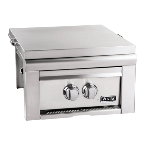
Viking VGSB5153 Technical manual

Viking Range, LLC
111 Front Street
Greenwoo , Mississippi 38930 USA
(662) 455-1200
For pro uct information,
call 1-888-(845-4641)
or visit the Viking website at
vikingrange.com
F21363 EN (120913)
Viking Use/Installation Gui e
Out oor 15” Wi e Double Si e Burners

Gas Connection
Verify the type of gas supply to be use , either natural or LP, an make sure the marking on the rating plate agrees
with that of the supply. Never connect an unregulate gas line to the appliance. An installer supplie gas shut-off
valve must be installe in an easily accessible location. All installer supplie parts must conform to local co es, or in
the absence of local co es, with the National electrical Co e, ANSI/NFPA 70 an the National Fuel Co e, ANSI
Z223.1. IInn CCaannaaaa:: Installation must be in accor ance with the current CAN/CGA-B149.1, Natural Gas Installation
Co e or CAN/CGA-B149.2, Propane Installation Co e an /or local co es. All pipe sealants must be an approve type
an resistant to the actions of LP gas. Never use pipe sealant on flare fittings. All gas connections shoul be ma e by
a competent technician an in accor ance with local co es an or or inances. In the absence of co es, the installation
must comply with the National Fuel Gas Co e ANSI Z223.1.
The gas si e burner an its in ivi ual shut-off valve must be isconnecte from the gas supply piping system uring
any pressure testing of that system at test pressures in excess of 1/2 PSIG (3.5 kPa). The unit must be isolate from the
gas supply piping system by closing its in ivi ual manual shut-off valve uring any pressure testing of that system at
test pressures equal to or less than 1/2 psi (3.5 kPa).
BBuuiilltt--iinn iinnssttaallllaattiioonnss mmuusstt bbee pplluummbbee uussiinngg aa ffiixxee//hhaarr lliinnee iiff tthhee uunniitt iiss ggooiinngg ttoo bbee ooppeerraattee aatt aa
iissttaannccee eexxcceeeeiinngg 33 ffeeeett ((00..9911 mmeetteerrss)) ffrroomm tthhee ffuueell ssuuppppllyy ppeerr AANNSSII ZZ2211..2244.. AAllll ccoonnnneeccttoorrss nneeee
ttoo ccoommppllyy wwiitthh AANNSSII ZZ2211..7755// CCSSAA 66..2277.. WWhheenn uussiinngg sseemmii--rriiggee ttuubbiinngg,, aalluummiinnuumm oorr aalluummiinnuumm aallllooyy
ttuubbiinngg iiss nnoott ppeerrmmiittttee.. AAllll ccoonnnneeccttiioonnss aarree ttoo bbee vviissiibbllee tthhrroouugghh oooorr oorr ooppeenniinngg iinn tthhee eenncclloossuurree..
3
BBAASSIICC SSPPEECCIIFFIICCAATTIIOONNSS
Important: Please Rea an Follow
1. Before beginning, please rea these instructions completely an carefully.
2. Do not remove permanently affixe labels, warnings, or plates from pro uct. This may voi the warranty
3. Please observe all local an national co es an or inances.
4. The installer shoul leave these instructions with the consumer who shoul retain for local inspector’s use an for
future reference
Installation must conform with local co es or in the absence of co es, the National Fuel Gas Co e, ANSI Z223.1.
IInn CCaannaaaa::Installation must be in accor ance with the current CAN/CGA-B149.1, Natural Gas Installation Co e or
CAN/CGA-B149.2, Propane Installation Co e an /or local co es.
IIff yyoouu ssmmeellll ggaass::
11.. SShhuutt ooffff ggaass ttoo tthhee aapppplliiaannccee..
22.. EExxttiinngguuiisshh aannyy ooppeenn ffllaammee..
33.. OOppeenn llii..
44.. IIff oooorr ccoonnttiinnuueess,, iimmmmeeiiaatteellyy ccaallll yyoouurr ggaass ssuupppplliieerr oorr yyoouurr
ffiirree eeppaarrttmmeenntt..
11.. DDoo nnoott ssttoorree oorr uussee ggaassoolliinnee oorr ootthheerr ffllaammmmaabbllee vvaappoorrss
aann lliiqquuiiss iinn tthhee vviicciinniittyy ooff tthhiiss oorr aannyy ootthheerr aapppplliiaannccee..
22.. AAnnyy LLPP ccyylliinneerr nnoott ccoonnnneeccttee ffoorr uussee sshhaallll nnoott bbee ssttoorree
iinn tthhee vviicciinniittyy ooff tthhiiss oorr aannyy ootthheerr aapppplliiaannccee..
If not installe , operate an maintaine in
accor ance with the mmaannuuffaaccttuurreerr’’ss instructions, this
pro uct coul expose you to substances in fuel or
fuel combustion which can cause eath or serious
illness an which are known to cause cancer, birth
efects or other repro uctive harm.
For example, benzene is a chemical which is
part of the gas supplie to the cooking
pro uct. It is consume in the flame uring
combustion. However, exposure to a small
amount of benzene is possible if a gas leak
occurs. Formal ehy e an soot are by-
pro ucts of incomplete combustion. Properly
a juste burners with a bluish rather than
yellow flame minimize incomplete combustion.
2
FOR YOUR SAFETY WARNING
FOR YOUR SAFETY
General Information
WWAARRNNIINNGG: This out oor gas si e burner is not inten e to be installe in or on recreational vehicles
an /or boats.
WWAARRNNIINNGG:: Keep electrical supply cor an the fuel supply hose away from heate surfaces.
• Keep area clear an free from combustible materials, gasoline, an other flammable vapors.
• When the out oor gas si e burner or grill is not in use, the gas supply must be turne off at the LP gas supply
cylin er.
• The pressure regulator an hose assembly supplie with the unit must be use . Replacement pressure regulators
an hose assemblies must be those specifie by the manufacturer.
• Fin ing a leak is not a “ o-it-yourself” proce ure. Some leaks can only be foun with the burner control in the on
position an this must be one by a qualifie technician.
• The LP supply cylin er to be use must be constructe an marke in accor ance with the specifications for LP-
gas cylin ers of the U.S. Department of Transportation (DOT) or the National Stan ar of Cana a, CAN/CSA-
B339, Cylin ers, Spheres, an Tubes for the Transportation of Dangerous Goo s.
• Gas Manifol Pressure -
Natural gas - 4.0” W.C.P.
LP/Propane - 10.0” W.C.P.
• If the following instructions are not followe exactly, a fire causing eath or serious injury may occur:
-Do not store a spare LP gas cylin er un er or near this appliance.
-Never fill the cylin er beyon 80 percent full.
Safety Tips
•Keep out oor cooking appliance area free from combustible materials, gasoline an other flammable vapors an
liqui s.
•Keep ventilation openings at the rear of the cart an cylin er free an clear to allow proper air flow. Do not obstruct
the flow of combustion an ventilation air.
•Spi ers an insects can nest in the burners of the grill an block the gas an air flow to the burner ports. This may
cause a fire from behin the manifol cover. Inspect an clean burners perio ically.
DDeessccrriippttiioonnVVGGSSBB55115533
Overall Wi th 15-5/16” (38.9 cm)
Overall Depth To en of lan ing le ge 31-9/16” (80.2 cm)
To en of knobs 32-5/8” (82.9 cm)
Overall Height To cooking surface 10 1/2” (26.3 cm)
Cutout Wi th 14 ” (35.6 cm)
Cutout Depth 27-1/2” (69.9 cm)
Cutout Height 10-1/4” (26.0 cm)
Gas Requirements Natural: stan ar resi ential 1/2” (1.3 cm) ID gas service line.
LP/Propane: equippe with high capacity hose/regulator assembly for connection
to stan ar 5 gal, 20 lb. LP/Propane gas cylin er with Type 1, QCC-1
connection or stan ar resi ential 1/2” (1.3 cm) ID gas service line.
12 V - (8 AA batteries)
Electrical Requirements
Si e Burner Rating (2) - 15,000 BTU Nat./13,500 BTU LP
(4.4 kW Nat./4.0 kW LP)
Approximate Shipping Wt. 80 lbs. (36.3 kg)

3/8”3/8”
malemale
flareflare
dapterdapter
Installer supplied
flexible gas line
with 3/8” female
adapter
Installer supplied
shut-off valve must
be easily accessible
Regulator
Assembly
3/8” male
flare
adapter
MaleMale
couplercoupler
3/8”3/8”
malemale
flareflare
dapterdapter
1/2”
NPT
from
Manifold
MaleMale
couplercoupler
Installer supplied
flexible gas line
with 1/2” female
adapter or GHS12
Installer supplied
shut-off valve must
be easily accessible
7/8” male
flare adapter
Regulator
Assembly
3/8”3/8”
malemale
flareflare
dapterdapter
1/2”
NPT
from
Manifold
LP/PROPANE Fixe Piping Connection
Connection: Stan ar Resi ential 1/2” ID gas service line - 1/2” NPT male with 3/8” flare a apter.
Operating Pressure: 10.0” W.C.P. LP
Supply Pressure: 11” to 14” W.C.P. LP. If in excess of 14” W.C.P., a step- own regulator is require .
Check with your local gas utility company or with local co es for instructions on installing gas supply lines. Be sure to check on
type an size of run an how eep to bury the lines. If the gas line is too small, the unit will not function properly.
To connect the supplie regulator assembly to the incoming flexible gas line, attach with a 3/8” female flare a aptor to the
3/8” male flare a aptor to the regulator assembly. Ensure that the regulator arrow points in the irection of the gas flow
towar s the unit an away from the supply. Attach the regulator assembly to the unit with the 3/8” female flare a apter on the
regulator assembly to the 3/8” male flare a aptor on the unit. All connectors nee to comply with ANSI Z21.75/ CSA 6.27.
When using semi-ri ge tubing, aluminum or aluminum alloy tubing is not permitte .
DDOO NNOOTT ffoorrggeett ttoo ppllaaccee tthhee iinnssttaalllleerr ssuupppplliiee ggaass vvaallvvee iinn aann aacccceessssiibbllee llooccaattiioonn..
Natural Fixe Piping Connection
Connection: Stan ar Resi ential 1/2” ID gas service line - 1/2” NPT male.
Operating Pressure: 4.0” W.C.P. Nat.
Supply Pressure: 6” to 10” W.C.P. Nat. If in excess of 10” W.C.P., a step- own regulator is require .
Check with your local gas utility company or with local co es for instructions on installing gas supply lines. Be sure to check on
type an size of run an how eep to bury the lines. If the gas line is too small, the unit will not function properly.
To connect the supplie regulator assembly to the incoming flexible gas line, attach with a 7/8” (2.2 cm) female flare a aptor
to the 7/8” (2.2 cm) male flare a aptor on the regulator assembly. Ensure that the regulator arrow points in the irection of the
gas flow towar s the unit an away from the supply. Connect the regulator assembly to the grill unit. All connectors nee to
comply with ANSI Z21.75/ CSA 6.27. When using semi-ri ge tubing, aluminum or aluminum alloy tubing is not permitte .
DDOO NNOOTT ffoorrggeett ttoo ppllaaccee tthhee iinnssttaalllleerr ssuupppplliiee ggaass vvaallvvee iinn aann aacccceessssiibbllee llooccaattiioonn..
NNOOTTEE:: IIff uussiinngg aa VViikkiinngg GGSSHH1122 fflleexxiibbllee hhoossee,, rreemmoovvee tthhee 11//22”” ffllaarree aaaapptteerr aann aattttaacchh hhoossee ttoo tthhee tthhee 77//88”” ((22..22 ccmm)) mmaallee
ffllaarree oonn tthhee rreegguullaattoorr aasssseemmbbllyy..
5
4

7
6
LP/Propane Tank Connection
Out oor si e burners orifice for use with LP/Propane gas come equippe with a high capacity hose/regulator assembly
for connection to a stan ar 20 lb. LP/Propane cylin er eeqquuiippppee wwiitthh aa TTyyppee 11,, QQCCCC--11 ccoonnnneeccttoorr..(See LP/Propane tank
requirements on page 6). Hose assembly must comply with Elastomeric Composite Hose an Couplings for Con ucting
Propane an Natural Gas, CAN/CGA-8.1 stan ar or the Thermoplastic Hose an Hose Couplings for Con ucting
Propane an Natural Gas CAN1-8.3 stan ar . (See LP/Propane tank requirements below). Each tank is supplie with a
ust cap. Place ust cap on cylin er valve outlet whenever the cylin er is not in use. Only install the type of ust cap on
the cylin er valve outlet that is provi e with the cylin er valve. Other types of caps or plugs may result in leakage of
propane.
Built-in installations must be plumbe using a fixe /har line if the unit is going to be operate at a istance excee ing
3 feet (0.91 meters) from the fuel supply per ANSI Z21.24. Also, in a built-in construction where an LP/Propane tank is
going to be use , there MUST be some type of support (braces, cut-out, etc.) to prevent tank from moving within the
installation. The support must also allow the LP/Propane tank to withstan a horizontal tipping force equal to the weight
of the tank without tipping over. The tank can not tip over or eflect more than 1.00 inch when a 38 lb. horizontal force
is applie to a 20 lb. LP/Propane tank.
Connection: 1/2” (1.3 cm) NPT male with a 3/8” (.95) flare a apter
Operating Pressure: 10.0” W.C.P.
To connect to LP/Propane regulator/hose assembly:
You shoul always turn the LP/Propane tank main valve “OFF” after each use an uring transport of the tank or unit.
First connect the regulator assembly to the grill unit. Connect to the tank valve by screwing the Type 1, QCC-1 connector
to the LP/Propane tank. Open the tank valve an check the connection between the regulator an the Type 1, QCC-1
fitting for leaks with a soapy water solution. If bubbles appear, tighten the connection. Repeat until all leaks have been
stoppe . AALLWWAAYYSS CCHHEECCKK FFOORR LLEEAAKKSS AAFFTTEERR EEVVEERRYY LLPP//PPRROOPPAANNEE TTAANNKK CCHHAANNGGEE.. AAnnyy jjooiinntt sseeaallaanntt uussee mmuusstt bbee aann
aapppprroovvee ttyyppee aann bbee rreessiissttiivvee ttoo tthhee aaccttiioonnss ooff LLPP//PPrrooppaannee ggaass..
LP/Propane Tank
Requirements
A ente or rusty LP/Propane tank may be hazar ous
an shoul be checke by your tank supplier. Never
use a cylin er with a amage valve. All tanks shoul
be equippe with an OPD (overfilling protection
evice). This is a DOT requirement for all tanks
purchase after October 1, 1998 an will ensure that
the tank is not overfille . The LP/Propane tank shoul
be a stan ar 5-gal, 20 lb. gas cylin er tank
approximately 12” in iameter an 18” high which
must be constructe an marke in accor ance with
the Specifications for LP/Propane Gas Cylin ers of the
U.S. Department of Transportation (D.O.T.) or the
National Stan ar of Cana a, CAN/CSA-B339,
Cylin ers, Spheres an Tubes for Transportation of
Dangerous Goo s; an Commission. The cylin er
connection evice must be compatible with the Type 1,
QCC-1 connector on the out oor cooking appliance.
All LP/Propane tanks must be mounte in a vertical
position for proper ventilation. The cylin er must be
provi e with a shut-off valve terminating in an
LP/Propane gas supply cylin er valve outlet specifie .
The cylin er supply system must be arrange for vapor
with rawal an provi e with a liste overfilling
prevention evice. If the appliance is store in oors the cylin er must be isconnecte an remove from the appliance. Each
tank is supplie with a ust cap. Place ust cap on cylin er valve outlet whenever the cylin er is not in use. Only install the
type of ust cap on the cylin er valve outlet that is provi e with the cylin er valve. Other types of caps or plugs may result in
leakage of propane. Cylin ers must be store out oors in a well-vente area out of the reach of chil ren.
3/8”3/8”
malemale
flareflare
adapteradapter
1/2”
NPT
from
Manifold
Type 1,
QCC-1
connector
3/8” male
flare adapter
Regulator
Assembly
NOTE: Tank must be
mounted in vertical position
for proper Ventilation
Leak Testing
Although all gas connections on the grill are leak teste at the factory prior to shipment, a complete gas tightness check must be
performe at the installation ue to possible mishan ling in shipment or excessive pressure unknowingly being applie to the unit.
Perio ically check the whole system for leaks, or imme iately check if the smell of gas is etecte .
• Do not smoke while leak testing.
• Extinguish all flames.
• Never leak test with an open flame
WARNING
DANGER
CAUTION
FOR YOUR SAFETY
Befo e placing into ope ation, always check fo
gas leaks with a soapy wate solution. DO NOT
USE AN OPEN FLAME TO CHECK FOR LEAKS.
1
OFF
2
Make a soap solution of one part liqui etergent an
one part water. You will nee a spray bottle, brush or
towel to apply the solution to the fittings.
Note: For LP/Propane units, check with a full c linder.
Check that all control knobs are in the “OFF” position.
4
Apply the soap solution to fittings. Turn cylin er valve knob counter clockwise one
turn to open.
3

Built-In Installation
1. A minimum of 6” (15.2 cm) from the si es must be maintaine from the si e burners above the cooking surface to a jacent
vertical combustible construction. The unit is not to be locate un er overhea unprotecte combustible construction.
2. It is esirable to allow at least 6” si e clearance to non-combustible construction above the cooking surface for counter
space.
3. When etermining a suitable location for the unit, take into account concerns such as exposure to win , proximity to traffic
paths an keeping gas supply lines as short as possible. Locate only in a well-ventilate area. Never locate in a buil ing,
garage, breezeway, she or other such enclose areas.
4. In a built-in construction where an LP/Propane tank is going to be use , there MUST be some type of support (braces, cut-
out, etc.) to prevent tank from moving within the installation. The support must also allow the LP/Propane tank to withstan
a horizontal tipping force equal to the weight of the tank without tipping over. The tank can not tip over or eflect more
than 1.00 inch when a 38 lb. horizontal force is applie to a 20 lb. LP/Propane tank.
IIMMPPOORRTTAANNTT:: GGaass ffiittttiinnggss,, rreegguullaattoorr,, aann iinnssttaalllleerr ssuupppplliiee sshhuutt--ooffff vvaallvvee mmuusstt bbee eeaassiillyy aacccceessssiibbllee..
10-1/4”
(26.0 cm)
36”
(91.4 cm)
27-1/2”
(69.9 cm)
14”
(35.6 cm)
*Solid bottom
support
Countertop typically
requires 1/2” wide by 1/2”
deep notch cutout on each
side of grill. This allows grill
Control Panel to sit back
properly in the cutout.
6” min
(15.2 cm
)
Gas inlet
location area
5”
(12.7 cm)
5”
(12.7 cm)
1/2”
(1.2 cm)
1/2”
(1.2 cm)
8
8
5
6
Bubbling bubbles in the soap solution in icates that a
leak is present.
Stop a leak by tightening the loose joint or by
replacing the faulty part with a replacement part
recommen e by the manufacturer.
7
2
8
1
Do not attempt to repair the cylin er valve if it shoul
become amage . The cylin er must be replace .
If you are unable to stop a leak, shut off the gas
at the cylin er valve. Remove the cylin er from the grill.
Call an authorized gas
appliance service technician
or LP/Propane gas dealer.
Do not use the grill until
the leak is corrected.
1
2
9
After checking for leaks, push in an turn any control
knob to release the pressure in the hose an manifol .
Turn off the control knob.
Cutout Dimensions

Ventilation for Built-In Installations
11
Built-In Clearance Dimensions – VGSB5153
FFrroonntt VViieewwMin. 6”
(15.2 cm)
to
combustible
surfaces
15 5/16”
(38.9 cm)
9
SSiiee VViieeww
An enclosure for an LP-gas cylin er shall be ventilate by openings at both the upper an lower levels of the
enclosure. The effectiveness of the opening(s) for purposes of ventilation shall be etermine with the LP-gas supply
cylin er in place. This shall be accompanie by one of the following:
a. One si e of the enclosure shall be completely open; or
b. For an enclosure having four si es, a top an a bottom:
1. At least two ventilation openings shall be provi e in the si e walls of the enclosure, locate within 5 in. (217 mm)
of the top of the enclosure, equally size , space at a minimum of 90 egrees (1.57 ra ), an unobstructe . The
opening(s) shall have a total free area of not less than 1 in2/lb (14.22 cm2/kg) of store fuel capacity.
2. Ventilation opening(s) shall be provi e at floor level at rear of the enclosure an shall have a total free area of not
less than 1/2 in2/lb (7.1 cm2/kg) of store fuel capacity. The bottom of the openings shall be 1 in. (25.4 mm) or less
from the floor level an the upper e ge no more than 5 in. (127 mm) above the floor level. The openings shall
be equally size , space at a minimum of 90 egrees (1.57 ra ) an unobstructe .
3. Every opening shall have minimum imensions so as to permit the entrance of a 1/8 inch (3.2 mm) iameter ro .
4. Ventilation openings in the si e walls shall not communicate irectly with other enclosures of the out oor cooking
gas appliance.
Note: It is strongl recommended to follow the same ventilation requirements when using Natural Gas.
Vents
1.00 inch maximum
5.00 inch
maximum
All vents no more than 5.00 inches
above the floor of the installation.
5.00 inch
maximum
Not more than 5.00
inches from inside
bottom of countertop.
Bottom Vent not
more than 1.00 inch
from inside floor of
installation.
Vents located
on sidewall

Performance Checklist
A qualifie installer shoul carry out the following checks:
1. All internal packaging remove .
2. Specifie clearances maintaine to combustible materials.
3. Pressure regulator connecte an set.
4. Manual shut-off valve installe an accessible.
5. Check air shutter a justment - sharp blue flame, no yellow tipping.
6. Check for gas leaks (o ors) at all gas connections.
7. Each burner lights satisfactory, in ivi ually or with a jacent burners lit.
Any a justments necessary that are the result of the installer not following instructions will be responsibility of the installer,
ealer or the en user of the pro uct.
Final Preparation
1. Some stainless steel parts may have a plastic protective wrap which must be peele off. The interior shoul be
washe thoroughly with hot, soapy water to remove film resi ues an any ust or ebris before being use , then
rinse an wipe ry. Solutions stronger than soap an water are rarely nee e .
2. All stainless steel bo y parts shoul be wipe with hot, soapy water an with a liqui cleaner esigne for this
material. If buil up occurs, o not use steel wool, abrasive cloths, cleansers, or pow ers! If it is necessary to scrape
stainless steel to remove encruste materials, soak with hot, wet cloths to loosen the material, then use a wool or
nylon scraper. Do not use a metal knife, spatula, or any other material tool to scrape stainless steel! Scratches are
almost impossible to remove.
13
Before Lighting Si e Burners
Prior to turning on the gas, inspect the gas supply tubing or
hose. Look for evi ence of abrasion, cuts, wear an tear, or
other amage which coul require replacement prior to use.
Make sure all burner control knobs are off. Do not attempt to
light the burners if the smell of gas is present.
Check the connection with a soap an water solution after
attaching the hose. Make sure there is gas in the tank an the
tank is upright.
WARNING
DANGER
CAUTION
FOR YOUR SAFETY
Wait at least five minutes before relighting a hot grill
to allow any accumulate gas to issipate. Keep a
spray bottle of soapy water near the gas supply valve
an check the connections for gas leaks before each
use.
Lighting Si e Burners
First, remove the burner cover or any cooking utensil
from the burner grate.
Push an turn the control knob until the “HIGH” position aligns with the in icator line on the control panel.
Immediately press the electronic ignition button corresponding to the burner(s) being lit until the
burner is lit or until 4 seconds pass. If the burner does not light after several attempts, wait five
minutes to allow any accumulated gas to dissipate. If the burner will not light after several attempts, then
the burner can be lit by hol ing a lit match next to the burner ports. Push an turn the control knob until the
“HIGH” position on the knob aligns with the in icator line on the control panel.
Burner A justment
Each burner is teste an a juste at the factory prior to shipment; however, variations in the local gas supply may make it
necessary to a just the burners. The flames of the burners shoul be visually checke an compare with flame height
illustration.
Flames shoul be blue an stable with no yellow tips, excessive noise or lifting. If any of these con itions exist, check if the air
shutter or burner ports are blocke by irt, ebris, spi er webs, etc. With a proper flame height, a just the air shutter to
obtain a blue flame with no yellow tipping that sits on the burner at the burner ports. The air shutter is locke in place by a set
screw which must be loosene prior to lighting the burner for a justments.
To access the air shutter on the si e burners, remove the grates, burner bowls, an grate support. With a screw river, loosen
the lock-screw on the face of the air shutter. Light the burner an a just accor ing to the irections below.
1. If the flame is yellow, turn the air shutter counter clockwise to allow more air to the burner.
2. If the flame is noisy an lifting away from the burner, turn the air shutter clockwise to re uce the amount of air to
the burner.
Once a juste , turn the burner off, tighten the set screw on the air shutter, replace the valve panel for the si e burners an the
grate support, burner bowls, an grates for the si e burners.
To ensure proper installation of the si e burners, sli e opening in air shutters over the orifice locate in the front of the unit.
12
Air Shutters
Orifice
1”
(3.8 cm)
3/8”
(.95 cm)
FFLLAAMMEE HHEEIIGGHHTT
WARNING
DANGER
CAUTION
FOR YOUR SAFETY
The si e burner cover may be hot if the grill burners
are in operation.

15
14
Remove the grates, burner bowls. Remove the
top pan by lifting upwards to disengage.
The battery pack will be located on the front right
side interior of the unit.
Loosen the head screws to remove the lid which
is connected to 8 AA batteries.
After replacing the batteries, reattach the lid with
the screws.
Replace the pan, burner bowls and grates.
Note: Please be environmentally-conscious & dispose of old batteries properly.
Replacing Batttery Pack:
Remove the grates, burner bowls. Remove the
top pan by lifting upwards to disengage.
The battery pack will be located on the front right
side interior of the unit.
Loosen the head screws to remove the lid which
is connected to 8 AA batteries.
After replacing the batteries, reattach the lid with
the screws.
Replace the pan, burner bowls and grates.
Note: Please be environmentally-conscious & dispose of old batteries properly.

17
Cleaning an Maintenance
Any piece of equipment works better an lasts longer when maintaine properly an kept clean. Out oor equipment is
no exception. Your si e burner must be kept clean an maintaine properly.
•Do not use a metal knife or any other metal tool to scrape stainless steel parts.
•Do not permit citrus or tomato juice to remain on stainless steel surfaces, as citric aci will
permanently iscolor stainless steel. Wipe up any spills imme iately.
•Do not use abrasive cleaners, steel wool pa s, or abrasive cloths on stainless steel parts.
*Un er rare con itions, such as an extremely salty environment, small amounts of rust may accumulate on stainless steel
parts. These small amounts of surface rust can easily be remove by applying Soft Scrub® Gel to a amp sponge an
wiping with the stainless steel grain. It is important to make sure you wipe with the grain for the most efficient removal
of surface rust.
SSttaaiinnlleessss SStteeeell** PPaarrttss
Some stainless steel parts may have a plastic protective wrap which must be peele off. Do not expose protective plastic
film on the stainless steel to heat or irect sunlight. It coul melt onto the stainless steel parts an become ifficult to
remove. The interior shoul be washe thoroughly with hot, soapy water to remove film resi ues an any ust or ebris
before being use , then rinse an wipe ry. Solutions stronger than soap an water are rarely nee e .
All stainless steel parts shoul be wipe with hot, soapy water an with a liqui cleaner esigne for this material. If
buil up occurs, o not use steel wool, abrasive cloths, cleansers, or pow ers! If it is necessary to scrape stainless steel to
remove encruste materials, soak with hot, wet cloths to loosen the material, then use a wool or nylon scraper. Do not use
a metal knife, spatula, or any other material tool to scrape stainless steel! Scratches are almost impossible to remove.
Replacement Parts
Only authorize replacement parts may be use in performing service on the si e burners. Do not repair or replace any
part of the out oor si e burners unless specifically recommen e in the manual. All other servicing shoul be referre to
a qualifie technician.
DDrriipp TTrraayy
The rip tray pans shoul be remove an cleane after each use. Allow the rippings in the rip tray pans to cool
completely before removing. To remove the rip tray pans, simply remove the pans from the tray. Place the trays in hot,
soapy water to clean. Wipe up any ebris that may have collecte in the rip tray with a hot, soapy towel. Dry an
replace rip tray pans before next use.
WARNING
DANGER
CAUTION
FOR YOUR SAFETY
16
Cleaning an Maintenance
RReemmoovviinngg SSiiee BBuurrnneerrss ffoorr CClleeaanniinngg
1
1
2
3
WARNING
DANGER
CAUTION
FOR YOUR SAFETY
Do not use flammable cleaning materials. Use a
flashlight to inspect the burner inlet to ensure it is not
blocke . If obstructions can be seen, use a metal wire
coat hanger that has been straightene out. Shake
out any ebris through the air shutter.
Burner
outlet
Remove the grates, burner bowls,
an grate support.
Remove bolts from si e burners.
Lift si e burners an separate air
shutter from orifice.

19
PROFESSIONAL SERIES OUTDOOR GAS GRILL WARRANTY
TWO YEAR FULL WARRANTY
Out oor ouble si e burners an all of their component parts, except as etaile below*, are warrante to be free from efective
materials or workmanship in normal resi ential use for a perio of two (2) years from the ate of original retail purchase or closing
ate for new construction, whichever perio is longer.. Viking Range, LLC, warrantor, agrees to repair or replace, at its option, any
part which fails or is foun to be efective uring the warranty perio .
*FULL NINETY (90) DAY COSMETIC WARRANTY: Decorative items are warrante to be free from efective materials or
workmanship (such as scratches on stainless steel, porcelain blemishes, etc.) for a perio of ninety (90) ays from the ate of
original retail purchase. ANY DEFECTS MUST BE REPORTED TO THE SELLING DEALER WITHIN NINETY (90) DAYS FROM
DATE OF ORIGINAL RETAIL PURCHASE. Viking Range, LLC uses the most up-to- ate processes an best materials available to
pro uce all finishes. However, slight color variation may be notice because of the inherent ifferences in porcelain parts as
well as ifferences in lighting, pro uct locations, an other factors. Therefore, this warranty oes not apply to variations
attributable to such factors.
*FULL NINETY (90) DAY WARRANTY IN "RESIDENTIAL PLUS" APPLICATIONS: This full warranty applies to
applications where use of the pro uct exten s beyon normal resi ential use, but the warranty perio for pro ucts
use in such applications is ninety (90) ays. Examples of applications covere by this warranty are be an breakfasts,
fire stations, private clubs, churches, yachts, etc. Un er this "Resi ential Plus" warranty, the pro uct, its components
an accessories are warrante to be free from efective material or workmanship for a perio of ninety (90) ays from
the ate of original retail purchase. This warranty exclu es use of the pro uct in all commercial locations such as
restaurants, foo service locations an institutional foo service locations.
FIVE YEAR LIMITED WARRANTY
Any burner assemblies which fails ue to efective materials or workmanship in normal househol use uring the secon through
fifth year from the ate of original retail purchase will be repaire or replace , free of charge for the part itself, with the owner
paying all other costs, inclu ing labor. Corrosion, scratching, an iscoloration ue to improper use an care of the out oor pro uct
is exclu e from this warranty.
LIFETIME LIMITED WARRANTY
During the life of the pro uct, any stainless steel parts foun to be efective in material or workmanship will be repaire or replace ,
free of charge for the part itself, with the owner paying all other costs, inclu ing labor. This warranty exclu es surface corrosion or
rust, scratches, iscoloration, water or atmospheric con itions, or cleaning practices which are part of normal resi ential use.
This warranty exten s to the original purchaser of the pro uct warrante hereun er an to each transferee owner of the pro uct
uring the term of the warranty.
TERMS AND CONDITIONS
This warranty exten s to the original purchaser of the pro uct warrante hereun er an to each transferee owner of the
pro uct uring the term of the warranty an applies to pro ucts purchase an locate in the Unite States an Cana a.
Pro ucts must be purchase in the country where service is requeste . If the pro uct or one of its component parts contains
a efect or malfunction uring the full warranty perio after a reasonable number of attempts by the warrantor to reme y
the efect or malfunction, the owner is entitle to either a refun or replacement of the pro uct or its component part or
parts. Replacement of a component part inclu es its free installation, except as specifie un er the limite warranty. Un er
the terms of this warranty, service must be performe by a factory authorize Viking Range, LLC service agent or
representative. Service will be provi e uring normal business hours, an labor performe at overtime or premium rates
shall not be covere by this warranty.
Owner shall be responsible for proper installation, provi ing reasonable an necessary maintenance, provi ing proof of
purchase upon request, an making the appliance reasonably accessible for service. The return of the Owner Registration
Car is not a con ition of warranty coverage. You shoul , however, return the Owner Registration Car so that Viking
Range, LLC can contact you shoul any question of safety arise which coul affect you.
This warranty gives you specific legal rights, an you may also have other rights which may vary from juris iction to
juris iction.
WHAT IS NOT COVERED BY THIS WARRANTY: This warranty shall not apply to amage resulting from abuse, failure to
provi e reasonable an necessary maintenance, acci ent, elivery, negligence, natural isaster, loss of electrical power to
the pro uct for any reason, alteration, out oor use, improper installation, improper operation, or repair or service of the
pro uct by anyone other than an authorize Viking Range, LLC service agency or representative. This warranty oes not
apply to commercial usage.
LIMITATION OF REMEDIES AND DURATION OF IMPLIED WARRANTY
OWNER’S SOLE AND EXCLUSIVE REMEDY FOR A CLAIM OF ANY KIND WITH RESPECT TO THIS PRODUCT SHALL
BE THE REMEDIES SET FORTH ABOVE. VIKING RANGE, LLC IS NOT RESPONSIBLE FOR CONSEQUENTIAL OR
INCIDENTAL DAMAGE, INCLUDING BUT NOT LIMITED TO FOOD OR MEDICINE LOSS, DUE TO PRODUCT
FAILURE, WHETHER ARISING OUT OF BREACH OF WARRANTY, BREACH OF CONTRACT OR OTHERWISE. Some
juris ictions o not allow the exclusion or limitation of inci ental or consequential amages, so the above limitation or
exclusions may not apply to you. ANY IMPLIED WARRANTIES OF MERCHANTABILITY OR FITNESS FOR A
PARTICULAR PURPOSE APPLICABLE TO THIS PRODUCT ARE LIMITED IN DURATION TO THE PERIOD OF
COVERAGE OF THE APPLICABLE EXPRESS WRITTEN LIMITED WARRANTIES SET FORTH ABOVE. Some states o
not allow limitations on how long an implie warranty lasts, so the above limitation may not apply to you.
WARRANTY SERVICE
To obtain warranty service, contact an authorize Viking Range, LLC service agent, or Viking Range, LLC, 111 Front Street,
Greenwoo , Mississippi 38930, (888) 845-4641. Provi e mo el an serial number an ate of original purchase or closing
ate for a new construction. For the name of your nearest authorize Viking Range, LLC service agency, call Viking Range,
LLC.
IMPORTANT: Retain proof of original purchase to establish warranty perio .
Specifications subject to change without notice.
Warranty
18
Service Information
If service is require :
1. Call your ealer or authorize service agency. The name of the authorize service agency can be
obtaine from the ealer or istributor in your area.
2. Have the following information rea ily available:
a. Mo el number
b. Serial number
c. Date purchase
. Name of ealer from whom purchase
3. Clearly escribe the problem that you are having.
If you are unable to obtain the name of an authorize service agency, or if you continue to have service problems,
contact Viking Range, LLC at (888) 845-4641 or write to:
VIKING RANGE, LLC
PREFERRED SERVICE
111 Front Street
Greenwood, Mississippi 3 930 USA
The mo el an serial number for your grill is locate on an i entification plate locate un er the rip tray in the rear
left corner next to the inlet pipe.
Recor the information in icate below. You will nee it if service is ever require .
Mo el Number ___________________________________________Serial Number_____________________________________
Date of Purchase __________________________________________Date Installe _____________________________________
Dealer’s Name ______________________________________________________________________________________________
A ress ____________________________________________________________________________________________________
___________________________________________________________________________________________________________
If service requires installation of parts, use only authorize parts to ensure protection un er the warranty.
Please retain the manual for future reference.

2120
This manual suits for next models
1
Table of contents
Other Viking Burner manuals
Popular Burner manuals by other brands

Jackson Grills
Jackson Grills JGSB-LP owner's manual

Ecoflam
Ecoflam Multicalor 45 manual

King Kooker
King Kooker OUTDOOR COOKERS Instructions and user guide

Anderson
Anderson FFO57 Operation manual

baltur
baltur GI 350 DSPG INSTALLATION, USE AND MAINTENANCE INSTRUCTION MANUAL

Imusa
Imusa GAU-80311 instruction manual

Nu-Way
Nu-Way XGN Series Handbook

baltur
baltur TBL 85P Instruction

Riello
Riello RL 300 Installation, use and maintenance instructions

Ariterm
Ariterm Multijet 500 Installation, operation and maintenance

LAMBORGHINI
LAMBORGHINI ECO 14/2 Installation and maintenance manual

Lamborghini Caloreclima
Lamborghini Caloreclima 70 PM/2-E Installation and maintenance manual