Viking ONYX Series User manual

Information for Installation Checklist
▪System name:
▪Admin password:
▪Default username and password is admin/1234
▪NTP server IP address:
▪Management IP address:
▪DNS server IP address:
ONYX Series 1U
Appliance
AC Power Cords x 4
RS-232 Console Cable x 1
Mini-SAS HD x 1 10GbE SFP+ GBIC x 2
Slide Rail Kit x 2
ONYX Series Package Content
4U/102-bay Expansion
Enclosure
ONYX Series System Includes:
ONYX Series Quick Installation Guide
Copyright
©2023 Viking Enterprise Solutions™ All rights reserved.
Viking Enterprise Solutions has made every effort to ensure that the information contained in
this document is accurate and reliable, but assumes no responsibility for errors or omissions.
Information in this document is subject to change without notice.
This document contains copyrighted and proprietary information, which is protected by United
States copyright laws and international treaty provisions.
No part of the document may be reproduced or transmitted, in any form or by any means,
electronic or mechanical, for any purpose, without express written permission from Viking
Enterprise Solution.
Document CTC-DOC-003006

Installing ONYX Series 1U Appliance Rail Kit
ONYX Series Quick Installation Guide Document CTC-DOC-003006

Unpacking the Expansion Enclosure Shipping Container
1. Visually inspect the packaging exterior for any signs of damage before opening.
•If the container has sustained any damage, obtain an RMA.
•If the container is not damaged, continue to the next step.
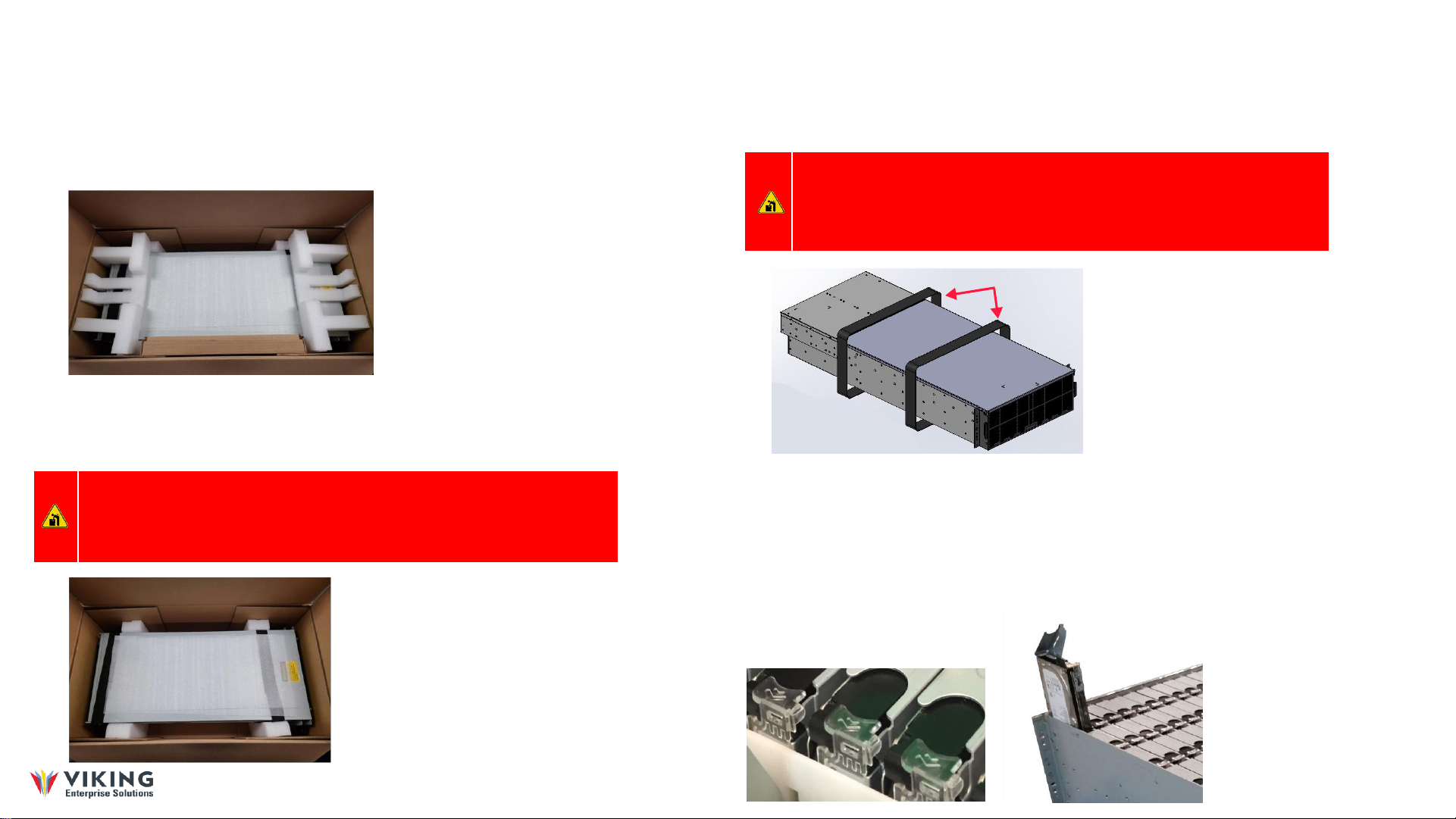
Figure 1 shows the contents of the shipping container when it is first opened.
Accessory Kit box
Figure 1 Open shipping container contents
2. Open the top of the box and remove the smaller box that contains the Accessory Kit. Inspect the
Accessory Kit box for shipping damage.
3. Remove the foam tray from the carton and inspect the enclosure for shipping damage. Figure 3.2 on
page 31 shows the enclosure ready to be removed from the packaging.
HEAVY OBJECT: This system weighs approximately 116.1 kilograms (256.0 pounds) when all 102 drives,
two PSUs, and two IOMs are preinstalled at the factory. (This weight does not include the container
weight.) A fully loaded system weighs 124.7 kilograms (275.0 pounds) with the rails and CMA installed.
Prevent personal injury and equipment damage. Obtain assistance during rack installation and when
sliding the system in or out of the rack.
4. Remove the protective foam sheet and lift the enclosure from the packaging using the lift straps
shown in Figure 1.3. Use of a forklift or lift table is recommended. Always obtain assistance lifting
the enclosure from the container.
Accessory
Box
Figure 1.2 Enclosure ready for removal
WARNING: The handles mounted on the front of the enclosure are designed only for the
purpose of extending the enclosure from the rack into the serviceable position. They will
not support the entire weight of the enclosure. Do not attempt to lift the enclosure by the
handles, They will break and damage to the enclosure and/or personal injury may occur.
Figure 1.3 Removing the enclosure
Lift straps
5. If installed, remove the enclosure’s components to minimize enclosure weight during rack installation.
Place all components on an anti-static surface until the enclosure is installed in the rack and
ready to have the components reinstalled.
Release catch
Enclosure
front
To remove a drive carrier assembly from the enclosure, follow these steps. (When removing a drive carrier, it is
not necessary to remove any drive carrier containing a drive blank, or to remove a drive from the carrier.)
Press the release catch (see Figure 3.6 on
page 35) on the drive carrier in the direction of
the imprinted arrows—pointing to the rear of
the enclosure—to release the handle into the
open position.
Carefully lift the drive carrier
assembly out of the slot as
demonstrated
ONYX Series Quick Installation Guide Document CTC-DOC-003006

Installing ONYX Series Expansion Enclosure Rail Kit
Each rail kit has two components: one left rail and one right rail. When properly installed, the rail kit’s chassis member
(bolted to the sides of the enclosure) slides inside the rail kit’s cabinet member (bolted to the rack).
The rail kit includes:
•One left adjustable rack mounting rail, engraved “L”.
•One right adjustable rack mounting rail, engraved “R”.
•Two mounting plates
•22 Phillips® M5 X 10 flat head screws
•12 ø5.1 washers
•Four M5 cage nuts
•Four M5 X 13 screws
Installing the Cabinet Members into the Rack
Install the cabinet members into the standard 19-inch (48.3-centimeter) rack as follows.
1. Adjust the length of the left cabinet member rail to match the depth of the rack.
NOTE: R (right) and L (left) are marked on the outside of the adjustable rack mounting rails
to indicate the appropriate placement.
2. Align the rail to the desired position on the front and rear left rack post.
3. Secure the left rear cabinet member rail to the rear left rack post by inserting the stag (prongs) into the post.
4. Secure it in place using four M5 X 10 screws and four M5 conical washers.
5. Place the mounting plate onto the left front rack post, aligning the top screw hole with the rail.
6. Verify the rail is level.
7. Insert one of the M5 cage nuts into the square rack hole immediately above the rail as shown in Figure 1.4.
Figure 1.4 Right front mounting plate and rail
8. Insert a second M5 cage nut into the square rack hole immediately below the rail, also shown in Figure 3.10.
9. Secure the mounting plate and left cabinet member rail onto the front left rack post using five of the M5 X 10
flat head screws. Figure 3.10 on page 39 demonstrates a properly installed right front mounting plate and rail.
10. Repeat steps 1 through 9 to secure the right cabinet member rail to the front and rear right rack posts.
Rail kit installation is complete. Install the enclosure into the rack.
INSTALLING THE ENCLOSURE INTO THE RACK
To install the VDS41022 JBOD Enclosure into the rack, follow these steps:
NOTE: The rail kit supports a 68.6-centimeter (27-inch) to 81.3-centimeter (32-inch) rack
depth. The enclosure depth is 92.7 centimeters (36.5 inches) without the CMA, and 100.0
centimeters (39.4 inches) with the CMA installed.
1. Fully extend the cabinet member rails.
HEAVY OBJECT: This system weighs approximately 116.1 kilograms (256.0 pounds) when all
102 drives, two PSUs, and two IOMs are preinstalled at the factory. (This weight does not
include the container weight.) A fully loaded system weighs 124.7 kilograms (275.0 pounds)
with the rails and CMA installed. Prevent personal injury and equipment damage. Obtain
assistance during rack installation and when sliding the system in or out of the rack.
WARNING: The handles mounted on the front of the enclosure are designed only for the
purpose of extending the enclosure from the rack into the serviceable position. They will not
support the entire weight of the enclosure. Do not attempt to lift the enclosure by the
handles, They will break and damage to the enclosure and/or personal injury may occur.
2. With a second person or lift table to assist in supporting the enclosure, align the inner chassis member rails
(attached to the enclosure) with the extended cabinet member rails.
3. Insert the inner chassis member rails into the extended cabinet member rails.
4. Push the enclosure into the rack until the rails lock in the serviceable position, indicated by an audible click.
5. With the enclosure installed in the serviceable position, reinstall the enclosure components.
ONYX Series Quick Installation Guide Document CTC-DOC-003006

Connecting the ONYX Series System
12
1
2
3
4
1. Connect the provided Mini-SAS HD cable to port 1 on both the 1U appliance and the 4U expansion enclosure as shown
in figure 1.5.
Figure 1.5 Power and Mini-SAS HD cables connectivity
2. Connect the provided power cables to both the 1U appliance and the expansion enclosure as shown in the red boxes.
3. Connect power cables from each power supply module to power sources.
4. Make sure to secure the power cables to the power supply modules so that they can not be pulled out accidentally.
5. Connect the Ethernet cables to the Ethernet ports as shown in the blue boxes
1. Power on any network switches, routers, or other standalone components.
2. Power on the expansion enclosure.
1. The storage enclosure does not contain a power button. Power is controlled by the two
power cords that plug into a power distribution unit (PDU). Fans, drives, IOMs, PSUs,
and 5V regulators are hot-swappable and do not require the system power to be shut
down during replacement.
3. Power on the ONYX Series chassis by pressing the power button on the front of the system.
ONYX Series Chassis
Power Cord Connectors
Expansion Enclosure
Power Cord Connectors
Power on the ONYX Series System Components
1. The default setting for the management IP address is DHCP. Check the DHCP server for the
ONYX Series leased IP address and you can go directly to the ONYX Series storage
management interface using a web browser e.g. http://192.168.1.x.
Discover the ONYX Series System
NOTE: The expansion enclosure required 200v-240v power source to have N+1 redundancy
You can access the ONYX Series storage management GUI using the below interfaces:
Ethernet Management port
Serial Port –Access the ONYX Series system directly from a computer using the provided RS-232C
serial cable
Note: If the LAN doesn’t have a DHCP server, the management port will be assigned a fix
IP address: 169.254.1.234/16. So you can configure the IP address of your management
computer to the same subnet domain of the storage system, e.g.: 169.254.1.1/16. Then
open a browser and enter http://169.254.1.234 to go into the login page.
1. Connect your computer to the ONYX Series system using the provided RS-232C
serial port cable
2. Launch a VT-100 terminal emulation application on your computer
3. Configure the serial port as (8-N-1-115200)
4. Login as admin/1234
5. Enter “info” to see the ONYX Series storage management IP address(es)
ONYX Series Quick Installation Guide Document CTC-DOC-003006
Other manuals for ONYX Series
1
Table of contents
Other Viking Enclosure manuals
Popular Enclosure manuals by other brands

Rosewill
Rosewill RX81US-HT35A-BLK user manual

SINGULARITY COMPUTERS
SINGULARITY COMPUTERS Eclipse Series Assembly manual

CommScope
CommScope FOSC-450A Installation instruction

ENERMAX
ENERMAX JAZZMATE manual

2B Technologies
2B Technologies 106 installation manual

ETC
ETC OneTrack Backbone T-coupler Housing installation guide