Viking W-3000 Instructions for use

P
Pr
ra
ac
ct
ti
ic
ce
e
T
TE
EL
LE
EC
CO
OM
MS
SO
OL
LU
UT
TI
IO
ON
NS
SF
FO
OR
RT
TH
HE
E2
21
1S
ST
TC
CE
EN
NT
TU
UR
RY
Y
TECHNICAL
TECHNICAL
Answer Your Door or Gate from any
Phone in Your Home or Business
Answer your door or gate from the safety of your telephone!
The W-3000 weather resistant, handsfree doorbox provides an
attractive and vandal resistant stainless steel faceplate. It is
designed to interface directly with the unused telephone line input
of nearly any phone system. One or two doorboxes can also share
an existing residential phone line when used with a C-1000B door-
box controller.
When the “Call“ button is pressed, the doorbox generates a stan-
dard or custom ring cadence of an adjustable number of rings. For
F
Fe
ea
at
tu
ur
re
es
s
P
Ph
ho
on
ne
e.
..
..
.7
71
15
5.
.3
38
86
6.
.8
88
86
61
1
Power: 120V AC/13.8V AC 1.25A UL listed adapter provided
Dimensions: Overall - 127mm x 127mm x 57.2mm (5.0” x 5.0”
x 2.25”) Plastic Rough-In Box - 102mm x 102mm x 54mm (4.0” x
4.0” x 2.12”)
Shipping Weight: 1.81 Kg (4 lbs)
Operating Temperature: -26°C to 54°C (-15°F to 130°F)
Humidity: W-3000 - 5% to 95% non-condensing humidity, W-
3000-EWP - Up to 100% condensing humidity
Ringer Output: 20 Hz, 3.0 REN load maximum
Maximum Loop Length: 1.9 Km (6300 ft) - 24 AWG twisted pair
Maximum Power Run: 38.1 m (125 ft) - 24 AWG twisted pair
Note: Power run length may be increased, see Wiring section
Connections: W-3000 - (4) position screw terminal strip, W-
3000-EWP - Gel filled butt connectors
S
Sp
pe
ec
ci
if
fi
ic
ca
at
ti
io
on
ns
s
noisy environments, the doorbox’s new louder speaker output and
“Push-to-Talk” feature can be used.
The W-3000-EWP shares all of the features of the W-3000 in addi-
tion to Enhanced Weather Protection (EWP) for installation in
harsh environments. EWP products feature rubber gaskets and
boots, hand soldered silicon sealed connections, gel filled butt
connectors, urethane potted circuit boards with weather sealed,
field adjustable trim pots and DIP switches for easy on-site pro-
gramming.
W
W-3000/
-3000/
W
W-3000-EWP
-3000-EWP
Vandal Resistant
Handsfree Doorbox
July 14, 2004
• Vandal resistant, 14 gauge stainless steel faceplate,
heavy-duty metal push button and mounting gasket.
Flush mount using the included rough-in box or
surface mount using an optional VE-5x5 backbox
• Yellow call progress/
night light LED
• New high output speaker amplifier with volume
adjustment POT
• Microphone volume adjustment POT
• 24 volt talk battery
• 20 Hz ring generator (3.0 REN ring load maximum)
• Selectable ring cadence (standard or 2 short rings)
• Selectable number of rings (2, 3, 10 or 30)
• Selectable “Push-to-Talk” feature for noisy
environments
• Extended operating temperature range: -15°F to 130°F
• Compact 45° terminal strip for easy wiring
• W-3000-EWP has Enhanced
Weather Protection
A
Ap
pp
pl
li
ic
ca
at
ti
io
on
ns
s
• Ideal for noisy locations in “Push-to-Talk” mode
• Commercial, industrial or residential door security
• Door or gate communication
• Truck stop/gas station fuel island communication
• Use with the C-1000B controller for single line residen-
tial systems or when the operation of door strikes or
gate openers is necessary
W-3000 shown with optional VE-5x5
?Need More Information on VE-5x5?
Call (715) 386-4345 and select 424.
?Need More Information on the C-1000B?
Call (715) 386-4345 and select 155.
h
ht
tt
tp
p:
:/
//
/w
ww
ww
w.
.v
vi
ik
ki
in
ng
ge
el
le
ec
ct
tr
ro
on
ni
ic
cs
s.
.c
co
om
m
?Need More Information on EWP?
Call (715) 386-4345 and select 859.

Front View of Optional
VE-5x5 (not included)
2.25”
Condensation
Drain Hole
*1/8" thick foam gasket (included)
5.14”
5.22” 3.25”
Call
4.0"
Rear View of VE-5x5 (not included)
Push to Call Button
Yellow Call Progress/Nightlight LED
(4) 6-32 X 3/4” stainless steel, flat head,
hexdrive, screws (included)
Condensation Drain Hole
5.0” Typical W-3000 shown with
Viking Model
VE-GNP
Gooseneck
Pedestal
(4) 0.38” diameter (for gooseneck mounting)
(4) 0.2 x 0.43 slots for double gang box
(2) 0.2 x 0.43 slots for single gang box
(1) .74" dia 3.0” 3.3”
3.0”
2.1”
Wall Stud
Front View of Plastic
Rough-In Box (included)
Wire knock out
(2) Standard flat head dry wall
(sheet rock) screws (not included)
I
In
ns
st
ta
al
ll
la
at
ti
io
on
n
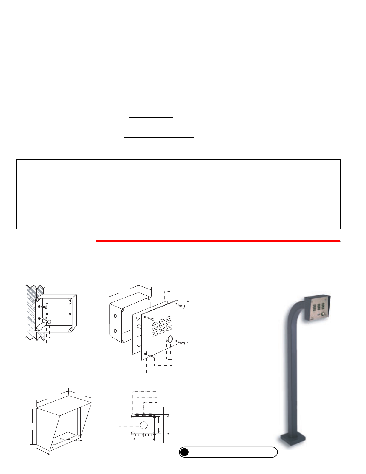
The optional VE-5x5 Surface Mount Box
is designed to be surface mounted to a
single gang box, double gang box or VE-
GNP gooseneck pedestal (right).
Important: The W-3000 will NOT mount to a
standard double gang box.
Caution: When warm air comes in contact with cold surfaces, such as outside walls, it causes condensation. To help prevent con-
densation from accumulating inside the W-3000, bring conduit into the bottom of the unit. If this is not possible, drill a 1/4” diameter
hole in the bottom of the plastic rough-in box.
Note: The plastic rough-in box (part # 259576)
may be purchased separately in advance. Go to
www.vikingelectronics.com and click on
“spare parts”.
?Need More Information on VE-5x5 or VE-GNP?
Call (715) 386-4345 and select 424.
* Note: Peel off paper liner and
adhere gasket to the back of the
faceplate, centering it over the four
corner mounting holes.
IF YOU HAVE A PROBLEM WITH A VIKING PRODUCT, PLEASE CONTACT: VIKING TECHNICAL SUPPORT AT (715) 386-8666
Our Technical Support Department is available for assistance Monday 8am - 4pm, Tuesday-Friday 8am - 5pm central time. So that we can give you better service, before you call please:
1. Know the model number, the serial number and what software version you have (see serial label).
2. Have your Technical Practice in front of you.
3. It is best if you are on site.
WARRANTY
Viking warrants its products to be free from defects in the workmanship or materials, under normal use and service, for a period of one year from the date of purchase from any authorized Viking distributor
or 18 months from the date manufactured, which ever is greater. If at any time during the warranty period, the product is deemed defective or malfunctions, return the product to Viking Electronics, Inc., 1531
Industrial Street, Hudson, WI., 54016. Customer must contact Viking's Technical Support Department at 715-386-8666 to obtain a ReturnAuthorization (R.A.) number.
This warranty does not cover any damage to the product due to lightning, over voltage, under voltage, accident, misuse, abuse, negligence or any damage caused by use of the product by the purchaser or
others.
Vikings sole responsibility shall be to repair or replace (at Viking's option) the material within the terms stated above. VIKING SHALLNOT BE LIABLE FORANY LOSS OR DAMAGE OFANY KIND INCLUD-
ING INCIDENTAL OR CONSEQUENTIAL DAMAGES RESULTING DIRECTLY OR INDIRECTLY FROM ANY BREACH OFANY WARRANTY EXPRESSED OR IMPLIED, OR FORANY OTHER FAILURE OF
THIS PRODUCT. Some states do not allow the exclusion or limitation of incidental or consequential damages, so this limitation may not apply to you.
THIS WARRANTY IS IN LIEU OF ALL OTHER WARRANTIES, EXPRESSED OR IMPLIED, INCLUDING THE WARRANTIES OF MERCHANTABILITY AND FITNESS FOR A PARTICULAR PURPOSE,
WHICH ARE HEREBY EXCLUDED BEYOND THE ONE YEAR DURATION OF THIS WARRANTY. Some states do not allow limitation on how long an implied warranty lasts, so the above limitation may not
apply to you.
RETURNING PRODUCT FOR EXCHANGE
The following procedure is for equipment that has failed out-of-box (within 10 days of purchase):
1. Customer must contact Viking’sTechnical Support at 715-386-8666 to determine possible causes for the problem. The customer MUST be able to step through recommended tests for diagnosis.
2. If the Technical Support Product Specialist determines that the equipment is defective based on the customer's input and troubleshooting, a Return Authorization (R.A.) number will be issued. This number is valid
for fourteen (14) calendar days from the date of issue.
3. After obtaining the R.A. number, return the approved equipment to your distributor, referencing the R.A. number. Your distributor will then replace the product over the counter at no charge. The distributor will
then return the product to Viking using the same R.A. number.
4. The distributor will NOT exchange this product without first obtaining the R.A. number from you. If you haven't followed the steps listed in 1, 2 and 3, be aware that you will have to pay a
restocking charge.
RETURNING PRODUCT FOR REPAIR
The following procedure is for equipment that needs repair:
1. Customer must contact Viking's Technical Support Department at 715-386-8666 to obtain a ReturnAuthorization (RA) number. The customer MUST have a complete description of the problem, with all pertinent
information regarding the defect, such as options set, conditions, symptoms, methods to duplicate problem, frequency of failure, etc.
2. Packing: Return equipment in original box or in proper packing so that damage will not occur while in transit. Static sensitive equipment such as a circuit board should be in an anti-static bag, sandwiched between
foam and individually boxed.All equipment should be wrapped to avoid packing material lodging in or sticking to the equipment. Include ALLparts of the equipment. C.O.D. or freight collect shipments cannot be
accepted. Ship cartons prepaid to: Viking Electronics, 1531 Industrial Street, Hudson, WI 54016
3. Return shipping address: Be sure to include your return shipping address inside the box. We cannot ship to a PO Box.
4. RAnumber on carton: In large printing, write the R.A. number on the outside of each carton being returned.
A. Mounting

DOOR ENTRY / CCTV VIDEO
/ PAGING CONTROLLER
VIKING©MODEL C-1000B
PWR13.8 VAC
DOOR
STRIKE1
DOOR
STRIKE2
DOORBOX2
DOORBOX
PWROUTPUT
DOORBOX1
123456789
10 11 12 13 14 15 16 17 18 19
EARTH
GND
PHONE LINE
INPUT
LINE OUT
TO PHONES
KEYLESS CONTACT
CLOSURE INPUT
VIKING
ELECTRONICS
HUDSON, WI 54016
EARTH
GND
C.O. LINE
INPUT
OUT TO
PHONES
KEYLESS
C.C. INPUT
DOOR
BOX 1
DOORBOX
13VAC PWR
DOOR
BOX 2
N.O. COM N.C.
DOOR STRIKE 1
SIG GND
VIDEO 1 IN
SIG GND
VIDEO 2 IN
SIG GND
VIDEO OUT
N.O. COM N.C.
DOOR STRIKE 2
TALK BATTERY
OFF ON
C
LED1
C
LED2
C
LED3
ON
1 2 3
COM N.O. N.C. - - - - AUX.
CONTACT
OUTPUT
or
Unused
PABX/KSU
Trunk Input
3.63" Typical
3.63"
*** 13.8VAC
(18VAC max)
120V AC
* Gel-filled butt
connectors
(EWP only)
Gel-filled butt
connectors
(EWP only)
Red
Green
T&R 13V
OUT AC
14
3
2
ON
** Earth
Ground
(optional)
(Spade connector
included)
Multi-Line
Phone
C.O.
Line
C-1000B Controller
Single Line
Phone
IMPORTANT: Electronic devices are susceptible to lightning and power station elec-
trical surges from both the AC outlet and the telephone line. It is recommended that
a surge protector be installed to protect against such surges. Contact Panamax at (800)
472-5555 or Electronic Specialists Inc. at (800) 225-4876.
!
Important: Do NOT install a W-3000 on a telephone line
without a C-1000B Controller (Fax Back Document 155).
Sw 1
OFF
ON
Ring Cadence
Standard: (1 second ON, 3 seconds OFF)
Custom (2 short rings): 0.5 seconds ON, 0.25 seconds OFF,
0.5 seconds ON, 3 seconds OFF
B. Wiring
P
Pr
ro
og
gr
ra
am
mm
mi
in
ng
g
D. Microphone and Speaker Volume Adjustment POTs
In certain noisy locations, the microphone volume may need to be
decreased. A microphone POT (see right) is provided on the W-
3000’s circuit board to increase or decrease the microphone vol-
ume. However, in extremely noisy locations the microphone POT
adjustment may not be enough to allow two-way talk path. In this
case the “Push-to-Talk” mode should be used as shown above
(see section Cabove).
Note: Both POTs come factory set in the middle position. A
speaker volume POT is also provided for increasing or decreas-
ing the speaker audio as needed.
B. Handsfree Operation (Dip Switch 4 - OFF)
When the “Call” button is pressed, the call progress LED will turn off and the W-3000 will begin generating a 20 Hz ring
signal. The caller at the W-3000 will hear an audio ring back signal while the LED flashes. When the inside party has
answered, the LED will light until the inside party hangs up. At that point, the LED will turn off for approximately one
second and then light steady to illuminate the W-3000 after dark.
C. Push-To-Talk Operation (Dip Switch4-ON)
In extremely noisy locations, the “Push-to-Talk” mode should be used. To switch to the “Push-to-Talk” mode, place DIP
switch 4 in the ON position (see Dip Switch Programming). To initiate a call, momentarily press the “Call” button to
generate the ring signal. After the inside party has answered, press and hold the call button to talk. Release the call
button to listen.
A. DIP Switches
1 2 3 4
ON
DIP
Switches
T&R 13V
OUT AC
14
3
2
ON
Sw 3
OFF
OFF
ON
ON
Ring Output
2 Ring
3 Rings
10 Rings
30 Rings
Sw 2
OFF
ON
OFF
ON
Communication Mode
Normal Handsfree Mode
Push-to-Talk Mode
Sw 4
OFF
ON
T&R 13V
OUT AC
14
3
2
ON
Min Max
Min Max
Speaker
Microphone
** Note: To increase surge protection, loosen the PCB mounting screw labeled (as shown above) and fasten a wire with spade terminal (includ-
ed) from the mounting screw to Earth Ground (grounding rod, water pipe, etc.)
* Note: The gel-filled (water-tight) butt connectors are designed for insulation displacement on 19-26 guage wire with a maximum insulation of 0.082
inches. Do not strip wires prior to terminating.
*** Warning: The power run wire length is limited to 125 ft of 24 AWG wire. Longer power runs will require heavier gauge wire (doubling pairs)
and/or a higher voltage power adapter. Power runs from 125 - 250 ft of 24 AWG wire are possible using a Radio Shack 18VAC adapter (part # 273-
1690). Voltage at the doorbox power input connections must not exceed 18VAC RMS.

Due to the dynamic nature of the product design, the information contained in this document is subject to change without notice. Viking Electronics, and its affiliates and/or
subsidiaries assume no responsibility for errors and omissions contained in this information. Revisions of this document or new editions of it may be issued to incorporate
such changes.
Fax Back Doc 180
ZF301750 Rev C
Printed in the U.S.A.
P
Pr
ro
od
du
uc
ct
tS
Su
up
pp
po
or
rt
tL
Li
in
ne
e.
..
..
.7
71
15
5.
.3
38
86
6.
.8
86
66
66
6F
Fa
ax
xB
Ba
ac
ck
kL
Li
in
ne
e.
..
..
.7
71
15
5.
.3
38
86
6.
.4
43
34
45
5
O
Op
pe
er
ra
at
ti
io
on
n
C-1000B Door Entry Controller
The C-1000B allows single line phones or phone systems to share a phone line
with one or two doorboxes or paging amplifiers. The C-1000B provides two Touch
Tone controlled relays to operate door strikes or gate openers and provides
doorbox triggered CCTV camera switching. Doorboxes and paging amplifiers
can now be used on single line, residential or home office applications as well as
on fully loaded systems, because they are no longer limited to installation on
unused trunk ports. The C-1000B expands the potential installation sites for many
peripherals such as doorboxes and paging amplifiers.
O
Ot
th
he
er
rR
Re
el
la
at
te
ed
dP
Pr
ro
od
du
uc
ct
ts
s
RC-2A Remote Touch Tone Controller
The RC-2A Remote Controller provides remote relay operation from any
standard Touch Tone telephone.
The controller is designed to be installed either locally or remotely. For local
installations the RC-2A can be installed in series on any analog communica-
tions path, such as analog C.O. lines, analog PABX/KSU stations or Viking’s
W-Series Doorboxes. and will passively monitor for Touch Tone commands.
For off-premise applications, the RC-2A will answer analog C.O. lines or
PABX/KSU stations after a selectable ring delay. A field programmable access
code can also be programmed to prevent unauthorized usage. The RC-2A
will then allow remote relay operation.
LDB-3 Advanced Ring/Loop Detector
The LDB-3 Advanced Loop Detector monitors an analog phone line for ringing and/or an
off hook condition. A built-in relay can be activated when either of these conditions are
detected. This is ideal for monitoring line status or for providing a visual indication of such.
The LDB-3 can be used with any W-Series doorbox to provide a dry contact closure when
the button is pressed on the doorbox and can be maintained while communicating with the
doorbox if desired. This contact closure can be used to trigger a security camera or acti-
vate a doorbell system.
The LDB-3 comes complete with a 12 VDC power adapter, and can also provide switched
12VDC .35 Amp output to power external lights, etc. during ringing and/or off-hook condi-
tions.
In the idle state, the W-3000 provides 24V DC talk battery. The LED remains lit for night time visibility.
When the “Call” button is pressed, the W-3000 generates a standard or custom (double) ring cadence
(adjustable from 2-30 rings). The LED will turn off and then begin flashing during ringing. When the call is
answered, ringing will stop and the LED will light steady. When the called party hangs up, the LED will turn off
momentarily and then remain lit for the idle state.
?Need More Information on the C-1000B?
Call (715) 386-4345 and select 155.
?Need More Information on the RC-2A?
Call (715) 386-4345 and select 160.
?Need More Information on the LDB-3?
Call (715) 386-4345 and select 409.
Other manuals for W-3000
1
This manual suits for next models
1
Table of contents
Other Viking Enclosure manuals
Popular Enclosure manuals by other brands

ABB
ABB ACS150 series installation instructions

Extron electronics
Extron electronics HSA 400 Series installation guide

HP
HP BladeSystem c3000 Technology brief

Antec
Antec NINE HUNDRED TWO V3 User's manual

PCB Piezotronics
PCB Piezotronics IMI SENSORS Y682A00 Installation and operating manual

Outland Technology
Outland Technology OTPS1KW-ASM-ROV-R1 user manual