Viking VE-9x12 Instructions for use

VE-9x12(R/Y/B)-2
- E-10A
- E-30
- E-30-PT
- E-35
- E-60
- E-1600-20A
- W-1000
- W-3000
VE-9x20(R/Y/B)
- K-1500-7
- K-1900-7
- K-1900-8
R = Red
Y = Yellow
B = Black
VE-9x12(R/Y/B)-1
- E-1600A
- E-1600-03B
- E-1600-30A
- E-1600-60A
- E-1600-45A
- E-20B
- K-1500P-W
- K-1900W-2
- W-2000A
Added Protection for Your Viking Emergency Phone,
Entry Phone, Doorbox or Other Telecom Device
Dimensions: See “Specifications,” page 2
Shipping Weight: VE-9x12 - 5.9 kg (13 lbs), VE-9x20 - 7.7 kg
(17 lbs)
Colors: Red with silver lettering, yellow with red lettering or
matte black with silver lettering
Conduit Opening: ½” NPT top and bottom with top plug
P
Pr
ra
ac
ct
ti
ic
ce
e
T
TE
EL
LE
EC
CO
OM
MS
SO
OL
LU
UT
TI
IO
ON
NS
SF
FO
OR
RT
TH
HE
E2
21
1S
ST
TC
CE
EN
NT
TU
UR
RY
Y
TECHNICAL
TECHNICAL
S
Sp
pe
ec
ci
if
fi
ic
ca
at
ti
io
on
ns
s
h
ht
tt
tp
p:
:/
//
/w
ww
ww
w.
.v
vi
ik
ki
in
ng
ge
el
le
ec
ct
tr
ro
on
ni
ic
cs
s.
.c
co
om
m
P
Ph
ho
on
ne
e.
..
..
.7
71
15
5.
.3
38
86
6.
.8
88
86
61
1
i
in
nf
fo
o@
@v
vi
ik
ki
in
ng
ge
el
le
ec
ct
tr
ro
on
ni
ic
cs
s.
.c
co
om
m
A
Ap
pp
pl
li
ic
ca
at
ti
io
on
ns
s
F
Fe
ea
at
tu
ur
re
es
s
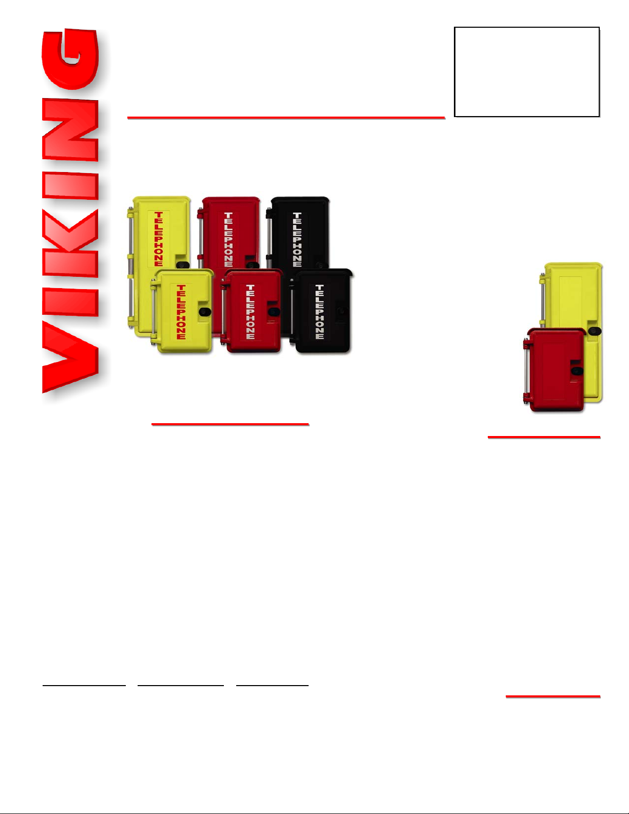
The VE-9x12 and VE-9x20 provide the ultimate in
weather protection for your Viking product or other
telecom devices.
These enclosures are constructed of cast aluminum
and are made for years of out-
door service. The heavy-duty alu-
minum doors are labeled
“Telephone” and have a gasket
seal to keep out even the harsh-
est weather. The VE-9x12 allows
you to choose from two panels
that allow mounting many differ-
ent Viking products.
Both the VE-9x12 and VE-9x20
are available in three high visibility colors: emergency red with silver lettering, safety
yellow with red lettering, or black with silver lettering.
• Heavy-duty 319 cast aluminum construction
• Powder coated for durability and UV stability
• Drip guard and gasket sealed door
• 0.020” thick stamped aluminum “Telephone” label with
scratch resistant UV stable clear coat
• ½” NPT conduit openings on top and bottom
• Available in Emergency Red, Safety Yellow or matte Black
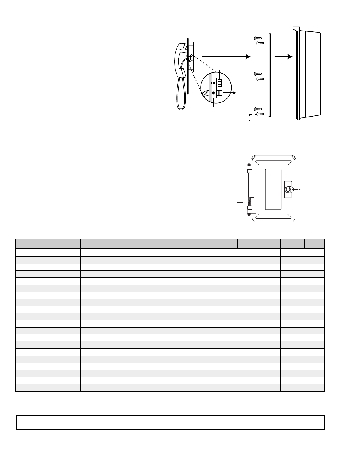
• Mounting holes for a standard RJ11 wall plate (VE-9x12
with adapter panel 1)
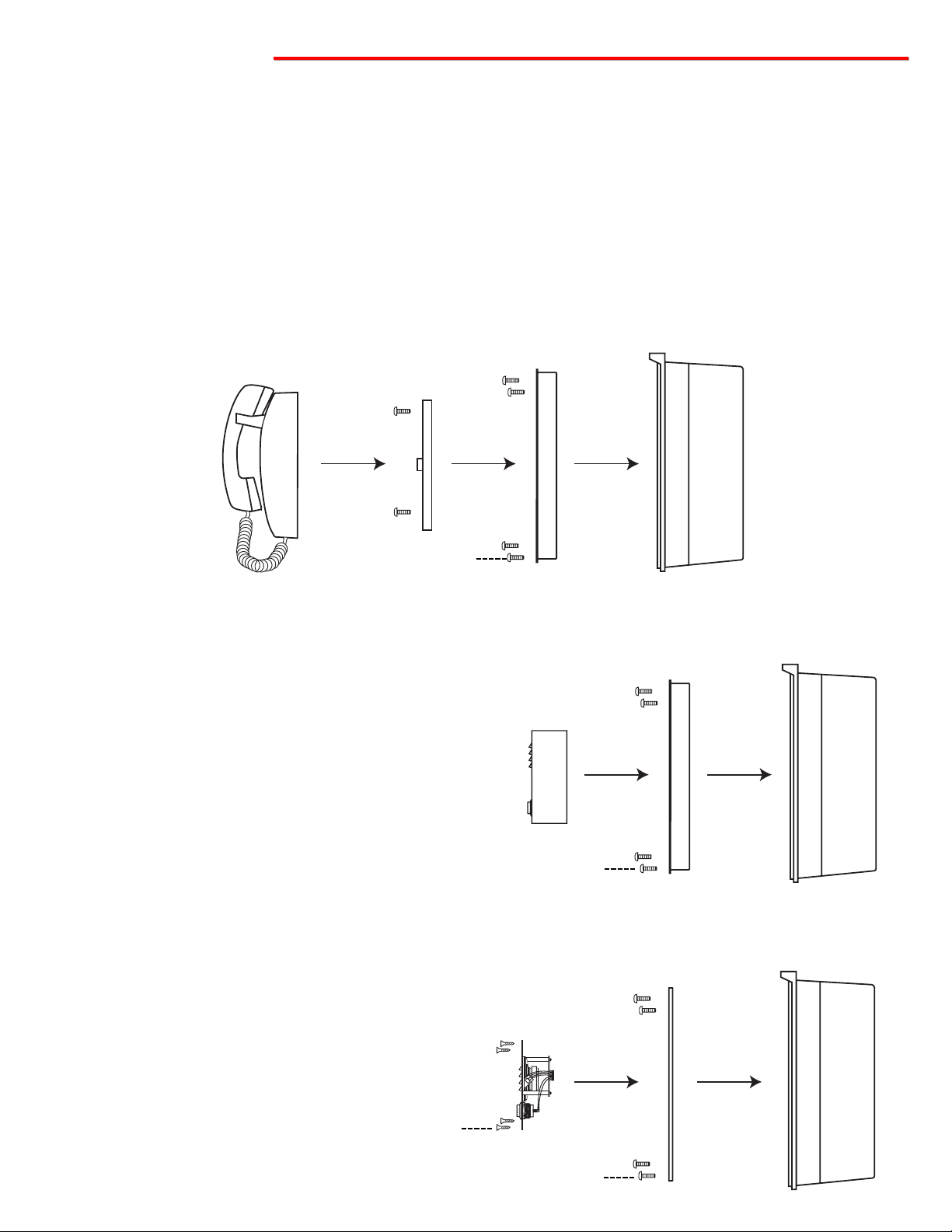
• VE-9x12 available with two adapter panels
• VE-9x20 comes with a standard adapter panel
• Hardware included with all adapter panels
• Optional VE-SPG door return hinge spring available
• Optional VE-PBL push button lock and key set available
• VE-9x12-0 and VE-9x20-0: Enclosures without adapter
plates for mounting other (non-Viking) telecom products,
available in all three colors, label included
• Compatible with these Viking products:
• Parking lots
• Maintenance areas
• Building exteriors
• Swimming pools
• Play grounds
• Roadside help areas
VE-9x12/VE-9x20
VE-9x12/VE-9x20
Outdoor
Enclosures
December 2, 2008
VE-9x20(B)VE-9x20(Y) VE-9x20(R)
VE-9x12(B)
VE-9x12(Y) VE-9x12(R)
VE-9x20(Y)-0
VE-9x12(R)-0

7.08 0.29
0.29
10.725 11.23
3.70
1.810
3.625
5.615
1.85
0.36 Typ.
3.25
3.625
3.54
3.70
1.81
0.36
1.85
0.25
(4) 6-32
Clinch Nuts
0.08
0.203 Dia.
4 Places
S
Sp
pe
ec
ci
if
fi
ic
ca
at
ti
io
on
ns
s
8.0
6.50
7.08
2.50
10.725
(4) 0.43 Dia.
Knockout
9.375
12.6
7.10
3.55
1.25
7.10
1.625
0.875
3.55
Center Line
Center Line
1/2" NPT
Plug
1/2" NPT
Conduit
Hole
E
E
E
P
H
N
O
T
L
5.92
11.23
(4) Tapped
8-32x0.5
2.704.0
7.45
Adapter Panel
Location
7.08
5.48
11.23
3.30
2.50
4.40
1.65
1.25
1.25
2.74
2.50 1.25
0.80
Typ.
(2) 8-32
Clinch Nuts
0.203 Dia.
4 Places
A. VE-9x12 Box
Inside
Base View
Side View Front View
1. Adapter Panel 1 2. Adapter Panel 2
B. VE-9x12 Adapter Panels
9.25
20.25
7.25
2.70
Adapter Panel
Location
E
E
E
P
H
N
O
T
L
8.0
6.50
7.08
6.0
18.28
(4) 0.43 Dia.
Knockout
5.92
18.76
(6) Tapped
8-32x0.5
6.49
9.14
18.76
(4) Tapped 6-32
(6) 0.218 Diameter
7.02
18.28
9.50
9.00
4.50
4.60
4.0
7.02
3.51
0.75
7.02
1.75
0.75
3.51
Center Line
Center Line
1/2" NPT
Plug
1/2" NPT
Conduit
Hole
C. VE-9x20 Box
Rear View
Side View Front View Adapter Panel
Minimum Internal Clearance: 5.75” x 10.0” x 6.75”
(12 gauge Aluminum Black Powder Paint)
Minimum Internal Clearance: 5.75” x 10.0” x 5.25” (12 gauge Aluminum Black Powder Paint)
Minimum Internal Clearance: 5.75” x 10.0” x 4.0”
Minimum Internal Clearance: 5.75” x 17.25” x 6.75”
(14 gauge Stainless Steel)
Minimum Internal Clearance: 5.75” x 17.25” x 4.0”
Top View
Bottom View
Top View
Bottom View

I
In
ns
st
ta
al
ll
la
at
ti
io
on
n
K-1900W-2 or K-1500P-W
(not included) RJ-11 Wall Plate
(not included)
Adapter Panel #1
(included)
VE-9x12 Box
(included)
B. Using the VE-9x12 to mount the K-1900W-2 or K-1500P-W
1. Mount the VE-9x12 to the wall, or surface desired, using the (4) corner mounting holes.
2. Run the conduit and wiring as appropriate.
3. Attach adapter panel #1 using the (4) included 8-32 x 3/8 black cap screws.
4. Attach a standard RJ11 wall plate (Radio Shack part # 279-451 or equivalent).
5. Attach the K-1900W-2 or K-1500P-W to the RJ11 wall plate.
C. Using the VE-9x12 to mount the E-20B, E-1600A, E-1600-03B, E-1600-45A, E-1600-60A or W-2000A
1. Mount the VE-9x12 to the wall, or surface
desired, using the (4) corner mounting holes.
2. Run the conduit and wiring as appropriate.
3. Attach adapter panel #1 using the (4) includ-
ed 8-32 x 3/8 black cap screws.
4. Attach the Viking product directly to the
adapter using the installation instructions pro-
vided in the product’s Technical Practice.
E-1600A Shown
(not included)
Adapter Panel #1
(included)
VE-9x12 Box
(included)
D. Using the VE-9x12 to mount the E-10, E-30, E-60, E-1600-20A, W-1000 or W-3000
1. Mount the VE-9x12 to the wall, or surface
desired, using the (4) corner mounting holes.
2. Run the conduit and wiring as appropriate.
3. Attach adapter panel #2 using the (4) includ-
ed 8-32 x 3/8 black cap screws..
4. Attach the Viking product directly to the
adapter using the installation instructions
provided in the product’s Technical Practice.
W-3000 Shown
(not included)
Adapter Panel #2
(included)
VE-9x12 Box
(included)
(4) 8-32 x 3/8 black cap
screws (included)
(4) 8-32 x 3/8 black cap
screws (included)
(4) 8-32 x 3/8 black cap
screws (included)
(4) 6-32 flathead screws
(included with W-3000)
A. Adhering the Optional “Telephone” Label on the VE-9x12-0 or VE-9x20-0
1. Clean the recessed area on the door cover with isopropol alcohol.
2. Make sure the outside edges of the “Telephone” label are not warped upward (re-form if necessary). Remove
backing paper, then firmly press label in recessed area on the front cover.

Due to the dynamic nature of the product design, the information contained in this document is subject to change without notice. Viking Electronics, and its affiliates and/or subsidiaries
assume no responsibility for errors and omissions contained in this information. Revisions of this document or new editions of it may be issued to incorporate such changes.
Fax Back Doc 413 ZF301480 Rev DPrinted in the U.S.A.
P
Pr
ro
od
du
uc
ct
tS
Su
up
pp
po
or
rt
tL
Li
in
ne
e.
..
..
.7
71
15
5.
.3
38
86
6.
.8
86
66
66
6F
Fa
ax
xB
Ba
ac
ck
kL
Li
in
ne
e.
..
..
.7
71
15
5.
.3
38
86
6.
.4
43
34
45
5
Product
E-10A
E-20B
E-30
E-30-PT
E-35
E-60
E-1600A
E-1600-03B
E-1600-30A
E-1600-60A
E-1600-45A
K-1500P-W
K-1500-7
K-1900W-2
K-1900-7
K-1900-8
W-1000
W-2000A
W-3000
W-3005
Model Number
VE-9x12
VE-9x12
VE-9x12
VE-9x12
VE-9x12
VE-9x12
VE-9x12
VE-9x12
VE-9x12
VE-9x12
VE-9x12
VE-9x12
VE-9x20
VE-9x12
VE-9x20
VE-9x20
VE-9x12
VE-9x12
VE-9x12
VE-9x12
Color
R/Y/B
R/Y/B
R/Y/B
R/Y/B
R/Y/B
R/Y/B
R/Y/B
R/Y/B
R/Y/B
R/Y/B
R/Y/B
R/Y/B
R/Y/B
R/Y/B
R/Y/B
R/Y/B
R/Y/B
R/Y/B
R/Y/B
R/Y/B
Panel
2
1
2
2
2
2
1
1
2
1
1
1
1
2
1
2
2
DOD#
210
215
215
214
178
206
215
210
215
215
212
355
352
360
360
362
170
170
180
181
Description
Emergency speaker phone with call button, flush mount.
Emergency speaker phone with push button, surface mount.
Stainless steel handsfree phone with dialer, flush mount.
Stainless steel handsfree phone with dialer and push to talk button.
Stainless steel handsfree phone with color video camera.
Double gang entry phone with LED.
Red ADA compliant handsfree emergency phone.
Stainless steel ADA compliant handsfree emergency phone.
Stainless steel, flush mount ADA compliant handsfree emergency phone.
Blue ADA compliant handsfree emergency phone.
ADA compliant handsfree emergency phone, yellow.
Wall phone with ringer and network.
Vandal resistant stainless steel panel phone.
Hot-line wall phone with non-volatile memory.
Hot-line vandal resistant stainless steel panel phone.
Hot-line, stainless steel panel phone with keypad and armored cable.
Weather resistant handsfree doorbox, flush mount.
Weather resistant handsfree doorbox, surface mount.
Stainless steel handsfree doorbox, flush mount.
Stainless steel handsfree doorbox with color video camera.
2. Brass Collar - Loosen set
screw, using 3/32 hex key
(included)
1. 6-32 Nut-
Loosen
3. Pull cable to
desired length
(6) 8-32 x 3/8 stainless
steel cap screws (included)
Panel Phone
(not included)
Adapter Panel
(included)
VE-9x20 Box
(included)
E. Using the VE-9x20 to mount the K-1500-7, K-1900-7 or K-1900-8
1. Remove adapter panel from the VE-9x20 using
the included hex key.
2. Mount the VE-9x20 to the wall, or surface
desired, using the (4) corner mounting holes.
3. Run the conduit and wiring as appropriate.
4. Attach adapter panel.
5. Attach the Viking product directly to the adapter
panel using the installation instructions provid-
ed in the product’s Technical Practice.
Note: If you wish to shorten the armored cable of the panel
phones, you may do so by loosening the 6-32 nut and
brass collar located on the back of the stainless steel panel
and pulling the cable through to its desired length, then
retightening the nut and brass collar (see diagram right).
F. Optional VE-PBL Push Button Lock
Caution: When warm air comes in contact with cold surfaces, such as outside walls and conduits, it causes condensation. To pre-
vent condensation and moisture from accumulating inside the VE-9x12 or VE-9x20 always bring conduit into the bottom of the unit.
E
E
E
P
H
N
O
T
L
VE-PBL Push
Button Lock
VE-SPG Door
Return Spring
An optional VE-PBL lock and key set is available if you choose to keep your VE-Series
phone box locked. Please contact your distributor for pricing and availability.
Important: The lock and key set uses 9 different key combinations. If you wish to have
multiple VE-PBL’s keyed alike, a special order is required.
G. Optional VE-SPG Door Return Hinge Spring
An optional VE-SPG door return hinge spring is available to assure the door
is closed after use. Please contact your distributor for pricing and availability.
H. Compatible Products and Adapter Panels
This manual suits for next models
1
Other Viking Enclosure manuals