IMPORTANT: Electronic devices are
susceptible to lightning and power
station electrical surges from both the
AC outlet and the telephone line. It is recom-
mended that a surge protector be installed to
protect against such surges. Contact Panamax
at (800) 472-5555 or Electronic Specialists Inc.
at (800) 225-4876.
IF YOU HAVE A PROBLEM WITH A VIKING PRODUCT, PLEASE CONTACT: VIKING TECHNICAL SUPPORT AT (715) 386-8666
Our Technical Support Department is available for assistance Monday 8am-4pm and Tuesday-Friday 8am - 5pm central time. So that we can give you better service, before you call please:
1. Know the model number, the serial number and what software version you have (see serial label).
2. Have your Technical Practice in front of you.
3. It is best if you are on site.
WARRANTY
Viking warrants its products to be free from defects in the workmanship or materials, under normal use and service, for a period of one year from the date of purchase from any authorized Viking distributor or 18 months from the date manu-
factured, which ever is greater. If at any time during the warranty period, the product is deemed defective or malfunctions, return the product to Viking Electronics, Inc., 1531 Industrial Street, Hudson, WI., 54016. Customer must contact Viking's
Technical Support Department at 715-386-8666 to obtain a Return Authorization (R.A.) number.
This warranty does not cover any damage to the product due to lightning, over voltage, under voltage, accident, misuse, abuse, negligence or any damage caused by use of the product by the purchaser or others.
Vikings sole responsibility shall be to repair or replace (at Viking's option) the material within the terms stated above. VIKING SHALL NOT BE LIABLE FOR ANY LOSS OR DAMAGE OF ANY KIND INCLUDING INCIDENTAL OR CONSE-
QUENTIAL DAMAGES RESULTING DIRECTLY OR INDIRECTLY FROM ANY BREACH OF ANY WARRANTY EXPRESSED OR IMPLIED, OR FOR ANY OTHER FAILURE OF THIS PRODUCT. Some states do not allow the exclusion or limi-
tation of incidental or consequential damages, so this limitation may not apply to you.
THIS WARRANTY IS IN LIEU OF ALL OTHER WARRANTIES, EXPRESSED OR IMPLIED, INCLUDING THE WARRANTIES OF MERCHANTABILITY AND FITNESS FOR A PARTICULAR PURPOSE, WHICH ARE HEREBY EXCLUDED
BEYOND THE ONE YEAR DURATION OF THIS WARRANTY. Some states do not allow limitation on how long an implied warranty lasts, so the above limitation may not apply to you.
RETURNING PRODUCT FOR EXCHANGE
The following procedure is for equipment that has failed out-of-box (within 10 days of purchase):
1. Customer must contact Viking’s Technical Support at 715-386-8666 to determine possible causes for the problem. The
customer MUST be able to step through recommended tests for diagnosis.
2. If the Technical Support Product Specialist determines that the equipment is defective based on the customer's input
and troubleshooting, a Return Authorization (R.A.) number will be issued. This number is valid for fourteen (14)
calendar days from the date of issue.
3. After obtaining the R.A. number, return the approved equipment to your distributor, referencing the R.A. number. Your
distributor will then replace the product over the counter at no charge. The distributor will then return the product to
Viking using the same R.A. number.
4. The distributor will NOT exchange this product without first obtaining the R.A. number from you. If you haven't
followed the steps listed in 1, 2 and 3, be aware that you will have to pay a restocking charge.
RETURNING PRODUCT FOR REPAIR
The following procedure is for equipment that needs repair:
1. Customer must contact Viking's Technical Support Department at 715-386-8666 to obtain a Return Authorization (RA)
number. The customer MUST have a complete description of the problem, with all pertinent information regarding the
defect, such as options set, conditions, symptoms, methods to duplicate problem, frequency of failure, etc.
2. Packing: Return equipment in original box or in proper packing so that damage will not occur while in transit. Static
sensitive equipment such as a circuit board should be in an anti-static bag, sandwiched between foam and individual-
ly boxed. All equipment should be wrapped to avoid packing material lodging in or sticking to the equipment. Include
ALL parts of the equipment. C.O.D. or freight collect shipments cannot be accepted. Ship cartons prepaid to:
Viking Electronics, 1531 Industrial Street, Hudson, WI 54016
3. Return shipping address: Be sure to include your return shipping address inside the box. We cannot ship to a PO Box.
4. RA number on carton: In large printing, write the R.A. number on the outside of each carton being returned.
I
In
ns
st
ta
al
ll
la
at
ti
io
on
n
Due to the dynamic nature of the product design, the information contained in this document is subject to change without notice. Viking Electronics, and its affiliates and/or
subsidiaries assume no responsibility for errors and omissions contained in this information. Revisions of this document or new editions of it may be issued to incorporate
such changes.
Fax Back Doc 428
ZF301930 Rev A
Printed in the U.S.A.
P
Pr
ro
od
du
uc
ct
tS
Su
up
pp
po
or
rt
tL
Li
in
ne
e.
..
..
.7
71
15
5.
.3
38
86
6.
.8
86
66
66
6F
Fa
ax
xB
Ba
ac
ck
kL
Li
in
ne
e.
..
..
.7
71
15
5.
.3
38
86
6.
.4
43
34
45
5
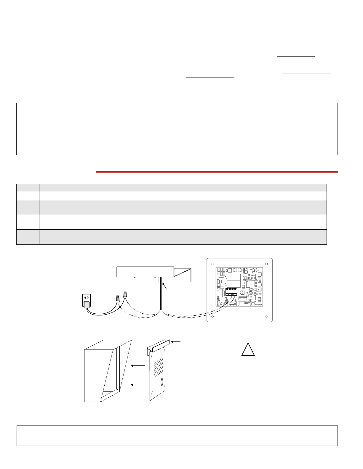
Step 1. Disconnect power from the doorbox or phone.
Step 2. Remove the doorbox or phone from the surface mount box (VE-5X5, VE-6X7, VE-5x10 or E-1600A-BLT-EWP).
Step 3. Connect the two wires from the VE-LIGHT to the power input terminals of the doorbox or use the included power
supply and wire nuts (see Diagram 1). Note: Wires can be connected in either polarity.
Step 4. Place the VE-LIGHT bracket against the upper mounting lip of the surface mount box and route wires through the
provided slot (see Diagram 1).
Step 5. Carefully place the phone or doorbox back into the surface mount box, making sure the wires stay in the slot
(see Diagram 2).


 user manual")


