manuals.online logo
Brands
  1. Home
  2. •
  3. Brands
  4. •
  5. Viking
  6. •
  7. Media Converter
  8. •
  9. Viking PF-6A Instructions for use

Viking PF-6A Instructions for use

PF-6A
PF-6A
Power Fail Bypass or
Ground to Loop
Start Converter
January 26, 2004
P
Ph
ho
on
ne
e.
..
..
.7
71
15
5.
.3
38
86
6.
.8
88
86
61
1
Power: 120 V AC/13.8V AC 1.25A, UL listed adapter provided or
24-48V DC, 100mA
Dimensions: 211mm x 160mm x 46mm (8.3” x 6.5” x 1.8”)
Shipping Weight: 1.2 kg (2.6 lbs)
Environmental: 0°C to 32°C (32°F to 90°F) with 5% to 95%
non-condensing humidity
Connections: (1) RJ21X, (1) RJ11
Power Failure Bypass System
P
Pr
ra
ac
ct
ti
ic
ce
e
T
TE
EL
LE
EC
CO
OM
MS
SO
OL
LU
UT
TI
IO
ON
NS
SF
FO
OR
RT
TH
HE
E2
21
1S
ST
TC
CE
EN
NT
TU
UR
RY
Y
TECHNICAL
TECHNICAL
S
Sp
pe
ec
ci
if
fi
ic
ca
at
ti
io
on
ns
s
F
Fe
ea
at
tu
ur
re
es
s
• Transfers six C.O. trunks directly to the
designated analog station phones
• Stackable to increase capacity
• Allows user to receive calls, as well as make
calls during power or system failure
• Compatible with loop start lines or 48V ground
start lines
• Automatic ground start converter eliminates
“ground start buttons”
• Power restoration will not interrupt calls in
progress
• Operates on power failure or normally open -
normally closed alarm contacts
The PF-6A power failure bypass system makes it
possible to receive calls during phone system and
power outages. The PF-6A bypass unit connects
6 pre-assigned single line station phones directly
to user-assigned C.O. trunks. A built-in ground
start converter permits outbound calls from stan-
dard phones.
When the system is restored, calls in progress are
not lost. The PF-6A bypass unit will reconnect
phones to their station circuits after they become
idle.
The PF-6A can be configured to operate when power is lost or from an opening/closing
of an alarm contact or manual closure.
Alternatively, the PF-6A can be used to convert six incoming ground start lines to loop
start lines. This accommodates installation of telephony equipment requiring loop start
lines (example: key systems, call sequencers, answering machines, voice mail, etc.)
h
ht
tt
tp
p:
:/
//
/w
ww
ww
w.
.v
vi
ik
ki
in
ng
ge
el
le
ec
ct
tr
ro
on
ni
ic
cs
s.
.c
co
om
m
i
in
nf
fo
o@
@v
vi
ik
ki
in
ng
ge
el
le
ec
ct
tr
ro
on
ni
ic
cs
s.
.c
co
om
m
• Prevents busy signals or unanswered calls
during power and system failures
• Converts ground start lines to standard loop
start lines
A
Ap
pp
pl
li
ic
ca
at
ti
io
on
ns
s
M
Ma
ad
de
ei
in
nt
th
he
eU
U.
.S
S.
.A
A.
.
I
In
ns
st
ta
al
ll
la
at
ti
io
on
n
POWER
VIKING©MODEL PF-6A
VIKING
ELECTRONICS
HUDSON, WI 54016
AUTOMATIC LINE
TRANSFER SWITCH
POWER
13.8VAC
13.8V AC
Adapter
Included
120V AC
ACTIVE
TEST
1 2 3
O
N
O
F
F
EXTERNAL
ALARM
EXTERNAL
ALARM
DIP SWITCH
1 2 3
TEST RJ21X
Power LED
Active LED
Test Button
DIP Switches
RJ21X Female
Connector
Normally Open Maintained Contact Input
IF YOU HAVE A PROBLEM WITH A VIKING PRODUCT, PLEASE CONTACT: VIKING TECHNICAL SUPPORT AT (715) 386-8666
Our Technical Support Department is available for assistance weekdays between 8 a.m. and 5 p.m. central time. So that we can give you better service, before you call please:
1. Know the model number, the serial number and what software version you have (see serial label).
2. Have your Technical Practice in front of you.
3. It is best if you are on site.
WARRANTY
Viking warrants its products to be free from defects in the workmanship or materials, under normal use and service, for a period of one year from the date of purchase from any authorized Viking distributor or 18 months from the date manu-
factured, which ever is greater. If at any time during the warranty period, the product is deemed defective or malfunctions, return the product to Viking Electronics, Inc., 1531 Industrial Street, Hudson, WI., 54016. Customer must contact Viking's
Technical Support Department at 715-386-8666 to obtain a Return Authorization (R.A.) number.
This warranty does not cover any damage to the product due to lightning, over voltage, under voltage, accident, misuse, abuse, negligence or any damage caused by use of the product by the purchaser or others.
Vikings sole responsibility shall be to repair or replace (at Viking's option) the material within the terms stated above. VIKING SHALL NOT BE LIABLE FOR ANY LOSS OR DAMAGE OFANY KIND INCLUDING INCIDENTAL OR CONSE-
QUENTIAL DAMAGES RESULTING DIRECTLYOR INDIRECTLYFROM ANY BREACH OFANY WARRANTYEXPRESSED OR IMPLIED, OR FOR ANY OTHER FAILURE OF THIS PRODUCT. Some states do not allow the exclusion or limi-
tation of incidental or consequential damages, so this limitation may not apply to you.
THIS WARRANTY IS IN LIEU OF ALLOTHER WARRANTIES, EXPRESSED OR IMPLIED, INCLUDING THE WARRANTIES OF MERCHANTABILITYAND FITNESS FOR APARTICULAR PURPOSE, WHICH ARE HEREBY EXCLUDED
BEYOND THE ONE YEAR DURATION OF THIS WARRANTY. Some states do not allow limitation on how long an implied warranty lasts, so the above limitation may not apply to you.
RETURNING PRODUCT FOR EXCHANGE
The following procedure is for equipment that has failed out-of-box (within 10 days of purchase):
1. Customer must contact Viking’sTechnical Support at 715-386-8666 to determine possible causes for the problem. The
customer MUST be able to step through recommended tests for diagnosis.
2. If the Technical Support Product Specialist determines that the equipment is defective based on the customer's input
and troubleshooting, a ReturnAuthorization (R.A.) number will be issued. This number is valid for fourteen (14)
calendar days from the date of issue.
3. After obtaining the R.A. number, return the approved equipment to your distributor, referencing the R.A. number. Your
distributor will then replace the product over the counter at no charge. The distributor will then return the product to
Viking using the same R.A. number.
4. The distributor will NOT exchange this product without first obtaining the R.A. number from you. If you haven't
followed the steps listed in 1, 2 and 3, be aware that you will have to pay a restocking charge.
RETURNING PRODUCT FOR REPAIR
The following procedure is for equipment that needs repair:
1. Customer must contact Viking's Technical Support Department at 715-386-8666 to obtain a Return Authorization (RA)
number. The customer MUST have a complete description of the problem, with all pertinent information regarding the
defect, such as options set, conditions, symptoms, methods to duplicate problem, frequency of failure, etc.
2. Packing: Return equipment in original box or in proper packing so that damage will not occur while in transit. Static
sensitive equipment such as a circuit board should be in an anti-static bag, sandwiched between foam and individual-
ly boxed.All equipment should be wrapped to avoid packing material lodging in or sticking to the equipment. Include
ALL parts of the equipment. C.O.D. or freight collect shipments cannot be accepted. Ship cartons prepaid to:
Viking Electronics, 1531 Industrial Street, Hudson, WI 54016
3. Return shipping address: Be sure to include your return shipping address inside the box. We cannot ship to a PO Box.
4. RAnumber on carton: In large printing, write the R.A. number on the outside of each carton being returned.
If the trouble is causing harm to the telephone network, the telephone company may request you to remove
the equipment from the network until the problem is resolved.
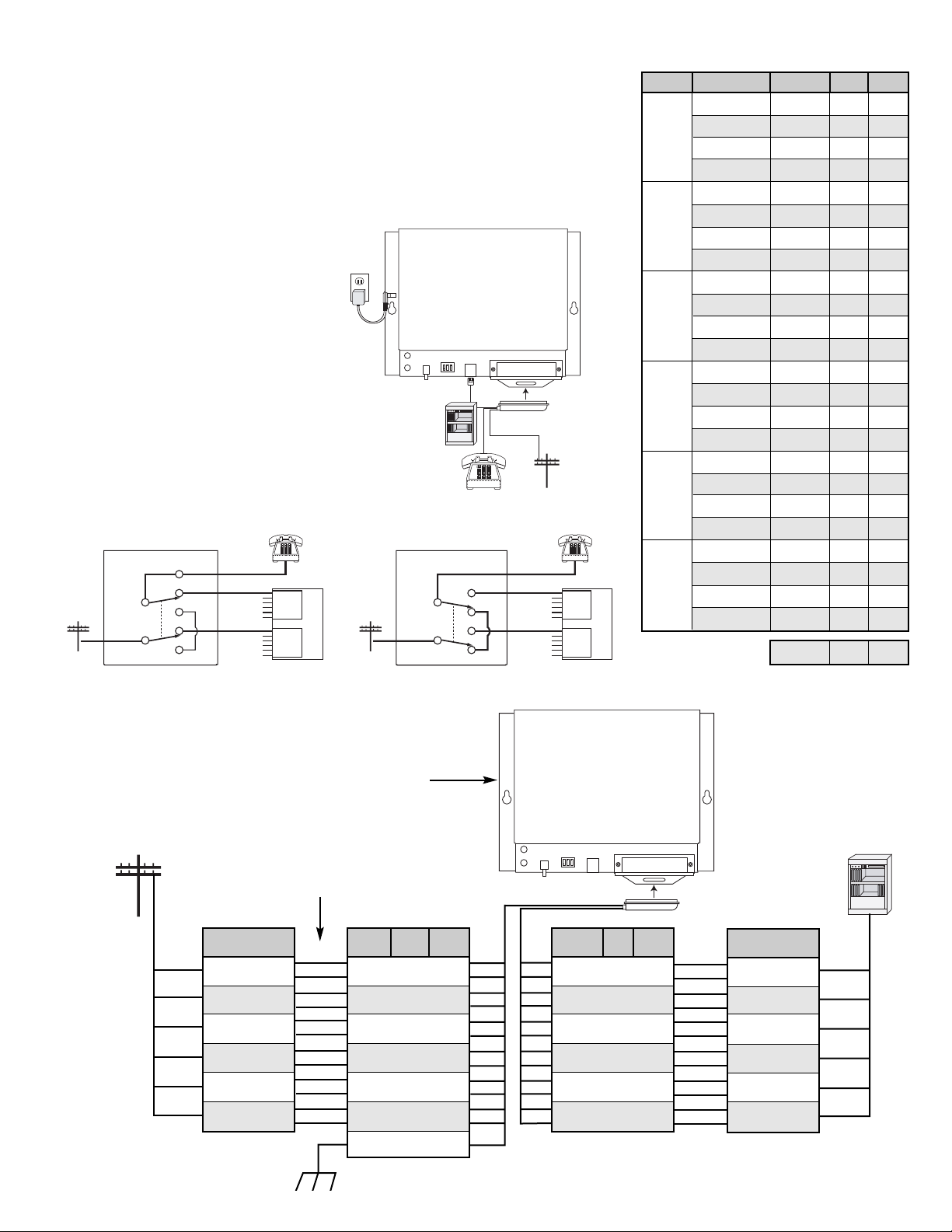
The PF-6Auses the USOC jack RJ21X.
It is recommended that the customer install anAC surge arrester in the AC outlet to which this device is con-
nected. This is to avoid damaging the equipment caused by local lightning strikes and other electrical surges.
This equipment is Hearing-Aid Compatible (HAC).
The telephone Consumer ProtectionAct of 1991 makes it unlawful for any person to use a computer or other
electronic device, including fax machines, to send any message unless such message clearly contains in a mar-
gin at the top or bottom of each transmitted page or on the first page of the transmission, the date and time it is
sent and an identification of the business or other entity, or other individual sending the message and the tele-
phone number of the sending machine or such business, other entity, or individual. (The telephone number pro-
vided may not be a 900 number or any other number for which charges exceed local or long-distance transmis-
sion charges.)
PART 15 LIMITATIONS
This equipment has been tested and found to comply with the limits for a ClassA digital device, pursuant to Part
15 of the FCC Rules. These limits are designed to provide reasonable protection against harmful interference
when the equipment is operated in a commercial environment. This equipment generates, uses, and can radi-
ate radio frequency energy and, if not installed and used in accordance with the instruction manual, may cause
harmful interference to radio communications. Operation of this equipment in a residential area is likely to cause
harmful interference in which case the user will be required to correct the interference at his own expense.
FCC REQUIREMENTS
This equipment complies with Part 68 of the FCC rules. Located on the equipment is a label that contains,
among other information, the FCC registration number and ringer equivalence number (REN). If requested, this
information must be provided to the telephone company.
The REN is used to determine the quantity of devices which may be connected to the telephone line.
Excessive REN's on the telephone line may result in the devices not ringing in response to an incoming call. In
most, but not all areas, the sum of the REN's should not exceed five (5.0) To be certain of the number of devices
that may be connected to the line, as determined by the total REN's, contact the telephone company to deter-
mine the maximum REN for the calling area.
This equipment cannot be used on the telephone company-provided coin service. Connection to Party Line
Service is subject to State Tariffs.
If this equipment causes harm to the telephone network, the telephone company will notify you in advance
that temporary discontinuance of service may be required. If advance notice isn't practical, the telephone com-
pany will notify the customer as soon as possible.Also, you will be advised of your right to file a complaint with
the FCC if you believe it is necessary.
The telephone company may make changes in its facilities, equipment, operations, or procedures that could
affect the operation of the equipment. If this happens, the telephone company will provide advance notice in
order for you to make the necessary modifications in order to maintain uninterrupted service.
If trouble is experienced with this equipment, please contact: Viking Electronics, Inc., 1531 Industrial
Street, Hudson, WI 54016 (715) 386-8666
The Power LED and Active LED
will be lit when the PF-6A is in the
normal operating mode. The
Active LED will go out and the
Power LED will stay lit when the
Test Button is pressed.
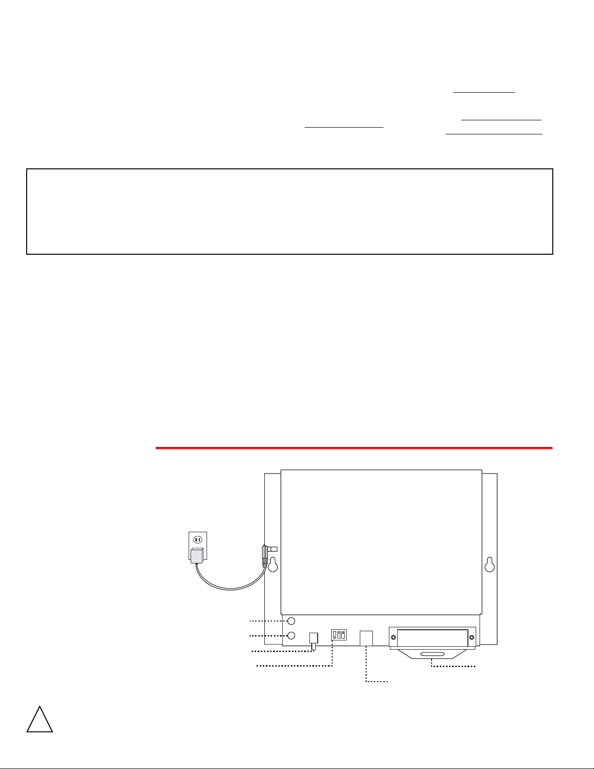
Note: The unit can also be powered by 24-48V
DC PABX battery supply on terminals 50 & 25.
IMPORTANT: Electronic devices are susceptible to lightning and power station electrical surges from both the AC outlet and the
telephone line. It is recommended that a surge protector be installed to protect against such surges. Contact Panamax at (800)
472-5555 or Electronic Specialists Inc. at (800) 225-4876.
!
C.O. Lines PABX/KSU
The first six C.O. lines should be interfaced with the PF-6A as shown in the chart to
the right. The PF-6A is sensitive to the polarity of the incoming telephone lines,
even when using loop start lines. There is a feature in the PF-6A that keeps a “power
fail” call from getting interrupted when power is restored (power restoration will not
interrupt calls in progress). With loop (or ground) start lines, if the C.O. dial tone
coming in is connected in the wrong polarity, this feature will not work. When wired
in reverse polarity and power is restored, a call in progress is dropped immediately.
If your system has an alarm contact or manual transfer switch, you must connect it
to the red and green wires of the
modular jack labeled EXTER-
NAL ALARM on PF-6A. This
must be a normally open main-
tained contact closure. If normal-
ly closed alarm contacts are
used, wire them to break the
power to the PF-6A when they
open.
Note: Loop start and ground
start CO lines may be combined
on the PF-6A (see
Programming). When ground
start lines are used, pin 50 (V/S)
must be connected to a good
earth ground.
A. Power Fail Bypass Unit
Circuit
Circuit 1
Circuit 2
Circuit 3
Circuit 4
Circuit 5
Circuit 6
Trunk/Station
Trunk 1 - IN
Trunk 1 - OUT
Station 1 - IN
Station 1 - OUT
Trunk 2 - IN
Trunk 2 - OUT
Station 2 - IN
Station 2 - OUT
Trunk 3 - IN
Trunk 3 - OUT
Station 3 - IN
Station 3 - OUT
Trunk 4 - IN
Trunk 4 - OUT
Station 4 - IN
Station 4 - OUT
Trunk 5 - IN
Trunk 5 - OUT
Station 5 - IN
Station 5 - OUT
Trunk 6 - IN
Trunk 6 - OUT
Station 6 - IN
Station 6 - OUT
Line
T1T-IN
T1R-IN
T1T-OUT
T1R-OUT
S1T-IN
S1R-IN
S1T-OUT
S1R-OUT
T2T-IN
T2R-IN
T2T-OUT
T2R-OUT
S2T-IN
S2R-IN
S2T-OUT
S2R-OUT
T3T-IN
T3R-IN
T3T-OUT
T3R-OUT
S3T-IN
S3R-IN
S3T-OUT
S3R-OUT
T4T-IN
T4R-IN
T4T-OUT
T4R-OUT
S4T-IN
S4R-IN
S4T-OUT
S4R-OUT
T5T-IN
T5R-IN
T5T-OUT
T5R-OUT
S5T-IN
S5R-IN
S5T-OUT
S5R-OUT
T6T-IN
T6R-IN
T6T-OUT
T6R-OUT
S6T-IN
S6R-IN
S6T-OUT
S6R-OUT
GND
-24/48V
Pins
26
1
27
2
28
3
29
4
30
5
31
6
32
7
33
8
34
9
35
10
36
11
37
12
38
13
39
14
40
15
41
16
42
17
43
18
44
19
45
20
46
21
47
22
48
23
49
24
50
25
Color
W/BL
BL/W
W/O
O/W
W/G
G/W
W/BN
BN/W
W/S
S/W
R/BL
BL/R
R/O
O/R
R/G
G/R
R/BN
BN/R
R/S
S/R
BK/BL
BL/BK
BK/O
O/BK
BK/G
G/BK
BK/BN
BN/BK
BK/S
S/BK
Y/BL
BL/Y
Y/O
O/Y
Y/GN
GN/Y
Y/BN
BN/Y
Y/S
S/Y
V/BL
BL/V
V/O
O/V
V/GN
GN/V
V/BN
BN/V
V/S
S/V
Station or Trunk
Control Line
Station
Output
Circuit
Trunk
Circuit
Input
C.O.
Lines
PABX
1
2
3
4
5
6
1
2
3
4
5
6
Station 1 OUT (W/BN)
Station 1
IN (W/G)
Trunk 1
OUT (W/O)
Trunk 1
IN (W/BL)
PF-6A in Normal Operating Mode
(typical for 6 lines)
Station
Output
Circuit
Trunk
Circuit
Input
C.O.
Lines
PABX
1
2
3
4
5
6
1
2
3
4
5
6
Station 1 OUT (W/BN)
Station 1
IN (W/G)
Trunk 1
OUT (W/O)
Trunk 1
IN (W/BL)
PF-6A in Bypass Mode
(typical for 6 lines)
POWER
VIKING©MODEL PF-6A
VIKING
ELECTRONICS
HUDSON, WI 54016
AUTOMATIC LINE
TRANSFER SWITCH
POWER
13.8VAC
Analog
PABX/KSU
Station
13.8V AC
Adapter
Included
120V AC
ACTIVE
TEST
1 2 3
O
N
O
F
F
EXTERNAL
ALARM
EXTERNAL
ALARM
DIP SWITCH
1 2 3
TEST RJ21X
RJ21X Male Jack
(not included)
C.O. Line
POWER
VIKING©MODEL PF-6A
VIKING
ELECTRONICS
HUDSON, WI 54016
AUTOMATIC LINE
TRANSFER SWITCH
POWER
13.8VAC
ACTIVE
TEST
1 2 3
O
N
O
F
F
EXTERNAL
ALARM
EXTERNAL
ALARM
DIP SWITCH
1 2 3
TEST RJ21X
RJ21X Male Jack
(not included)
The ground start converter in the PF-6A will only work properly when
connected in series with the ground start trunks as shown.
B. Ground to Loop Start Converter
Line
T1T-IN
T1R-IN
T2T-IN
T2R-IN
T3T-IN
T3R-IN
T4T-IN
T4R-IN
T5T-IN
T5R-IN
T6T-IN
T6R-IN
GND
Pins
26
1
30
5
34
9
38
13
42
17
46
21
50
Color
W/BL
BL/W
W/S
S/W
R/BN
BN/R
BK/G
G/BK
Y/O
O/Y
V/BL
BL/V
V/S
Tip
Ring
Tip
Ring
Tip
Ring
Tip
Ring
Tip
Ring
Tip
Ring
1
2
3
4
5
6
Incoming Ground
Start Trunks
+
-
+
-
+
-
+
-
+
-
+
-
Line
S1T-OUT
S1R-OUT
S2T-OUT
S2R-OUT
S3T-OUT
S3R-OUT
S4T-OUT
S4R-OUT
S5T-OUT
S5R-OUT
S6T-OUT
S6R-OUT
Pins
29
4
33
8
37
12
41
16
45
20
49
24
Color
W/BN
BN/W
R/G
G/R
BK/O
O/BK
Y/BL
BL/Y
Y/S
S/Y
V/BN
BN/V
Tip
Ring
Tip
Ring
Tip
Ring
Tip
Ring
Tip
Ring
Tip
Ring
1
2
3
4
5
6
Loop Start
Lines Out
Earth Ground (V/S) Important: Pin 50 MUST be connected to a good earth ground
for the PF-6A to function properly with ground start lines.
Important: Do NOT connect the
power adapter when using the PF-6A
in the Ground to Loop Start application.
The C.O. lines must be connected
in the correct polarity.
O
Op
pe
er
ra
at
ti
io
on
n
After installing and testing the PF-6A, instruct office personnel that in the event of the power failure or system failure that the six
assigned telephones will be the only means to receive and place calls.
While the PF-6A is in normal operating mode, the six C.O. lines are connected to the trunk inputs, and the six assigned station cir-
cuits are connected to their six telephones. In the event of either a power failure or a major PABX alarm, the PF-6A will shift into
the bypass mode. In this mode, the six C.O. trunks are instantly connected to the six analog telephones designated, bypassing the
PABX/KSU. Incoming calls will now ring directly to the telephones assigned to the six C.O. trunks. Outgoing calls may also be made
from each telephone, even on ground start lines.
When power is restored or the major alarm is cleared, the PF-6A will automatically switch back to normal operation. Any C.O. trunk
in use at this time will remain connected until the call is completed.
P
Pr
ro
og
gr
ra
am
mm
mi
in
ng
g
POWER
VIKING©MODEL PF-6A
VIKING
ELECTRONICS
HUDSON, WI 54016
AUTOMATIC LINE
TRANSFER SWITCH
POWER
13.8VAC
ACTIVE
TEST
1 2 3
O
N
O
F
F
EXTERNAL
ALARM
EXTERNAL
ALARM
DIP SWITCH
1 2 3
TEST RJ21X
1 2 3
ON
OFF
DIP
Switch
1
1
2
2
3
3
Position
OFF
ON
OFF
ON
OFF
ON
Description
Normal operation
Bypass mode for testing
Assigns lines 1, 2, 3 to loop start
Assigns lines 1, 2, 3 to ground start
Assigns lines 4, 5, 6 to loop start
Assigns lines 4, 5, 6 to ground start
A. Power Fail Bypass Unit
B. Ground to Loop Start Converter
The PF-6A can also be used as a ground start to loop start converter. This accommodates the installation of telephony equipment
requiring loop start lines (ie; key systems, call sequencers, answering machines, voice mail systems, etc.), to ground start C.O.
trunks. See Installation for proper wiring in this application.
In this application, the PF-6A will not pass disconnect supervision (“hang up” signals) to the loop start equipment. When a hang up
occurs, the PF-6A’s ground start converter automatically “restarts” the line and dial tone is returned to the loop start equipment. The
loop start equipment will not detect any disconnect, as this “restart” occurs immediately after the hang up. Typically this will cause
the loop start equipment to not release the telephone line when a caller abandons. Nothing can be done about this situation, as the
PF-6A can not distinguish the difference between this abandon condition and the loop start equipment going “off hook” to make an
outgoing call.
Note: The PF-6A can ONLY be used to convert ground start lines to loop start. It can NOT convert loop start lines to ground start.
After installation is complete, test the PF-6A by doing ONE of the following:
1. Press and hold the TEST button
2. Move DIP switch 1 to the ON position
3. Disconnect power to the PF-6A
4. Provide a maintained normally open contact closure to the EXTERNAL ALARM input
Due to the dynamic nature of the product design, the information contained in this document is subject to change without notice. Viking Electronics, and its affiliates and/or
subsidiaries assume no responsibility for errors and omissions contained in this information. Revisions of this document or new editions of it may be issued to incorporate
such changes.
Fax Back Doc 680
ZF301300 Rev B
Printed in the U.S.A.
P
Pr
ro
od
du
uc
ct
tS
Su
up
pp
po
or
rt
tL
Li
in
ne
e.
..
..
.7
71
15
5.
.3
38
86
6.
.8
86
66
66
6F
Fa
ax
xB
Ba
ac
ck
kL
Li
in
ne
e.
..
..
.7
71
15
5.
.3
38
86
6.
.4
43
34
45
5
C.O. Lines
PABX
Before System Outage
POWER
VIKING©MODEL PF-6A
VIKING
ELECTRONICS
HUDSON, WI 54016
AUTOMATIC LINE
TRANSFER SWITCH
POWER
13.8VAC
ACTIVE
TEST
1 2 3
O
N
O
F
F
EXTERNAL
ALARM
EXTERNAL
ALARM
DIP SWITCH
1 2 3
TEST RJ21X
C.O. Lines
PABX
PF-6A
After System Outage

Other Viking Media Converter manuals

Viking PF-6A Instructions for use

Viking

Viking PF-6A Instructions for use

Viking ACD-10 Instructions for use

Viking

Viking ACD-10 Instructions for use

Viking GLS-12 Instructions for use

Viking

Viking GLS-12 Instructions for use

Viking PF--6A Instructions for use

Viking

Viking PF--6A Instructions for use

Popular Media Converter manuals by other brands

Mitsubishi Electric FR-CC2-P instruction manual

Mitsubishi Electric

Mitsubishi Electric FR-CC2-P instruction manual

Axis Q7436 user manual

Axis

Axis Q7436 user manual

Alphacool Core quick start guide

Alphacool

Alphacool Core quick start guide

LUDLUM 2929 user manual

LUDLUM

LUDLUM 2929 user manual

Baumer Hubner Berlin POG 9 + FSL Mounting and operating instructions

Baumer

Baumer Hubner Berlin POG 9 + FSL Mounting and operating instructions

North Star Essentio operating manual

North Star

North Star Essentio operating manual

Kenwood DEM-999D instruction manual

Kenwood

Kenwood DEM-999D instruction manual

Rivera FS1-6M owner's manual

Rivera

Rivera FS1-6M owner's manual

Inovonics 510 Operating and maintenance instruction manual

Inovonics

Inovonics 510 Operating and maintenance instruction manual

Speaka Professional 1095853 operating instructions

Speaka Professional

Speaka Professional 1095853 operating instructions

KYLAND Technology KGW3102 Series Hardware installation manual

KYLAND Technology

KYLAND Technology KGW3102 Series Hardware installation manual

Kong CMP-SPLITDVI21 manual

Kong

Kong CMP-SPLITDVI21 manual

Pulsar DC/DC50HV manual

Pulsar

Pulsar DC/DC50HV manual

Ebyte ECAN-401 user manual

Ebyte

Ebyte ECAN-401 user manual

Siemens SIMOVERT 6SE7024-1EB85-0AA0 operating instructions

Siemens

Siemens SIMOVERT 6SE7024-1EB85-0AA0 operating instructions

SMC Networks 2102USB/ETH - FICHE TECHNIQUE Specifications

SMC Networks

SMC Networks 2102USB/ETH - FICHE TECHNIQUE Specifications

Caton NVP-903 Series reference guide

Caton

Caton NVP-903 Series reference guide

Philips SWS2103W Specifications

Philips

Philips SWS2103W Specifications

manuals.online logo
manuals.online logoBrands
  • About & Mission
  • Contact us
  • Privacy Policy
  • Terms and Conditions

Copyright 2025 Manuals.Online. All Rights Reserved.