Vikre Handel AS JIT-2040 User manual

CARPORT/SHELTER
MODEL: JIT-2040
L12.0xW6.2xH4.0M
www.vikre.no
Installation Manual

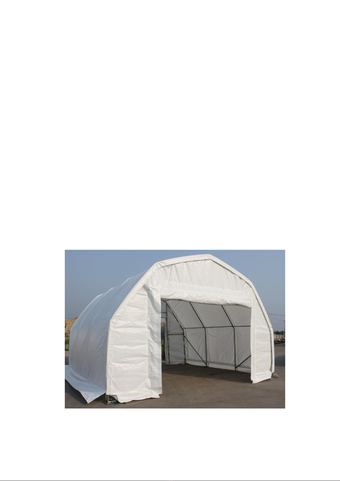
Congratulations on your purchase of our instant shelter. This unit is a combination of
excellent manufacturing and design. It is comprised of a rigid frame and a durable cover. For
easy assembly, we have marked all the parts with codes. With proper installation, use and
maintenance, your unit will provide many years of good and suitable service.
READALLTHE INSTRUCTIONS BEFOREASSEMBLY!
1. The proper erection and installation of this building requires a high level of care and safety.
We recommend the safety regulations be complied with during the installation. It includes
but is not limited to:
-Safety hats, protective eyewear and protective clothing
-Safety harnesses for all elevated workers
-Proper ladder, cage, and safety operation
2. Site selection: Choose a solid level location for your building. Do not install the building
where the ground could not keep the building steady. Do not install the building where the
ground could not bear the weight of the building. Do not install the building in soft grass
ground or wetland.
3. Be cautious with the surroundings. Keep work area clean. Do not set up it near snow drifts, in
slippery places, or in wet location. The cover of the building will protect against normal
falling leaves and light debris, however, large, fast or sharp falling items etc. may cause a
puncture or tear in the cover material. So, keep the building away from such harmful things.
Be careful with power and heat sources. Don’t keep heat sources near the tarpaulin. Don’t
expose to open flame.
4. Chose a windless day to install the building. It is very difficult to attach the cover in heavy
wind.
5. All snow accumulation on the main cover should be removed as soon as possible. Otherwise,
when old snow on the roof becomes hard with new snow falling in, it will increase the
burden of the roof badly and will damage the roof.
6. Try to keep the building, especially its base, in a dry condition. This will help the building to
have a longer life than keeping it in a wet condition.
7. The user should be responsible for the parts missing or damage occurred during the
installation.
8. Don’t make alteration of the frame. Don’t hang anything besides included parts to the frame.
Damages, consequential damages, or injuries caused by improper installation, alteration,
improper use, or damages caused by snow, wind, or any acts of nature are owing to the user.
The building is not intended for occupancy for any length of time.

ASSEMBLY PROCEDURE
1. Prepare location and place all unit boxes near location sight. Perform an inventory check
before beginning, to be certain all components are available for installtion.
2. Secure base plate flanges to base surface.
3. Assemble every group of arch.
4. Begin frame assembly with front end arch, first interior arch, purlins, etc.
5. Add to assemble other groups of arches.
6. Install main cover over frame.
7. Install end covers over end panels.
Read all the detailed instructions and notices in the following assembly instructions!
MAINTENANCE AND CARE
1. If some parts or the cover were accidently damaged during the use, contact the local supplier
for advises on the repairing method or replacements, so that to prevent from further damage
and keep the building in a good condition.
2. When replacing the parts, make certain the whole frame and the parts connected to the
replaced parts be well fixed or supported.
3. Same with when attaching the cover, choose a windless day to replace the cover. Begin with
making certain all the bolts of the frame and the tensioning equipments be well fixed. When
taking off the cover, make sure the related ropes, etc. be taken off, and the cover will not be
blocked during the way. Avoid taking off the cover with heavy big power equipments.
4. To enlongate the life of the cover, put small duct tape or foam rubber (provide it by yourself)
on the frame that comes to in contact with cover. The tape and foam rubber acts as a cushion
to avoid rubbing damage to the cover over years.
5. Periodically (once in half a year or more often), the building should be completely inspected
and maintained internally and externally to make certain the building remains properly
installed and secured. Including: check all bolts and hardware connectors to be certain they
are in place and tightened, the base plates are still fixed firmly, check and adjust the ropes if
in need, clean the cover with suitable washing. Allowing dirt and debris to sit on cover over
an extended time will damage cover irreparably.
Thanks again for choosing this quality product. The following is the detailed assembly
instructions for you starting the assembly.

Part Code Description Quantit
L Left roof tube 5
L1 Left roof tube in front panel 1
L2 Left roof tube in back panel 1
R Right roof tube 5
R1 Right roof tube in front panel 1
R2 Right roof tube in back panel 1
2 Shoulder tube 14
3 Sidewall tube 10
3A Sidewall tube at left of front panel 1
3B Sidewall tube in back panel 2
3C Sidewall tube at right of front panel 1
4 Horizontal tube 30
5L Base flange of left corners 2
5R Base flange of right corners 2
6L Base flange of left sidewall tube 5
6R Base flange of right sidewall tube 5
7Base flange of roll up door frame 2
7A Base flange of mechanical door frame 2
8Tie down ratchet for tensioning roof cover 14
9Upper standing tube of roll up door 2
10
Lower standing tube of roll up door
2
Part List of Model#JIT-2040
10
Lower standing tube of roll up door
2
11 Beam beside roll up door frame 2
12 Beam of the roll up door 2
14 Wind Brace Support 4
14A Tube clip for wind brace support 8
15 Pole for opening and closing the door 1
16 Stake peg 50
17 Lower roof cover tensioning tube 2sets
18 Tensioning tube (in the bottom) for front and back cover 4
19 M10x75 Bolt for "tapered" connection 110
20 M10x40 Carriage Bolt for horizontal tube 40
21 M10x30 Bolt for tube clip and connection plate 20
22 M10x85 Bolt for front and back panel and tube clip for horizontal tubes 54
22A M10x85 Carriage bolt for winch and beam 2
23 Plastic cap of tensioning tube 12
24 Roof cover 1
25 Back cover 1
25A Top cover above the mechanical door 1
25B Mechanical door cover 1
25C Front cover beside the door 2

26 Nylon bands for tensioning roof cover 14
27 Fastening rope for front&rear cover and the two ends of roof cover 135m
28 Upper door frame and track 2
29 Lower left door frame and track 1
29A Lower right door frame and track 1
30 Beam beside mechanical door frame 2
31 Beam for the winch of the door 1
32 Beam of the mechanical door 1set
33 Door dropping tube 6sets
33A Bottom door dropping tube 1set
34 Winch 1set
35 Tube clip for horizontal tube 35

L1
L
L2
R1
R
R2
2
3
3A
3C
3B
4
5R
5L
6R
6L
7
7A
9
10
11
12
14
18
28
29A
29
30
31
32
Figure 1 Sketch of JIT-2040
Size: L12*W6.2*H4M

Diagonals are equal
Locate the Left Corner Base Flange and
Right Corner Base Flange( 5R&5L).
Secure the base flanges with Stake Pegs
(Part #16). Measurements shown in
Figure 2 are to the center of the upright
sockets on each Base Flange.
The Shelter must be secured to a firm
surface that can receive and retain augers
and pegs firmly in position. The shelter
should be installed on FIRM GROUND,
not on SWAMP, SOFT/WET GROUND.
The Base Flanges must be secured so
they cannot be moved. Arches are
tensioned at their base as they insert into
the Base Plate sockets
Figure 2 Position of Base Flanges
Begin by determining exact location of
the four (4) corners of the building. Mark
front edge and side-to-side width of
assembly on ground. Drive alignment
stakes into the ground outside of the
markings, and draw alignment strings
along both ends and sides of the building
to the dimensions shown in Figure 3. The
outline of the strings will represent the
final location of the base flanges. The
initial location of each Corner Base
Flanges (5R & 5L) is critical to the
alignment and fit of the frame components
and cover.
Step #1 --SECURING BASE FLANGES
Sit the building boxes in the chosen location. Remove all the components
from packaging to ensure all components are present by checking with the
Part List.
Figure 3
As Figure 3 shows, each base
flange is equipped with two
stake pegs and one earth auger.

Figure 4 the arch installation
Figure 5 Frame Installation for Front Panel
As figure 4 shows, connect the arches by
Using the hexagon bolts with washers and
nuts through predrilled holes in frame
members. And meanwhile, assemble the
tube clip for horizontal tube. Do not tighten
down the nuts completely until frame is
fully assembled and set in place.
THE FRONT AND BACK PANEL
FRAME ASSEMBLY
Step #2 --ARCH ASSEMBLY
Assemble each arch on ground. Each arches
consist of:
Two roof tubes (Part#L/L1/L2/R/R1/R2)
Two shoulder tubes (Part#2)
Two sidewall tubes (Part#3/3A/3B/3C)
Assemble the front and back panel
frame. According to Figure 5&6,
connect the end wall frame by
Using the bolts with washers and
nuts through predrilled holes in
frame members. Do not tighten
down the nuts completely until
frame is fully assembled and set in
place.
NOTE: Please notice that the
part code of the arch sections.
The sections of different
arches are not the same.
Check with the Part List and
the Sketch Figure #1.
Figure 6
Frame Installation for Back Panel
L/L1/L2
2R/R1/R2
3/3A/3B/3C
L1 R1
2
3A 3C
28
29 29A
9
10
11
12
7
7A
30
31
3B
L2 R2
2
22
19
20
35

Figure 7
Attaching Arches to Base Flanges
Step #3 --ERECTING ARCHES
Begin frame assembly by erecting Front Arch
into Front Corner Base Flanges. Place left
frame sidewall tubing into the upright tube
socket into the Left Base Flange. Place
Hexagonal Bolt through base flange socket and
arch sidewall tube hole.
In order to insert Right Sidewall Tube into
Right Front Corner flange, it is necessary to
support arch on left side to prevent movement.
Position the Right Sidewall Tube over the Right
Corner Base Flange.
Once the Right Sidewall Tube is placed into
right corner base flange, insert a hexagonal bolt
and nut to prevent it from popping out of the
socket while assembly continues.
Next stand first interior arch up to repeat
insertion into Base flanges.
Immediately after putting first interior arch into
place, connect Front Arch and Interior arch using
Roof Purlin Tubes at top ridge and side shoulder
cures of arches. Secure the Roof Purlin tubes into
place using carriage bolts and nuts.
The tube
clip is
movable, so
as to find a
proper
position
Tube Clip
Next install the Wind Brace supports that connect the
Front Arch to the first Interior Arch. The Wind Braces
give the arch assemblies strength as a unit.Use Bolt
M10X30 (Part # 21) at the end of each Wind Brace
Support to secure.
Continue to install other Arches Assemblies in the same
manner. Overlap pinched ends of Roof Purlin onto same
carriage bolts inside frame assembly.
Next check entire frame assembly for square and plumb.
Next tighten frame bolts adequately. DO NOT over
tighten bolts so as to oval or compress frame
components.
Fix the Wind Brace Supports(part 14) to the frame.
Figure 8
4
LR
2
3
20
35
4

Step #4 --BOLT RATCHETS
TO BASE FLANGES
Attach Tie Down Ratchet to each Base
Flange along Sidewall. Use two Bolts
M10x15 for each sidewall ratchet to
secure to Base Flange.
ROOF COVER
INSTALLATION
Step #5 --POSITION ROOF
COVER
As figure 9 shows, when ready to install
Roof Cover, unpack cover and lay
parallel to building frame on one side.
Cover must be pulled over top of frame
assembly without being snagged or
stressed on any frame members. Use
multiple ropes over top of frame as
shown in picture below. Having another
person inside frame on a ladder to assist
in getting Roof Cover over frame will
insure the cover will go on without any
damage.
Figure 9: Pull the Roof Cover over the frame evenly

Figure 10: Fastening the Roof Cover
Step #6 --TENSION COVER ON
FRAME FROM SIDE-TO-SIDE
As Figure 10 shows, when Roof Cover is over top
of Frame Assembly, insert Cover Tensioning
Tubes into pockets along both sides of Roof
Cover. Center Roof Cover over Frame assembly
both side to side and front to back. Align one side
of Roof Cover evenly front to back. Add Band for
Tie Down Ratchet at each point along the cover
opening, as shown. Put Band for Tie Down
Ratchets over Cover Tensioning Tubes at each
Base Plate along one side. Bands do not attach to
Tensioning Tubes, but loop around and secure at
both ends on ratchet.
Next take up slack in tie bands by ratcheting the
mechanisms, tightening cover. Evenly adjust
ratchets on both sides of roof cover to take
wrinkles out of roof cover. DO NOT fully tighten
cover yet. Leave adequate slack so that cover can
also be adjusted front to back in next step.
Step #7 --TIGHTEN ROOF COVER
ON FRAME FRONT TO BACK
The roof cover is tensioned from front to back by
the rope lacing to grommet flaps inside the main
cover, inside the unit at both front and rear arches.
Using the rope provided, lace the main cover
grommet flap around the main frame front and rear
arch pieces. Start in the top middle of each arch, and
lace to each side. Add rope length by tying pieces
together or cutting as necessary.
Lace all grommets on cover inside flap with rope.
Starting at the middle top point over the door,
tighten lacing only enough to take wrinkles out of
the cover. Repeat for the Rear Arch. DO NOT over
tighten lacing to pull out the grommets.
After the roof cover lacing is adjusted evenly across
the grommet flap, go back and re-adjust the
Tensioning Ratchets along the side edges of the
Roof Cover. At this point, the main cover can be
pulled taut enough to take all excess material and
wrinkles out of cover. It will be necessary to repeat
this step 2-3 weeks after unit assembly is complete
and roof over has a chance to stretch out over the
frame completely.
First circle the band for tie
down ratchet (part#26)
around the tensioning tube
through the cuts on the
pocket of the roof cover.
Before inserting the cover tensioning
tube(part #17) into pocket of roof cover,
you need to make cuts for band of
Ratchet on the cover first. Firstly please
draw the outline of the cuts according to
the position of Ratchet. The position of
cuts should be right upon the ratchets.
draw the outline of cuts
Then make the cuts using
forfex along the outlines.
Then put the bands
through the reel of the
ratchet, and tension
the band by ratchet.

Figure 11 Fastening the two ends of the Roof Cover
Figure 12 Installation of the Front Cover Figure 13 Installation of the Back Cover

5. Next install the steel wire that leads from the door
winching assembly to the bottom of the door dropping
tubes. The Winch Assembly has a long and a short
steel cable secured to it. Feed the end of the shorter
of the two cables through the lower roller of the
double pulley at the top of the door assembly track
closest to the Winch Assembly, and then down
through the holes in the Bottom Door Dropping Tube
(33A) on the left hand side of the door (facing from
the inside). When the steel cable goes down though
the hole in the Bottom Dropping Tube (33A), tie a
knot in the steel wire so that it cannot pass back up
through the hole.
6. From the Winch Assembly route leading end of the
Longer Steel Cable through the Upper Roller of the
double pulley on near door track and then through the
Single Roller on the door track farthest from the
Winch Assembly. Then down through the Bottom
Door Dropping Tube (33A). When the steel cable
goes down though the hole in the Bottom Door
Dropping Tube (33A), tie a knot in the steel cable.
Door can now be opened or closed by operating the
Winch Assembly. Raise and lower the door several
times to be certain door tube ends are not binding on
track. Lubricate if necessary.
Step #9 --Mechanical Door Installation
Steps
1. Install Main Door Pulleys (left and right) over the
Top of the Door on each side of the Door Beam (Part
#32).
2. Next mount the Winch Mechanism to the Front
Panel Lower Beam (Part # 31).
3. Slide Bottom Door Dropping Tube (Part #33A)
into the bottom horizontal fabric pocket on the Door
Cover(Part #25B). Then slide the six remaining Door
Dropping Tubes (Part #33) into the remaining
horizontal fabric pockets in the Door Cover .
4. From the bottom of the door tracks( 28,29), gently
raise and slide one door dropping tube( 33) into the
tracks. And then feed the other remaining door
dropping tubes(33,33A) into the door tracks.
The door dropping tube assembly
Installation of mechnical door
(Seeing from inside)
Figure 14 Installation of the
Mechanical Door
Table of contents
Other Vikre Handel AS Tent manuals
Popular Tent manuals by other brands

Texsport
Texsport Calypso Cabana Assembly instructions

Eureka
Eureka Hex Screen House Assembly instructions

ACADEMY
ACADEMY Easy Shade Canopy 10 ft x 10 ft user manual

Vango
Vango ISIS 500 Pitching instructions

Creative Structures
Creative Structures Crossover L Anchoring instructions

RUSTA
RUSTA MAUI 626701490101 manual

Zempire
Zempire Bathroom Series Pitching instructions

Quest Leisure Products
Quest Leisure Products Screen Shelter instructions

Clam
Clam Expedition instructions

GigaTent
GigaTent CT041 owner's manual

Snow Peak
Snow Peak Amenity Dome L instruction manual

WORLD FAMOUS SPORTS
WORLD FAMOUS SPORTS GOLDEN BEAR T-PRIVACY instruction manual