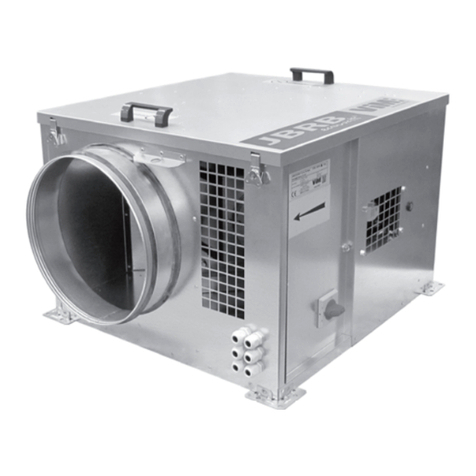
ViM JBRB ECOWATT User manual

NT00000704-JBRB-ECOWATT-AN-210301
INSTRUCTION MANUAL
INSTALLATION | WIRING | COMMISSIONING | MAINTENANCE |
AFNOR CERTIFICATION
ISO 14001
Environnement
AFNOR CERTIFICATION
ISO 9001
Qualité
JBRB ECOWATT®
Tertiary buildings ventilation ECM motor extractor unit
400°C 1/2hr C4 approved
Efectis certicate : EFR-16-002341
VENTIDRIVE Controller

2/28 NT00000704-JBRB-ECOWATT-AN-210301
CONTENTS
1. GENERAL INFORMATION ................................................................................................................ 3
1.1 Warnings .................................................................................................................................. 3
1.2 Safety instructions ................................................................................................................... 3
1.3 Reception - Storage.................................................................................................................. 3
1.4 Warranty .................................................................................................................................. 4
2. PRODUCT PRESENTATION.............................................................................................................. 4
2.1 Description................................................................................................................................ 4
2.2 Aeraulic curves ........................................................................................................................ 5
3. INSTALLATION .................................................................................................................................. 7
3.1 Dimensions and weight ........................................................................................................... 7
3.2 Handling ..................................................................................................................................11
3.3 Choice of location....................................................................................................................11
3.4 Ceiling-mounted installation ................................................................................................... 12
3.5 Accessories assembly............................................................................................................ 12
4. AERAULIC CONNECTION .............................................................................................................. 13
5. ELECTRICAL CONNECTION.......................................................................................................... 13
5.1 Prior precautions .................................................................................................................... 13
5.2 Electrical features .................................................................................................................. 14
5.3 Electrical connection of the local on-o switch ....................................................................... 14
5.4 Description of the drive for model 30 to 92............................................................................. 15
5.5 Pressure switch connection .................................................................................................. 16
5.6 Relay electrical connection..................................................................................................... 16
5.7 Relay functioning.................................................................................................................... 18
5.8 REB ECOWATT® or CVF remote electrical connection ......................................................... 19
5.9 BCCA 1V external Start/Stop control electrical connection in parallel
of the internal potentiometer................................................................................................... 20
5.10 Electrical wiring of the ETDZ (tactile command)..................................................................... 21
6. COMMISSIONING............................................................................................................................ 21
6.1 Prior precautions .................................................................................................................... 21
6.2 Setting the volume-pressure curve ........................................................................................ 21
7. MAINTENANCE................................................................................................................................ 23
7.1 Prior precautions .................................................................................................................... 23
7.2 Maintenance frequency.......................................................................................................... 23
7.3 Access to electric fan.............................................................................................................. 23
7.4 Electric fan replacement......................................................................................................... 24
7.5 Spare parts............................................................................................................................. 26
8. WASTE MANAGEMENT.................................................................................................................. 26
8.1 Treatment of packaging and general industrial waste (GIW) ................................................. 26
8.2 Treatment of Professional WEEE........................................................................................... 26
3/28 NT00000704-JBRB-ECOWATT-AN-210301
1. GENERAL INFORMATION
1.1 Warnings
This product has been manufactured according to rigorous technical rules of safety in conformity with EC
standards. The EC declaration may be downloaded from the Internet site (address given on the last page).
Before installing and using this product, carefully read these instructions, which contain important indi-
cations for your safety and the user’s safety during the installation, commissioning and maintenance of
this product. Once the installation is terminated, keep this manual handy nearby the machine for future
consultation.
This product must be installed (installation, connections, commissioning, maintenance) and all other inter-
ventions performed by a professional applying recognized good practice procedures, and respecting the
standards and safety regulations in force. The installation must be made in accordance with the prescrip-
tions indicated in the Electromagnetic Compatibility (EMC) and Low Voltage (LV) Directives.
We advise all people exposed to risks to scrupulously respect the accident prevention standards. The
manufacturer may not be held liable for any human injury and/or material damage resulting from the
non-respect of the safety instructions or from a change made on the product.
JBRB ECOWATT®units are intended for controlled mechanical ventilation or air recycling applications on
tertiary premises:
• Indoor or outdoor installation
• Environmental temperature: -20°C / +50°C
• Relative humidity: max. 95% without condensation
• Non-potentially-explosive atmosphere
• Low-salinity atmosphere, without corrosive chemical agents
1.2 Safety instructions
• Put on appropriate PPE (Personal Protective Equipment) before any work.
• Before installing the ventilation unit, make sure that the bracket and the location are strong enough
to bear the weight of the unit and any accessories.
• Do not open the access panels without having cut o the padlockable switch-disconnector included
in the unit.
• If work has to be carried out on the device, cut o the power supply on the main circuit breaker and
make sure that nobody can accidentally turn it back on.
• Make sure that moving parts are stationary.
• Check that the ventilation motor is not accessible via the connection brackets. (connection sheath
or protective shield).
Before starting, check the following points:
• Make sure that the device does not contain any foreign bodies.
• Check that all the components are mounted in their original positions.
• Check manually that the fans do not rub or get blocked.
• Check the connection of the earth electrode.
• Check that the access hatch is properly closed.
1.3 Reception - Storage
In case of short shipment, non-conformity, and/or total or partial damage to the products delivered, the
Buyer must, in accordance with article 133-3 of the French Commercial Code, add written reservations to
the carrier’s delivery slip and conrm them within 72 hours by registered letter with acknowledgement of
receipt with a duplicate for the seller. If the equipment is received without express reservation, the Buyer
has no subsequent recourse against us.
The product must be stored protected from weather, shocks and soiling due to splashing of any kind during
its transport from the supplier to the nal customer and on the site before installation.

4/28 NT00000704-JBRB-ECOWATT-AN-210301
1.4 Warranty
The equipment is guaranteed for 24 months from the invoice date. The warranty is limited to the re-
placement of parts or equipment whose operation is recognized as defective by maker, excluding any
compensation or penalties. The costs of labor, removal and rest, travel related to the replacement are the
responsibility of the Customer. Excluded from our warranty are defects linked to abnormal use or not in
accordance with the recommendations in our instructions, defects observed as a result of normal wear and
tear, incidents caused by negligence, lack of monitoring or maintenance, defects due to incorrect installa-
tion of devices or poor storage conditions prior to assembly.
In any case, maker is not responsible for transformed material, even partially repaired.
2. PRODUCT PRESENTATION
2.1 Description
The certicate number certies that the JBRB ECOWATT®range complies with the order of 22 March 2004
of the French Interior Ministry.
400°C 1/2hr C4 APPROVED Efectis certicate: EFR-16-002341.
• Galvanised steel sheet casing equipped with 4 mounting feet (size 04 to 38) or 2 omega cross-piec-
es (sizes 48 to 92).
• High performance galvanised steel backward.
• INTZ: installed/wired lockable safety switch.
• BDEZ: pressure switch installed, connected to the aeraulic network, to adjust on site.
• ECM direct-current motor outside airow:
-04 to 22: IP44 class B single-phase 230V, 50Hz,
-30, 38, 48, 70, 82: IP54, class F, single-phase 230V, 50Hz,
-30, 38, 48, 70, 92: IP54, class F, three-phase 400V, 50Hz.
-Equipped as standard with a potentiometer to adjust the unit’s operating point (0/10V command).
• Connection with circular brackets with class-D air duct seals. Vertical discharge version delivered
without connection brackets (optional PAPV sealed at bracket for installation with self-drilling
screws).
• Standard or insulated version (M0 re rating 25mm glass wool acoustic insulation).
• Cover equipped with handles, with tool-free removable using 4 quarter-turn systems.
• Horizontal or vertical discharge version.
• 3 available congurations: in-line, double inlet, modular: with elbow delivered with 1 stopper or 2 x
90° inlets.
Comment:
JBRB ECOWATT®models are equipped with an electronic-switching motor.
This motor is protected by:
- a built-in thermal protection on the motor winding,
- a thermistor built into the electronics.
These built-in motor protection systems have been tested and approved during re-resistance testing and certi-
ed C4 400°C 1/2hr.

5/28 NT00000704-JBRB-ECOWATT-AN-210301
2.2 Aeraulic curves
JBRB ECOWATT
®
04 JBRB ECOWATT
®
06
00
0 100 200 300 400 500
100
50
200 100
300 150
P(Pa)
stat
Δ
100%
75%
50%
Pabs (W)
Qv (m3/h)
42
42
41
68
69
70
0
100
200
300
400
0
50
100
150
200
0 100 200 300 400 500 600 700
P(Pa)
stat
Δ
Pabs (W)
100%
75%
50%
Qv (m3/h)
42
75
43
77
45
79
JBRB ECOWATT
®
10 JBRB ECOWATT
®
22
0
100
200
300
400
500
0
50
100
150
200
250
0 200 400 600 800 1000 1200
P(Pa)
stat
Δ
Pabs (W)
100%
75%
50%
Qv (m3/h)
41
73 38
71
37
71
Qv (m3/h)
0
100
200
300
400
500
600
0
100
200
300
400
500
600
0 500 1000 1500 2000 2500
P(Pa)
stat
Δ
Pabs (W)
100%
75%
50%
43
75 42
75
44
77
JBRB ECOWATT
®
30 JBRB ECOWATT
®
38
100%
75%
50%
Qv (m3/h)
0
100
200
300
400
500
600
700
0
100
200
300
400
500
600
700
0 500 1000 1500 2000 2500 3000 3500
P(Pa)
stat
Δ
Pabs (W)
47
77 45
76
48
78
100%
75%
50%
Qv (m3/h)
0
100
200
300
400
500
600
0
200
400
600
800
1000
1200
0 500 1000 1500 2000 2500 3000 3500 4000 4500
P(Pa)
stat
Δ
Pabs (W)
48
78 47
77
49
79

6/28 NT00000704-JBRB-ECOWATT-AN-210301
JBRB ECOWATT
®
48 JBRB ECOWATT
®
70
0 1000 2000 3000 4000 5000 6000
Qv (m3/h)
0
100
200
300
400
500 ∆P
stat
(Pa)
200
400
600
800
1000
Pabs (W)
100%
75%
50%
45
74 46
76
48
78
0
0 0
1000 2000 3000 4000 5000 6000 7000 8000
Qv (m3/h)
100
200
300
400
500
600
700 ∆P
stat
(Pa)
200
400
600
800
1000
1200
1400
Pabs (W)
100%
75%
50%
51
79 51
79
53
81
JBRB ECOWATT
®
82 JBRB ECOWATT
®
92
0
100
200
300
400
500
600
0
300
600
900
1200
1500
1800
0 1000 2000 3000 4000 5000 6000 7000 8000 9000
P(Pa)
stat
Δ
Pabs (W)
100%
75%
50%
Qv (m3/h)
50
80 49
78
52
81
0
100
200
300
400
500
600
700
800
0
300
600
900
1200
1500
1800
2100
2400
0 2000 4000 6000 8000 10000
P(Pa)
stat
Δ
Pabs (W)
100%
75%
50%
Qv (m3/h)
52
82 50
81
52
83

7/28 NT00000704-JBRB-ECOWATT-AN-210301
3. INSTALLATION
3.1 Dimensions and weight
JBRB ECOWATT
®
04 / 06 / 10 / 22 / 30 / 38 - horizontal discharge - L / M conguration
A
C
Ø D1
ØD1
B
C
I
J
B1
B
C
G
H
B1
E
F
Sense of the air
Sense of the airSense of the air
----- Only available
on modular version
(M conguration).
Model A B B1 C* D1 E F G H I J Weight (kg)
JBRB ECOWATT
®
04 627 523 533 320 160 568 502 157 175 157 161 21
JBRB ECOWATT
®
06 627 523 533 320 200 568 502 157 175 157 161 21
JBRB ECOWATT
®
10 627 566 583 421 250 569 544 207 185 207 186 26
JBRB ECOWATT
®
22 767 683 701 511 355 709 661 252 237 252 239 45
JBRB ECOWATT
®
30 1,019 820 873 568 400 892 797 267 271 267 271 64
JBRB ECOWATT
®
38 1,153 938 971 631 500 1,036 907 306 331 306 331 78
*IS version: +27mm
JBRB ECOWATT
®
48 / 70 / 82 / 92 - horizontal discharge - L / M conguration
H
G
C
F
C
Ø D1
A
Ø D1
E
J
I
C
F
B1
B
Sense of the air
Sense of the airSense of the air
----- Only available
on modular version
(M conguration).
Model A B B1 C* D1 E F G H I J Weight (kg)
JBRB ECOWATT
®
48 1,165 985 1,065 800 560 700 918 433 330 433 330 107
JBRB ECOWATT
®
70 1,280 1,030 1,100 880 630 815 970 473 365 473 365 121
JBRB ECOWATT
®
82 1,404 1,100 1,175 970 710 846 1,032 518 405 518 405 170
JBRB ECOWATT
®
92 1,404 1,100 1,175 970 710 846 1,032 518 405 518 405 170
*IS version: +27mm

8/28 NT00000704-JBRB-ECOWATT-AN-210301
JBRB ECOWATT
®
10 / 22 / 38 - horizontal discharge - D conguration
B
C
I
J
B
C
ØD2
ØD2
A
C
ØD1
G
H
E
F
Sense of the air
Sense of the air
Sense of the air
Model A B C* D1 D2 E F G H I J Weight (kg)
JBRB ECOWATT
®
10 815 603 421 250 200 777 544 194 161 207 186 32
JBRB ECOWATT
®
22 1,048 720 511 355 315 998 661 239 219 252 239 45
JBRB ECOWATT
®
38 1,468 1,024 631 500 400 1,396 908 306 281 306 331 83
*IS version: +27mm
JBRB ECOWATT
®
48 / 82 / 92 - horizontal discharge - D conguration
C
F
B
Ø D2
Ø D2
C
Ø D1
A
E
G
H
J
I
C
F
B
Sense of the air
Sense of the air
Sense of the air
Model A B C* D1 D2 E F G H I J Weight (kg)
JBRB ECOWATT
®
48 1,490 1,105 800 560 450 990 918 433 270 433 330 135
JBRB ECOWATT
®
82 1,813 1,237 970 710 560 1,016 1,032 518 340 518 405 200
JBRB ECOWATT
®
92 1,813 1,237 970 710 560 1,016 1,032 518 340 518 405 200
*IS version: +27mm

9/28 NT00000704-JBRB-ECOWATT-AN-210301
JBRB ECOWATT
®
04 / 06 / 10 / 22 / 30 / 38 - vertical discharge - L / M conguration
A
C
Ø D1
B
C
B1
B
C
G
H
B1
F
I
E
J Sense of the air
Sense of the air
Sense of the air
----- Only available
on modular version
(M conguration).
Model A B B1 C* D1 E F G H I J Weight (kg)
JBRB ECOWATT
®
04 609 523 533 320 160 568 502 157 175 130 165 21
JBRB ECOWATT
®
06 609 523 533 320 200 568 502 157 175 130 165 21
JBRB ECOWATT
®
10 616 566 583 421 250 569 544 207 185 166 198 26
JBRB ECOWATT
®
22 756 683 701 511 355 709 661 252 237 236 271 38
JBRB ECOWATT
®
30 973 820 873 565 400 892 797 267 271 248 286 64
JBRB ECOWATT
®
38 1,106 938 971 637 500 1,036 907 306 331 315 350 78
*IS version: +27mm
JBRB ECOWATT
®
48 / 70 / 82 / 92 - vertical discharge - L / M conguration
H
G
F
A
Ø D1
EF
B1
B
J
I
Sense of the air
Sense of the air
Sense of the air
----- Only available
on modular version
(M conguration).
Model A B B1 C* D1 E F G H I J Weight (kg)
JBRB ECOWATT
®
48 1,119 985 1,065 800 560 700 918 433 330 320 340 107
JBRB ECOWATT
®
70 1,234 1,030 1,100 880 630 815 970 473 365 370 375 121
JBRB ECOWATT
®
82 1,358 1,100 1,175 970 710 846 1,032 518 405 482 415 170
JBRB ECOWATT
®
92 1,358 1,100 1,175 970 710 846 1,032 518 405 482 415 170
*IS version: +27mm

10/28 NT00000704-JBRB-ECOWATT-AN-210301
JBRB ECOWATT
®
10 / 22 / 38 - vertical discharge - D conguration
B
C
I
J
B
C
ØD2
ØD2
A
C
ØD1
G
H
E
F
Sense of the air
Sense of the air
Sense of the air
Model A B C* D1 D2 E F G H I J Weight (kg)
JBRB ECOWATT
®
10 804 603 421 250 200 777 544 194 161 166 198 32
JBRB ECOWATT
®
22 1,037 720 511 355 315 998 661 239 219 236 271 45
JBRB ECOWATT
®
38 1,426 1,025 637 500 400 1,396 909 306 281 315 350 83
*IS version: +27mm
JBRB ECOWATT
®
48 / 82 / 92 - vertical discharge - D conguration
C
F
B
Ø D2
Ø D2
C
Ø D1
A
E
G
H
J
I
C
F
B
Sense of the air
Sense of the air
Sense of the air
Model A B C* D1 D2 E F G H I J Weight (kg)
JBRB ECOWATT
®
48 1,444 1,105 800 560 450 990 918 433 270 320 340 135
JBRB ECOWATT
®
82 1,767 1,237 970 710 560 1,016 1,032 518 340 482 415 200
JBRB ECOWATT
®
92 1,767 1,237 970 710 560 1,016 1,032 518 340 482 415 200
*IS version: +27mm

11/28 NT00000704-JBRB-ECOWATT-AN-210301
3.2 Handling
N.B.: Do not use the plastic handles to move the unit. These handles are only to open the unit
cover.
JBRB ECOWATT
®
04 to 38 JBRB ECOWATT
®
48 to 92
3.3 Choice of location
JBRB ECOWATT
®
04 to 38 JBRB ECOWATT
®
48 to 92
C
C
C
C
C
C
Leavethe heightofthe unitabove theunitandonthe doorside fordevicecommissioning andmaintenance.

12/28 NT00000704-JBRB-ECOWATT-AN-210301
3.4 Ceiling-mounted installation
JBRB ECOWATT
®
04 to 38 Ceiling-mounted installation
100
C
C
JBRB ECOWATT®04 to 38 can be installed with the
cover facing downwards.
• Air space of at least 100mm must be main-
tained between the unit and the horizontal sur-
face on which it is set up.
• Horizontal discharge: unconditionally author-
ised.
• Vertical discharge: authorised if connected to
an aeraulic network.
• The unit fastening mode must be sucient to
ensure it is held well in place in case of re.
3.5 Accessories assembly
3.5.1 Circular connection to discharge
Fasten the sealed at bracket using 6 self-drilling screws (not supplied).
For a unit not connected to discharge, add a vent cowl (CP) to enable 360° exhaust air outlet around
the vertical discharge axis. According to the NF DTU 68.3 P 1-1-1 standard, the CP makes it possible to
eliminate the eects of the wind and not add 20Pa of additional pressure drop.

13/28 NT00000704-JBRB-ECOWATT-AN-210301
4. AERAULIC CONNECTION
The unit must be fastened to a very at surface, using the holes drilled in the mounting feet or the omega
bars provided for this purpose. Installation on anti-vibration supports and connection with exible connec-
tors are recommended.
L
In line
M
Modular
D
Double inlet
90° elbow 90° double inlet
Horizontal
discharge
En ligne
L
Double aspiration
D
Modulable coudé à 90° /
double aspiration à 90°
M
Orientation
rejet
horizontal
Orientation
rejet
vertical
En ligne
L
Double aspiration
D
Modulable coudé à 90° /
double aspiration à 90°
M
Orientation
rejet
horizontal
Orientation
rejet
vertical
En ligne
L
Double aspiration
D
Modulable coudé à 90° /
double aspiration à 90°
M
Orientation
rejet
horizontal
Orientation
rejet
vertical
En ligne
L
Double aspiration
D
Modulable coudé à 90° /
double aspiration à 90°
M
Orientation
rejet
horizontal
Orientation
rejet
vertical
En ligne
L
Double aspiration
D
Modulable coudé à 90° /
double aspiration à 90°
M
Orientation
rejet
horizontal
Orientation
rejet
vertical
Vertical
discharge
En ligne
L
Double aspiration
D
Modulable coudé à 90° /
double aspiration à 90°
M
Orientation
rejet
horizontal
Orientation
rejet
vertical
En ligne
L
Double aspiration
D
Modulable coudé à 90° /
double aspiration à 90°
M
Orientation
rejet
horizontal
Orientation
rejet
vertical
En ligne
L
Double aspiration
D
Modulable coudé à 90° /
double aspiration à 90°
M
Orientation
rejet
horizontal
Orientation
rejet
vertical
En ligne
L
Double aspiration
D
Modulable coudé à 90° /
double aspiration à 90°
M
Orientation
rejet
horizontal
Orientation
rejet
vertical
En ligne
L
Double aspiration
D
Modulable coudé à 90° /
double aspiration à 90°
M
Orientation
rejet
horizontal
Orientation
rejet
vertical
The setup of this unit’s aeraulic system and its network must meet the technical conditions dened in the
NF DTU 68-3 standard in case of installation of collective controlled mechanical ventilation.
Connection diameters:
Model L, M, D discharge L, M inlet D inlet
JBRB ECOWATT
®
04 160 160 -
JBRB ECOWATT
®
06 200 200 -
JBRB ECOWATT
®
10 250 250 200
JBRB ECOWATT
®
22 355 355 315
JBRB ECOWATT
®
30 400 400 -
JBRB ECOWATT
®
38 500 500 400
JBRB ECOWATT
®
48 560 560 450
JBRB ECOWATT
®
70 630 630 -
JBRB ECOWATT
®
82 710 710 560
JBRB ECOWATT
®
92 710 710 560
5. ELECTRICAL CONNECTION
5.1 Prior precautions
Models 30 to 92:
This electronic-switching motor cannot be powered directly by mains power, on pain of destruction. Its
power must be supplied by the controller.
The device must be turned on and o via the factory-wired REB ECOWATT®on the controller’s Start/Stop
terminals. Do not turn o the device by directly shutting o the controller’s power supply via the INTZ or
shutting o the mains power supply.
Short circuit protection
The JBRB ECOWATT®power supply must have a short circuit protection. The short circuit protection
equipment must at least have a "C" curve trigger according to IEC 60898-1.

14/28 NT00000704-JBRB-ECOWATT-AN-210301
5.2 Electrical features
Size Single-phase 230V Three-phase 400V
Turbine Input power
(kW) I. Max
(A) Turbine Input power
(kW) I. Max
(A)
JBRB ECOWATT
®
04 160 0.07 0.7
JBRB ECOWATT
®
06 160 0.13 1.0
JBRB ECOWATT
®
10 225 0.15 1.2
JBRB ECOWATT
®
22 280 0.35 1.6
JBRB ECOWATT
®
30 315 0.60 2.6 315 0.60 1.2
JBRB ECOWATT
®
38 355 0.70 3.1 355 0.70 1.3
JBRB ECOWATT
®
48 400 0.72 3.1 400 0.72 1.5
JBRB ECOWATT
®
70 450 1.24 5.4 450 1.24 2.6
JBRB ECOWATT
®
82 500 1.40 6.0
JBRB ECOWATT
®
92 500 1.70 3.5
5.3 Electrical connection of the local on-o switch
The on-o switch is used to isolate the device from the power supply in case of maintenance, or
to turn the device on/o.
JBRB ECOWATT
®
04 to 22 Single-phase
NL
JBRB ECOWATT
®
30 to 82 Single-phase
NL
JBRB ECOWATT
®
30 to 92 Three-phase
L1 L2 L3
To access the on-o switch’s terminals, unscrew the door’s 2 M8 screws using a 13mm spanner.
Add a cable gland to the power cable and connect it to the on-o switch terminals.

15/28 NT00000704-JBRB-ECOWATT-AN-210301
5.4 Description of the drive for model 30 to 92
UVWPEBR- BR+
A
B
Gnd
+10V
0-10V
GND
D2
D1
D0
Gnd
R2No
R2C
R2Nc
R1No
R1C
R1Nc
Gnd
+24V
+10V
AO_1
DI_4
DI_3
AI_2
Therm
Gnd
A
B
C
LNPE L1 L2 PE
L3
Terminal block accessible
under the blue cover by
means of 6 TX20 screws
Motor connection
Factory made
Command terminal block
Control connection
PE M25 Multipass
3 passes - 2 available
Cable sheath Ø 6.8 to 9 mm
Power connection
Factory-made to INTZ
Factory-tted motor terminal block
It is imperative that the U-V-W
cable sequence is observed. Factory-tted terminal block
One-phase Three-phase
Running status LED
RJ 12 - Modbus connectors
Command terminal block
The various control functions are
dened in the operating instructions.
A
B
Gnd
+10V
0-10V
GND
D2
D1
D0
Gnd
R1 C
R1 Nc
Gnd
+24V
+10V
AO_1
DI_4
DI_3
AI_2
Therm
Gnd
R2 No
R2 C
R2 Nc
R1 No
Modbus
Speed control via analogue input 0-10V
REB ECOWATT (potentiometer and ON/OFF function)
factorywired
Digital On/O input (Shunt wired from factory)
Digital input Reset alarm
Not used
Outlet +24V
Outlet +10V
Total consumption
max 450mA
0-10V outlet, representative of the motor speed
Digital input disabled
Digital input Fire mode (Thermocontact wired from factory)
1
2
3
4
5
6
7
8
9
10
25
24
23
22
21
20
19
18
17
16
15
14
13
12
11
No function
Output 1 relay
Running relay
Output 2 relay
Fault relay
Max 1A at
30VDC and 24VAC

16/28 NT00000704-JBRB-ECOWATT-AN-210301
5.5 Pressure switch connection
• Open the unit panel by unscrewing both screws with a 13mm spanner.
• Add the 2nd cable gland to the cable.
• Open the pressure switch cowl and connect the wires.
• Access to terminals and settings
• Lightly lift to remove the base plate cover
1
2
3
Ventilation fault indicator light
Normal operation indicator
light
Max. 250Vac power supply
Adjusting disk
State of contact at rest
1
23
Switches for measurement
of pressure ΔP > at threshold
ΔP0 of pressure switch setting
Interrupting
capacity
Resistive load
(cos Ø=1) Inductive load
(cos Ø=0.6) Mechanical
lifespan Cable
gland Protection
index Pressure
connection Mass
Under 250Vac Under 30Vac Under 250Vac Under 30Vac > 10 million
cycles 1xPg11 IP54 with
cowl Ø6.2mm Approx.
10 g
5A 4A 0.8A 0.7A
5.6 Relay electrical connection
5.6.1 Functioning status alarm and indication
LED Indication
A LED near the PE, under the drive is present.
• Green constant LED: power supply is wired.
• Green ashing LED: Modbus communication is active.
• Red constant LED: at least one critical alarm is active.
• Red ashing LED: a non-critical alarm is active.

17/28 NT00000704-JBRB-ECOWATT-AN-210301
Alarms table
Alarms view Trigger Motor function / action
Power supply too low The power supply is too low Reduced performance
Power supply too high The power supply is too high Stop of the motor after 5 restarts caused
by the same default during 60 minutes
Electronic internal temperature too high
(>95°C) The ambient temperature is too high
around the drive Reduced performance
Phases error: one or several phases
disconnected (L1, L2, L3) Missing phase
Unbalance between phases Stop of the motor after 5 restarts caused
by the same default during 60 minutes
Blocked rotor The rotor cannot round because of a
rotor or wheel mechanical blocking Stop of the motor after 5 restarts caused
by the same default during 60 minutes
Error of the phases in motor power
supply (U, V, W) One or several phases/ one or several
motor wires are disconnected Stop of the motor after 5 restarts caused
by the same default during 60 minutes.
24 VDC external power supply
overloaded Overload or short circuit of the +24V
power supply Reduced performance
Alarm reset by the connection block
Once the problem solved, you can reset an alarm by closing the contact between DI2 (connection 7) and
GND (connection 6), an impulse is sucient.
Review of alarms and reset by ETDZ (option).
ETDZ wires on the RJ12 “A” Modbus connector of the terminal block.
ETDZ (tactile command) allows to obtaining some precise information on the alarm type.
You can consult a reset an alarm via ETDZ, by following these instructions:
Setpoint 0%
Current speed _ _ _ RPM
Drive type PM
Drive power in _ _ _ kW
Control type 0-10V
Warning & alarms
RESET
ALARM/WARNING DESCRIPTION
Alarm 1001
Motor stop due to alarm
Alarm 1202
One or more lacking phases in motor
connection (U, V, W)
A bell appears on the left up of the screen, press to consult
the alarms. After solving the problem, press RESET.

18/28 NT00000704-JBRB-ECOWATT-AN-210301
5.7 Relay functioning
Relays characteristics
Max 1A under 30VDC and 24 VAC
The Output 1 relay is a running relay.
The relay switches when the run signal is given.
The Output 2 relay is a fault relay.
The relay switches when the motor stops after 5 attempts of restart.
CONTROLLER TERMINALS
R2 No
R2 C
R2 Nc
R1 No
R1 C
R1 Nc
25
24
23
22
21
20
Output 1 relay
Running relay
Output 2 relay
Fault relay
Max 1A at
30VDC and 24VAC 30VDC / 24VAC
Power on request indicator
Fault or power o indicator
GND
GND
Modication relays functions using ETDZ (Option)
ETDZ wires on the RJ12 “A” Modbus connector of the terminal block.
ETDZ (tactile command) allow the modication of the relay functioning.
Other functioning:
Running spin: the relay switches when the minimum fan speed is reached.
Single error alarm: the relay switches at the rst error (rst attempt of reset).
Setpoint 0%
Current speed _ _ _ RPM
Drive type PM
Drive power in _ _ _ kW
Control type 0-10V
Status
Drive setup
User settings
I/O
Warnings & alarms
Modbus
Conguration
Software
MENU
Digital in 3
Option 1
Option 2
I/O
Digital in 1
Digital in 2
Digital out
Digital in 4
Thermistor threshold 0Ω
Alarm
Modbus controlled
Single error alarm
OPTION 1
Disabled
Running start
Running spin
Output
Press the 3 horizontal lines
at the top right of the screen
to access the menu
Press I/O Press Option 1 to modify
the Output 1 relay function
Press Option 2 to modify
the Output 2 relay function
Select the desired function
Return to the home screen
by pressing 3 times on the
top left arrow
ETDZ - HOME SCREEN

19/28 NT00000704-JBRB-ECOWATT-AN-210301
5.8 REB ECOWATT®or CVF remote electrical connection
• Speed set by remote potentiometer, select the desired curve by referring to § "2.2 Aeraulic curves",
page 5.
• Disconnect the potentiometer built into the unit to connect the “CVF or REB ECOWATT®” remote
potentiometer instead.
JBRB ECOWATT
®
04 to 22 single-phase wiring
Lockable
safety switch
REB ECOWATT®
CVF
Gnd
Consigne 0-10V
+10V
L
N
LN
12345
P
JBRB ECOWATT
®
30 to 92 single-phase or three-phase wiring
12345
P
CONTROLLER
TERMINALS
A
B
Gnd
+10V
0-10V
GND
D2
D1
D0
Gnd
1
2
3
4
5
6
7
8
9
10
CVF
Accessory not provided
ON/OFF
Voltage
supply
Output
signal
GND

20/28 NT00000704-JBRB-ECOWATT-AN-210301
5.9 BCCA 1V external Start/Stop control electrical connection in parallel
of the internal potentiometer
• Speed set by remote potentiometer, select the desired curve by referring to §"2.2 Aeraulic curves",
page 5
• The BCCA 1V external Start/Stop control enables to stop the JBRB ECOWATT® cabinet fan without
modifying the initial airow/pressure step point.
JBRB ECOWATT
®
04 to 22 single-phase or three-phase wiring
M
+10V
Entrée 0-10V
Gnd
N
L
Thermocontact
N/O
Thermocontact
N/O
Interrupteur
REB ECOWATT
+10V
Consigne0-10V
Gnd
Lockable
safety switch
12345
P
CVF
NL
N
L
Stop / Start 13
14
33
34
JBRB ECOWATT
®
30 to 92 single-phase or three-phase wiring
12345
P
CONTROLLER
TERMINALS
A
B
Gnd
+10V
0-10V
GND
D2
D1
D0
Gnd
1
2
3
4
5
6
7
8
9
10
CVF
Accessory not provided
13
34
14
33
BCCA 1V
Accessory not provided
ON/OFF
Voltage supply
Output signal
GND
Other manuals for JBRB ECOWATT
1
Table of contents
Other ViM Scrubber manuals
Popular Scrubber manuals by other brands

Fimap
Fimap MR65 B Use and maintenance manual

Windsor
Windsor Saber Compact SC20 operating instructions

Kärcher
Kärcher Windsor Chariot 2 iScrub 20 operating instructions

Nilfisk-Advance
Nilfisk-Advance Advance SC900 ST-28D Instructions for use

Nilfisk-Advance
Nilfisk-Advance SR 1000S B Instructions for use

Nilfisk-Advance
Nilfisk-Advance SC3500 quick start guide