Vimar BY-ALARM PLUS User manual

Viale Vicenza, 14
36063 Marostica VI - Italy
www.vimar.com
49401661A0 01 2212
03810
BY-ALARM PLUS
Modulo comunicatore GSM By-alarm Plus, configurabile per invio/ricezione di
messaggi SMS, invio messaggi vocali, notifiche in protocollo SIA-IP, conteni-
tore plastico non protetto.
Il dispositivo consente di inviare automaticamente, attraverso la rete GSM e a qualunque numero
di telefono, tutte le comunicazioni di allarme, di guasto o anomalia, con le modalità che seguono:
• Chiamate vocali utilizzando la scheda vocale 03813 installata in centrale.
• Trasmissione eventi SIA-IP
• Invio SMS per ciascun evento utilizzando la descrizione fornita dal registro eventi di tastiera
Il dispositivo può comunicare con la centrale a seguito della ricezione dei comandi attivati nei
seguenti modi:
- SMS inviati dall'utente;
- chiamata da numero/i di telefono utente configurati (CALLER-ID).
Il comunicatore utilizza la tecnologia "VoLTE" per effettuare chiamate vocali attraverso la rete 4G.
Se tale tecnologia non è attivata il dispositivo utilizza automaticamente la rete disponibile (3G
o 2G).
Attenzione: Non si garantisce la piena disponibilità di tutte le funzioni inerenti ai servizi mobile
descritte per qualsiasi combinazione di fornitore, tipologia di SIM e modello di apparecchio
telefonico utilizzati.
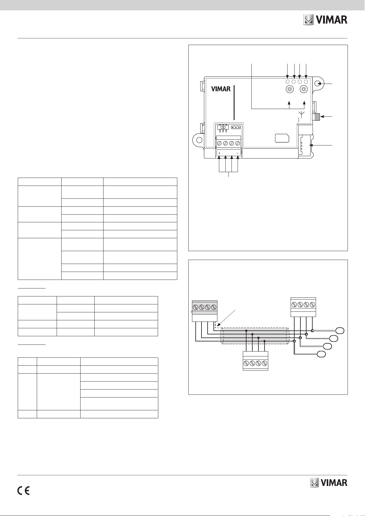
COLLEGAMENTI
Il collegamento con la centrale va effettuato con un cavo schermato a 4 (o più) fili.
Attenzione: La calza va collegata ad uno dei morsetti di massa (o GND) solo dal lato della
centrale e deve seguire tutto il BUS senza essere collegata a massa in altri punti.
Il collegamento della scheda va effettuato sui morsetti “+ D S -” della centrale.
Collegare il cavo dell'antenna al connettore "H".
SEGNALAZIONI DEI LED E PULSANTI
Led Modalità Significato
L1 - Comunicazione
Verde
Lampeggiante Comunicazione con la centrale in corso
Spento Assenza di comunicazione
L2 - Emergenza
Rosso
Lampeggiante Sabotaggio in corso o guasto nel bus
Spento Nessun sabotaggio o guasto
L3 - Guasti
Verde
Lampeggiante Guasto del comunicatore
Spento Nessun guasto
L4 - Connessione
Rosso
Lampeggio lento Dispositivo registrato nella rete GSM
Lampeggio moderato Dispositivo non registrato e in ricerca
dell’operatore
Lampeggio veloce Scambio dati in corso
Spento Comunicatore spento
Pulsante P1
Premere il pulsante P1 per visualizzare il livello di segnale attraverso l'accensione dei led. La
visualizzazione dura 5 s.
Led Modalità Significato
L1 Lampeggiante Segnale insufficiente
Acceso Segnale debole
L1 + L2 Accesi Segnale buono
L1 + L2 + L3 Accesi Segnale ottimo
Pulsante P2
In caso di accensione del led L3 e quindi in presenza di un guasto, premere il pulsante P2 per
conoscerne la causa attraverso i led L1, L2 e L3.
Led Modalità Significato
Lampeggiante Batteria scarica
L2 Lampeggiante
Mancato sblocco della scheda SIM
Scheda SIM mancante
Segnale insufficiente
Dispositivo non registrato con l'operatore
mobile
L3 Accesi Segnale ottimo
VISTA FRONTALE
A: Morsetti +, D, S, - per il collegamento del BUS
B: Pulsanti P1 e P2
C: Led L1 - Comunicazione
D: Led L2 - Emergenza
E: Led L3 - Guasti
F: Led L4 - Connessione
G: Foro di fissaggio
H: Connettore per antenna
I: Alloggiamento per scheda SIM
A
C
COLLEGAMENTI
INSTALLAZIONE
Il modulo comunicatore 03810 non dispone di protezione antisabotaggio integrata ed espone i
cavi utilizzati ad eventuali manomissioni.
E' dunque opportuno proteggere i collegamenti e il dispositivo stesso installandolo dentro una
scatola, ossia:
• scatola della centrale utilizzando gli appositi fori
• scatola di derivazione
• quadro elettrico
Nota: Ai fini della conformità alla norma 50131, l'involucro utilizzato ed il dispositivo devono
essere dotati di una protezione anti-sabotaggio.
SIM CARD
SIM CARD
ANTENNA
P1
L4L3L2L1
P2
D
2
S
31 4
4G PHONE DIALER
03810
By-alarm Plus
D E F
G
H
I
B
D+ –S
D+ –S
D+ –S
S
–
D
+
Centrale
03800
03801
03802
BUS
Calza
Altri dispositivi
BUS
Modulo
comunicatore
03810

Viale Vicenza, 14
36063 Marostica VI - Italy
www.vimar.com
49401661A0 01 2212
SIM CARD
D
2
S
31 4
SIM CARD
ANTENNA
P1
L4L3L2L1
P2
4G PHONE DIALER
03810
By-alarm Plus
1.Scegliere la posizione idonea all’installazione del dispositivo e dell'antenna. In caso di utilizzo
della scatola della centrale, togliere l'alimentazione disconnettendo sia la rete (230 V~) che la
batteria tampone.
2. Fissare il dispositivo all'interno della scatola. In caso di utilizzo della scatola della centrale,
avvitare il contenitore di plastica ai fori filettati del fondo.
3. Inserire la scheda SIM.
4. Cablare l’antenna.
5. Cablare il comunicatore.
6. Effettuare la procedura di configurazione del dispositivo. Il lampeggio del led L1 indica che
il comunicatore è stata acquisito dalla centrale e sta comunicando correttamente con essa.
7.Posizionare l’antenna nel punto dove il livello di segnale è migliore. Il livello di segnale è visua-
lizzabile sia mediante il pulsante P1 che con il software By-alarm Manager Plus.
9.Attendere il lampeggio del led L4 che segnala l'effettiva registrazione alla rete o un trasferimen-
to dati.
10. Mediante il software By-alarm Manager Plus verificare che il servizio "VoLTE" sia attivo; in
caso contrario rivolgersi all’operatore telefonico per attivarlo.
11. Richiudere la scatola. In caso di utilizzo della scatola della centrale, ripristinare l'alimentazione
da rete (230 V~) e ricollegare la batteria tampone.
CONFIGURAZIONE
Per tutti i dettagli si vedano i manuali di installazione del sistema By-Alarm Plus e del software
By-alarm Plus Manager.
REGOLE DI INSTALLAZIONE
L’installazione e la configurazione devono essere effettuate da personale qualificato con l’osser-
vanza delle disposizioni regolanti l’installazione del materiale elettrico in vigore nel paese dove i
prodotti sono installati.
CARATTERISTICHE
• Tensione di alimentazione dal bus: da 9 a 15 V
• Corrente assorbita
- in stanby: 70 mA
- in chiamata: 540 mA max
• Range di frequenza: 800 MHz, 1800 MHz, 2100 MHz e 2600 MHz
• Potenza RF trasmessa:
- per il 2 e 3G: 2 W (33 dBm)
- per il 4G: 200 mW (23 dBm)
• Antenna: 1,5 m di cavo, connettore SMA-Male e base magnetica
• Temperatura di funzionamento: da -10 a +40 °C
• Umidità relativa: ≤75% senza condensazione
• Grado di sicurezza: 3
• Classe d’isolamento: II
• Dimensioni (L x A x P): 108 x 64 x 24 mm
• Peso: 77 g
CONFORMITA' NORMATIVA.
Direttiva RED. Direttiva RoHS.
Norme EN 301 489-52, EN 301 511, EN 62311, EN 62368-1, EN 50130-4, EN 50130-5, EN
55032, EN 50131-3, EN 50131-10, EN 50136-2, EN IEC 63000.
Vimar SpA dichiara che l’apparecchiatura radio è conforme alla direttiva 2014/53/UE. Il testo
completo della dichiarazione di conformità UE è disponibile nella scheda di prodotto al seguente
indirizzo Internet: www.vimar.com.
Regolamento REACh (UE) n. 1907/2006 – art.33. Il prodotto potrebbe contenere tracce di
piombo.
RAEE - Informazione agli utilizzatori
Il simbolo del cassonetto barrato riportato sull’apparecchiatura o sulla sua confezione indica che il prodotto alla fine della
propria vita utile deve essere raccolto separatamente dagli altri rifiuti. L’utente dovrà, pertanto, conferire l’apparecchiatura
giunta a fine vita agli idonei centri comunali di raccolta differenziata dei rifiuti elettrotecnici ed elettronici. In alternativa alla
gestione autonoma, è possibile consegnare gratuitamente l’apparecchiatura che si desidera smaltire al distributore, al mo-
mento dell’acquisto di una nuova apparecchiatura di tipo equivalente. Presso i distributori di prodotti elettronici con superficie
di vendita di almeno 400 m2è inoltre possibile consegnare gratuitamente, senza obbligo di acquisto, i prodotti elettronici
da smaltire con dimensioni inferiori a 25 cm. L’adeguata raccolta differenziata per l’avvio successivo dell’apparecchiatura
dismessa al riciclaggio, al trattamento e allo smaltimento ambientalmente compatibile contribuisce ad evitare possibili ef-
fetti negativi sull’ambiente e sulla salute e favorisce il reimpiego e/o riciclo dei materiali di cui è composta l’apparecchiatura.
Viale Vicenza, 14
36063 Marostica VI - Italy
www.vimar.com
49401661A0 01 2212
03810
BY-ALARM PLUS
By-alarm Plus GSM communicator module, can be configured to send/receive
SMS messages, voice messages and alerts are sent with the SIA-IP protocol,
unprotected plastic enclosure.
The device automatically sends all alarm, malfunction or fault communications to any phone
number via the GSM network as follows:
• Voice calls using the voice board 03813 installed in the control unit
• Transmitting SIA-IP events
• Sending text message for each event using the description provided in the keypad event log
The device can communicate with the control unit, and can receive controls sent as follows:
- text messages sent by the user;
- calls from configured user telephone numbers (CALLER-ID).
The communicator uses "VoLTE" technology to make voice calls over the 4G network.
If this technology is not activated, the device automatically uses the available network (3G or 2G).
Caution: We cannot guarantee that all the mobile service functions described will be available
for any specific combination of provider, SIM type and telephone equipment model used.
CONNECTIONS
Connect it to the control unit with a 4-wire (or more) shielded cable.
Caution: Connect the shield to one of the earth (or GND) terminals at the control unit end only,
and ensure that it follows the entire BUS without being connected to earth at any other point.
Connect the board to the “+ D S -” terminals on the control unit.
Connect the antenna cable to connector "H".
LED INDICATIONS AND PUSH BUTTONS
LED Mode Meaning
L1 - Communication
Green
Flashing Communication with the control unit
active
Off No communication
L2 - Emergency
Red
Flashing Tampering in progress or bus fault
Off No tampering or fault
L3 - Faults
Green
Flashing Communicator fault
Off No fault
L4 - Connection
Red
Slow flashing Device registered on the GSM network
Medium flashing Device not registered and searching for
an operator
Fast flashing Data exchange in progress
Off Communicator off
Push button P1
Press push button P1 to display the signal level on the LEDs. The display lasts 5 s.
LED Mode Meaning
L1 Flashing Insufficient signal
On Weak signal
L1 + L2 On Good signal
L1 + L2 + L3 On Excellent signal
Push button P2
If LED L3 is on, meaning that there is a fault, press push button P2 to display the cause on LEDs
L1, L2 and L3.
LED Mode Meaning
L1 Flashing Flat battery
L2 Flashing
SIM card not unlocked
No SIM card
Insufficient signal
Device not registered with the mobile
operator
L3 On Excellent signal
FRONT VIEW
A
C
CONNECTIONS
SIM CARD
SIM CARD
ANTENNA
P1
L4L3L2L1
P2
D
2
S
31 4
4G PHONE DIALER
03810
By-alarm Plus
D E F
G
H
I
B
D+ –S
D+ –S
D+ –S
S
–
D
+
Control unit
03800
03801
03802
BUS
Shield
Other devices
BUS
Communicator
module
03810
INSTALLATION
The communicator module 03810 does not have built-in anti-tamper protection and exposes
the cables used to tampering.
It is therefore good practice to protect the connections and the device by installing them inside
a box, i.e.:
• the control unit box, using the holes provided
• a junction box
• the switchboard
Note: To ensure compliance with standard 50131, the casing used and the device must be
equipped with anti-tamper protection.
A: +, D, S, - terminals for connecting the BUS
B: Push buttons P1 and P2
C: LED L1 - Communication
D: LED L2 - Emergency
E: LED L3 - Fault
F: LED L4 - Connection
G: Fixing hole
H: Connector for antenna
I: SIM board housing

Viale Vicenza, 14
36063 Marostica VI - Italy
www.vimar.com
49401661A0 01 2212
SIM CARD
D
2
S
31 4
SIM CARD
ANTENNA
P1
L4L3L2L1
P2
4G PHONE DIALER
03810
By-alarm Plus
1. Choose a suitable location to install the device and antenna. When using the control unit box,
power it down and disconnect the mains power (230 V~) and the buffer battery.
2. Fasten the device inside the box. When using the control unit box, screw the plastic enclosure
to the threaded holes on the bottom.
3. Insert the SIM card.
4. Wire the antenna.
5. Wire the communicator.
6. Perform the device configuration procedure. LED L1 will flash to indicate that the control unit
has acquired the communicator and that they are communicating correctly.
7.Position the antenna where the signal level is best. The signal level can be seen by pressing
push button P1 or via the By-alarm Manager Plus software.
9.Wait for LED L4 to flash, which indicates successful network registration or data transfer.
10. Use the By-alarm Manager Plus software to check that the "VoLTE" service is active; if not,
contact the telephone operator to activate it.
11. Close the box. When using the control unit box, restore the mains power (230 V~) and
reconnect the buffer battery.
CONFIGURATION
Refer to the By-Alarm Plus control unit manual and the By-Alarm Plus Manager software manual
for all the details.
INSTALLATION RULES
Installation and configuration must be carried out by qualified personnel in compliance with the
current regulations regarding the installation of electrical equipment in the country where the
products are installed.
CHARACTERISTICS
• Power supply voltage from the bus: 9 to 15 V
• Absorbed current
- in standby: 70 mA
- during a call: 540 mA max
• Frequency range: 800 MHz, 1800 MHz, 2100 MHz and 2600 MHz
• RF transmission power:
- for 2G and 3G: 2 W (33 dBm)
- for 4G: 200 mW (23 dBm)
• Antenna: 1.5 m cable, SMA-Male connector and magnetic base
• Operating temperature: -10 to +40 °C
• Relative humidity: ≤75% non-condensing
• Safety class: 3
• Insulation class: II
• Dimensions (W x H x D): 108 x 64 x 24 mm
• Weight: 77 g
REGULATORY COMPLIANCE.
RED directive. RoHS directive.
Standards EN 301 489-52, EN 301 511, EN 62311, EN 62368-1, EN 50130-4, EN 50130-5, EN
55032, EN 50131-3, EN 50131-10, EN 50136-2, EN IEC 63000.
Vimar SpA declares that the radio equipment complies with Directive 2014/53/EU. The full text
of the EU declaration of conformity is on the product sheet available on the following website:
www.vimar.com.
REACH (EU) Regulation no. 1907/2006 – Art.33. The product may contain traces of lead.
WEEE - User information
The crossed bin symbol on the appliance or on its packaging indicates that the product at the end of its life must be collected
separately from other waste. The user must therefore hand the equipment at the end of its life cycle over to the appropri-
ate municipal centres for the differentiated collection of electrical and electronic waste. As an alternative to independent
management, you can deliver the equipment you want to dispose of free of charge to the distributor when purchasing a
new appliance of an equivalent type. You can also deliver electronic products to be disposed of that are smaller than 25
cm for free, with no obligation to purchase, to electronics distributors with a sales area of at least 400 m2. Proper sorted
waste collection for subsequent recycling, processing and environmentally conscious disposal of the old equipment helps
to prevent any possible negative impact on the environment and human health while promoting the practice of reusing and/
or recycling materials used in manufacture.
Other manuals for BY-ALARM PLUS
19
This manual suits for next models
1
Table of contents
Languages:
Other Vimar Cell Phone manuals


