Viale Vicenza, 14
36063 Marostica VI - Italy
www.vimar.com
46235.016B
49401248A0 00 1802
IT EN
HP Audio Out
Network Port
MIC IN
Power
DC12V
1
2
3
4
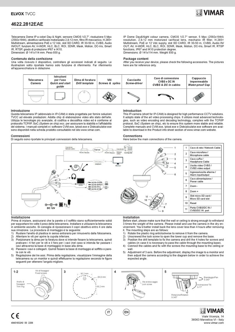
Installazione scheda TF e collegamento dell’alimentazione
Installare la scheda di archiviazione:
1 - Allentare le viti sse come illustrato di seguito (Fig. 1).
2 - Inserire la scheda TF nello slot della scheda di archiviazione (Fig. 2).
3 - Rimontare la cupola.
Installazione telecamera
Prima di iniziare, assicurarsi che la parete o il sotto siano sucientemente solidi
per sopportare il peso della telecamera. Installare e utilizzare la telecamera
in ambiente asciutto. La procedura di montaggio è la seguente:
1- Passare i cavi attraverso la staa. Montare la speed dome sulla staa (Fig. 3).
2- Fissare la speed dome alla staa con le viti (Fig. 4)
3- Utilizzare la dima di foratura per praticare i fori per le viti sulla parete.
4- Allineare le due viti ai fori indicati dalle frecce e lasciare circa 12 mm dal muro
(Fig. 5-6)
5- Collegare i cavi e quindi appendere la staa al muro e ssarla (Fig. 7-8).
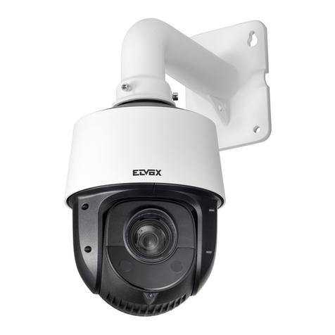
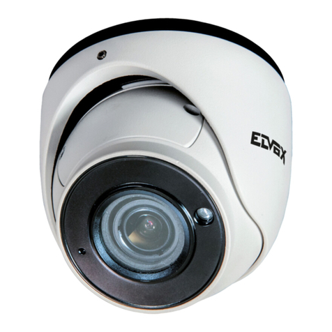
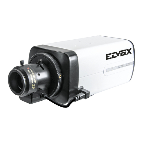
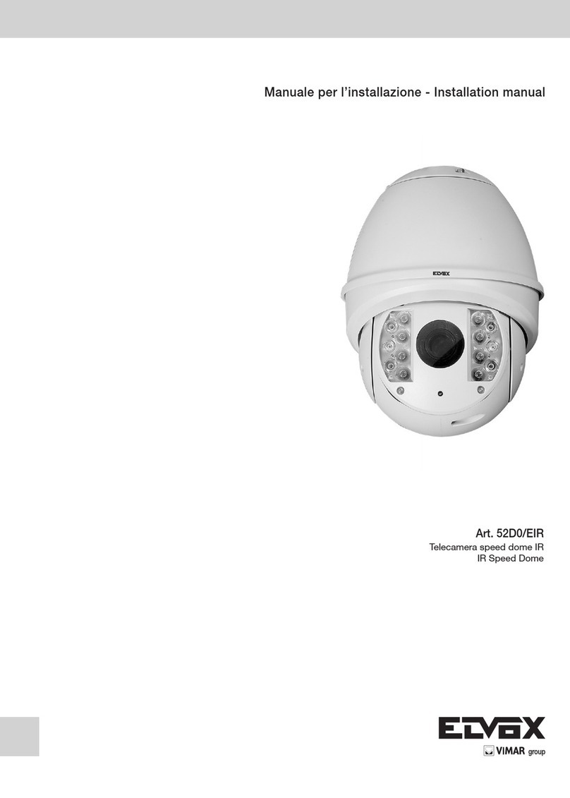
Telecamera Speed Dome IP 2 Mpx (1920x1080), sensore CMOS 1/2,8", obiettivo
5.5 ~ 88 mm, ltro IR meccanico, zoom ottico 16x, illuminatori IR con portata no
a 50 m, slot SD CARD, funzioni WDR, BLC, Defog e 3DNR, RTSP, protocollo ON-
VIF, alimentazione 12 Vdc max 30 W con IR ON, completa di staa da parete e
alimentazione, grado di protezione IP66. Dimensioni senza staa ø136x222 mm.
Peso 1700 g.
Introduzione
Questa telecamera IP Speed Dome è stata progettata per fornire soluzioni TVCC
ad elevate prestazioni. La tecnologia di ip digitale consente di riprendere immagini
in tutte le direzioni e monitorare senza punti ciechi. Adotta chip di elaborazione
video allo stato dell'arte. Utilizza le tecnologie più avanzate di codica e decodica
video ed è conforme al protocollo TCP/IP, SoC (System on Chip) per assicurare la
stabilità e l'adabilità del sistema.
I manuali completi e i software CVM.exe, Iptool.exe e Diskcalculator.exe sono di-
sponibili nella scheda prodotto consultabile nel sito www.vimar.com
Connessioni
Di seguito sono riportate le principali connessioni della telecamera.
1 LAN
2 Uscita HP Audio / HP Audio Out
3 Ingresso MIC / MIC IN
4 Alimentazione / Power
IP Speed Dome camera, 2 Mpx (1920x1080), CMOS 1/2,8" sensor, 5.5 ~ 88 mm
lens, mechanical IR lter, optic zoom 16x, IR light with a range of up to 50 m, SD
CARD slot, WDR, BLC, Defog and 3DNR, RTSP functions, ONVIF protocol, supply
voltage 12 Vdc max 30 W with IR ON, power supply unit and wall bracket supplied,
IP66 protection degree. Dimensions without bracket ø136x222 mm. Weight 1700 g.
Introduction
This Speed Dome IP-camera is designed for high performance CCTV solutions. Its
digital ip technology makes omni-directional and non-blind-spot monitoring into
reality. It adopts state of the art video processing chips. It utilizes most advanced
technologies, such as video encoding and decoding technology, complies with
theTCP/IP protocol, SoC (System on chip), etc to ensure this system more stable
and reliable.
Complete manuals and CVM.exe, Iptool.exe e Diskcalculator.exe software are
available to download in the Product info sheet section of www.vimar.com website.
Connections
Here below the main connections of the camera
Install TF Card and Power Connection
Install Storage Card:
1 - Loosen the xed screws of the rear as shown below (Fig. 1).
2 - Insert the TF card into the storage card slot (Fig. 2).
3 - Install back the cover back.
Camera Installation
Before start, please make sure that the wall or ceiling is strong enough to withstand
the weight of the camera. Please install and use the camera in the dry environment.
The mounting steps are as follows:
1- Pull the cables through the bracket. Mount the speed dome to the bracket (Fig.
3).
2- Secure the speed dome to the bracket with the screws (Fig. 4).
3- Drill the screw holes on the wall according to the drill template.
4- Drive the two screws to the holes indicated by the arrows and leave 12mm
clearance (Fig. 5-6).
5- Connect the cables and then hang the bracket on the wall and x it (Fig. 7-8).
Inserire la scheda TF
Insert TF card
Fig. 3 Fig. 4 Fig. 5
Fig. 1 Fig. 2
Fig. 6 Fig. 7 Fig. 8
