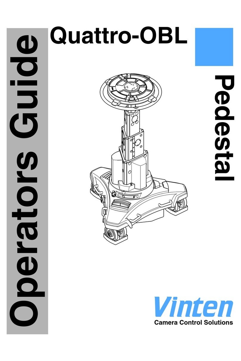
Vinten AutoCam SP-2000/X-Y Instruction Manual

i
SP-2000/X-Y
AutoCam™ Pedestal
Operation, Installation
And Maintenance
(pn AB-300101 for sn 80xxxx0020 - 021601)

ii
SP-2000/X-Y Pedestal
Safety
IMPORTANT!: Read the Safety Section starting on page 1-2
before installing or using this equipment, or attempting any
adjustment or repair. This safety triangle is used in the manual to
indicate important information. Read this information carefully to
avoid the risk of personal injury, injury to others, or damage to the equipment.
Warning Labels
Various colored safety labels are attached to the AutoCam equipment to alert you to
hazardous situations. The labels and their meaning are described below.
DANGER (with a red background) indicates an imminently
hazardous situation which, if not avoided, will result in death or serious injury.
WARNING (with an orange background) indicates a poten-
tially hazardous situation which, if not avoided, could result in death or serious
injury.
CAUTION (with a yellow background) indicates a potentially
hazardous situation which, if not avoided, may result in minor or moderate
injury.
CAUTION (with a yellow background, but without the Safety
Alert symbol) indicates a potentially hazardous situation which, if not avoided,
may result in property damage.

iii
Critical Data For SP-2000/X-Y
* NOTE: In a typical system, the AC power consumption of the pedestal, head and
rack mount power supply combined is 1000W maximum.
Mass (Weight) 525 lb (239 kg)
Maximum Load 320 lb (145 kg)
Maximum Pressure 150 bar (2200 psi)
Input Voltage +36 VDC nominal
Input Power* +4 Amps nominal
+12 Amps peak
Date Of Manufacture 2001

iv
Technical Support
If you are based in North, South or Central America and need technical support on
the AutoCam system, contact Vinten Inc. at:
709 Executive Blvd.
Valley Cottage, NY 10989
USA
Phone:1-888 4 VINTEN (1-888-484-6836) - Toll free in the U.S.A.
+1 845-268-0100
Fax:+1 845-268-0113
Or, if you are based outside of North, South or Central America, contact Vinten
Broadcast Limited at:
Western Way
Bury St. Edmunds
Suffolk IP33 3TB
ENGLAND
Phone: +44 (0) 284 752121
Fax: +44 (0) 284 750560

v
Warranty
Vinten, Incorporated (Vinten) warrants that its equipment shall be free of defects in
material and workmanship for a period of twelve (12) months from the first date of
installation, but no more than eighteen (18) months from date of shipment, and is
extended only to the original purchaser. Vinten, at its option, will repair or replace
defective components. Warranty covers only those defects that occur when the equip-
ment is used in the manner described in the Operation, Installation, and Service man-
ual. Vinten’s liability is limited to parts, material, and labor necessary to repair or
replace equipment manufactured by Vinten. Any and all consequential damages are
excluded. Consumable supplies and normal wear items are the customer’s responsi-
bility and are not covered by this warranty.
The warranty is in effect only when equipment is operated, adjusted, and maintained
in the manner described in the appropriate Operation, Installation, and Service man-
ual. Modifications, service by non-authorized service personnel, failure to provide
proper maintenance, and abuse and misuse of the equipment will void the warranty.
Repairs not covered by this warranty will be billed for parts, labor, and expenses at
the rates in effect at the time of service.
Warranty service and repair will normally be performed at the Vinten factory in Val-
ley Cottage, New York, but may, at the discretion of Vinten, be performed on the cus-
tomer site. It is the customer’s responsibility to contact Vinten and obtain
authorization prior to returning equipment for warranty service. Returned equipment
must include a Return Material Authorization (RMA) number, and a failure report
describing the nature of the failure or complaint as well as the customer’s name,
address, and a contact name and phone number.

vi
Copyright
The Vinten Inc. AutoCam User Manual is copyrighted with all rights reserved. Under
the copyright law, this manual may not be copied, in whole or in part, without written
consent from Vinten Inc.
© 1995 - 2001 by Vinten Inc.
Disclosure Statement - AutoCam System
This document contains information proprietary to Vinten Inc. Except by written
authorization from Vinten Inc., the information contained in this document shall not,
in whole or in part, be disclosed to third parties, reproduced for any purpose, or used
except for evaluation, operation and maintenance of equipment supplied by Vinten
Inc. or Vinten Broadcast.
Manual Outline
This manual covers the installation, operation and maintenance of the AutoCam SP-
2000/X-Y robotic pedestal. See Chapter 1 for a detailed description of the contents of
this manual.
Product Serial Numbers
Vinten AutoCam products are marked with unique serial numbers that include a 2
digit product identifier, a 4 digit serial number and a 2 character revision code. The
format is AABBBBXXCD where:
This manual is applicable to products that have serial numbers 80xxxx0020 where
xxxx may be any 4 digit number.
AutoCamTM, Vinten Inc.TM and Lubricated Friction (LFTM) are trademarks of
Vinten Inc. or Vinten Broadcast Limited.
Specifications and features are subject to change without prior notice.
(021601)
AA Product Identifier - 80 for the SP-2000/X-Y
BBBB Serial number
XX Reserved for future use - currently 00
C Primary revision status - 0, 1, 2, 3 etc.
D Secondary revision status - 0, A, B, C etc.

Table Of Contents
vii
SP-2000/X-Y Pedestal . . . . . . . . . . . . . . . . . . . . . . . . . . . . . . . . . . . ii
Safety . . . . . . . . . . . . . . . . . . . . . . . . . . . . . . . . . . . . . . . . . . . . . . . . ii
Warning Labels . . . . . . . . . . . . . . . . . . . . . . . . . . . . . . . . . . . . . . . . . . . . .ii
Critical Data For SP-2000/X-Y . . . . . . . . . . . . . . . . . . . . . . . . . . . . . . . . . iii
Technical Support . . . . . . . . . . . . . . . . . . . . . . . . . . . . . . . . . . . . . iv
Warranty . . . . . . . . . . . . . . . . . . . . . . . . . . . . . . . . . . . . . . . . . . . . . v
Copyright . . . . . . . . . . . . . . . . . . . . . . . . . . . . . . . . . . . . . . . . . . . . . . . . . vi
Disclosure Statement - AutoCam System . . . . . . . . . . . . . . . . . . . . . . vi
Manual Outline . . . . . . . . . . . . . . . . . . . . . . . . . . . . . . . . . . . . . . . . . . . . vi
Product Serial Numbers . . . . . . . . . . . . . . . . . . . . . . . . . . . . . . . . . . . . . vi
1Safety & Introduction
Safety Issues . . . . . . . . . . . . . . . . . . . . . . . . . . . . . . . . . . . . . . . . 1–2
Pedestal E-STOP Switches . . . . . . . . . . . . . . . . . . . . . . . . . . . . . . . . . 1–2
Other E-StOP Switches . . . . . . . . . . . . . . . . . . . . . . . . . . . . . . . . . . . . 1–3
Other Important Information . . . . . . . . . . . . . . . . . . . . . . . . . . . . . . . 1–5
Customer Responsibility . . . . . . . . . . . . . . . . . . . . . . . . . . . . . . . . . . . 1–5
Safe Working Environment . . . . . . . . . . . . . . . . . . . . . . . . . . . . . . . . . 1–5
Safe Operating Zone And Pedestal Footprint . . . . . . . . . . . . . . . . . 1–6
Pedestal Active Lights . . . . . . . . . . . . . . . . . . . . . . . . . . . . . . . . . . . . 1–6
Warning Signs . . . . . . . . . . . . . . . . . . . . . . . . . . . . . . . . . . . . . . . . . . . 1–7
Pedestals And Heads Can Start Unexpectedly . . . . . . . . . . . . . . . 1–7
Collision Bumper And Bumper Override . . . . . . . . . . . . . . . . . . . . . 1–8
Bumper Override 1–8
Pinch Points . . . . . . . . . . . . . . . . . . . . . . . . . . . . . . . . . . . . . . . . . . . . . 1–9
Sharp Edges . . . . . . . . . . . . . . . . . . . . . . . . . . . . . . . . . . . . . . . . . . . . . 1–9
Manual Outline . . . . . . . . . . . . . . . . . . . . . . . . . . . . . . . . . . . . . 1–10
The SP-2000/X-Y Servo Pedestal . . . . . . . . . . . . . . . . . . . . . . . 1–12
AutoCam Philosophy . . . . . . . . . . . . . . . . . . . . . . . . . . . . . . . . 1–14
Seamless Integration Into The Studio . . . . . . . . . . . . . . . . . . . . . . . 1–14
“Like Being Behind A Camera” . . . . . . . . . . . . . . . . . . . . . . . . . . . . 1–14
An Easy Transition . . . . . . . . . . . . . . . . . . . . . . . . . . . . . . . . . . . . . . . 1–15
Typical Applications . . . . . . . . . . . . . . . . . . . . . . . . . . . . . . . . . 1–16
ACP-8000P System . . . . . . . . . . . . . . . . . . . . . . . . . . . . . . . . . . . . . . 1–16
Typical System Configuration . . . . . . . . . . . . . . . . . . . . . . . . . 1–17
2Operation
Introduction . . . . . . . . . . . . . . . . . . . . . . . . . . . . . . . . . . . . . . . . . 2–2
Orientation . . . . . . . . . . . . . . . . . . . . . . . . . . . . . . . . . . . . . . . . . . 2–3

Table Of Contents
viii
Powering Up The SP-2000/X-Y . . . . . . . . . . . . . . . . . . . . . . . . . . 2–4
Powering Down . . . . . . . . . . . . . . . . . . . . . . . . . . . . . . . . . . . . . . . . . . 2–5
Standby/Charge 2–5
Stop 2–5
Emergency STOP Switches . . . . . . . . . . . . . . . . . . . . . . . . . . . . . 2–6
Direction Indicators . . . . . . . . . . . . . . . . . . . . . . . . . . . . . . . . . . 2–8
Pedestal Active Lights . . . . . . . . . . . . . . . . . . . . . . . . . . . . . . . . 2–9
Using The MCB Controller . . . . . . . . . . . . . . . . . . . . . . . . . . . . . 2–10
Local/Remote . . . . . . . . . . . . . . . . . . . . . . . . . . . . . . . . . . . . . . . . . . 2–10
Drive . . . . . . . . . . . . . . . . . . . . . . . . . . . . . . . . . . . . . . . . . . . . . . . . . . 2–10
Rotate . . . . . . . . . . . . . . . . . . . . . . . . . . . . . . . . . . . . . . . . . . . . . . . . 2–10
Raising/Lowering The Column . . . . . . . . . . . . . . . . . . . . . . . . . . . . . 2–10
Targeting . . . . . . . . . . . . . . . . . . . . . . . . . . . . . . . . . . . . . . . . . . 2–11
3Installation
Introduction . . . . . . . . . . . . . . . . . . . . . . . . . . . . . . . . . . . . . . . . . 3–2
Tools You Will Need . . . . . . . . . . . . . . . . . . . . . . . . . . . . . . . . . . . . . . 3–2
Floor Preparation For Robotic Pedestals . . . . . . . . . . . . . . . . . . 3–3
Removing The SP-2000/X-Y From Its Crate . . . . . . . . . . . . . . . . 3–4
Uncrating The Pedestal . . . . . . . . . . . . . . . . . . . . . . . . . . . . . . . . . . . 3–4
Unloading The Pedestal . . . . . . . . . . . . . . . . . . . . . . . . . . . . . . . . . . . 3–6
AC Powered Unloading . . . . . . . . . . . . . . . . . . . . . . . . . . . . . . . . . . . 3–8
Mounting The Pan/Tilt Head & Payload . . . . . . . . . . . . . . . . . 3–10
MCB Controller Mounting . . . . . . . . . . . . . . . . . . . . . . . . . . . . . . . . 3–11
Pressurizing And Balancing The Pedestal . . . . . . . . . . . . . . . . 3–12
Pressurizing The Pedestal . . . . . . . . . . . . . . . . . . . . . . . . . . . . . . . . . 3–12
Balancing The Pedestal . . . . . . . . . . . . . . . . . . . . . . . . . . . . . . . . . . 3–14
Finishing Up . . . . . . . . . . . . . . . . . . . . . . . . . . . . . . . . . . . . . . . . . . . . 3–15
Discharging The Pedestal . . . . . . . . . . . . . . . . . . . . . . . . . . . . . . . . 3–15
Calibrating The Collision Bumpers . . . . . . . . . . . . . . . . . . . . . 3–16
Electrical Installation And Interconnection . . . . . . . . . . . . . . 3–18
Removing The Payload . . . . . . . . . . . . . . . . . . . . . . . . . . . . . . 3–22
Recrating The Pedestal . . . . . . . . . . . . . . . . . . . . . . . . . . . . . . . 3–24
Crating The Pedestal . . . . . . . . . . . . . . . . . . . . . . . . . . . . . . . . . . . . 3–25
4Maintenance And Repair
Safety . . . . . . . . . . . . . . . . . . . . . . . . . . . . . . . . . . . . . . . . . . . . . . 4–2
Other Important Information . . . . . . . . . . . . . . . . . . . . . . . . . . . . . . . 4–3

Table Of Contents
ix
Customer Responsibility . . . . . . . . . . . . . . . . . . . . . . . . . . . . . . . . . . . 4–3
Pedestals And Heads Can Start Unexpectedly . . . . . . . . . . . . . . . 4–3
Pinch Points . . . . . . . . . . . . . . . . . . . . . . . . . . . . . . . . . . . . . . . . . . . . . 4–4
Sharp Edges . . . . . . . . . . . . . . . . . . . . . . . . . . . . . . . . . . . . . . . . . . . . . 4–4
Routine Maintenance . . . . . . . . . . . . . . . . . . . . . . . . . . . . . . . . . 4–6
Cleaning The Targets . . . . . . . . . . . . . . . . . . . . . . . . . . . . . . . . . . . . . 4–6
Removing Targets 4–6
DC Power . . . . . . . . . . . . . . . . . . . . . . . . . . . . . . . . . . . . . . . . . . . . . . . 4–7
Column Balance . . . . . . . . . . . . . . . . . . . . . . . . . . . . . . . . . . . . . . . . . 4–7
Overall Operation . . . . . . . . . . . . . . . . . . . . . . . . . . . . . . . . . . . . . . . . 4–7
E-STOP Switch Operation . . . . . . . . . . . . . . . . . . . . . . . . . . . . . . . . . . 4–8
Collision Bumper Operation . . . . . . . . . . . . . . . . . . . . . . . . . . . . . . . 4–8
Removing The Covers . . . . . . . . . . . . . . . . . . . . . . . . . . . . . . . . . . . . 4–9
The North Cover 4–9
The West Wheel Cover 4–10
The East Wheel Cover 4–11
Replacing The Covers 4–12
Cleaning The Target Sensors . . . . . . . . . . . . . . . . . . . . . . . . . . . . . . 4–14
Cleaning The Slip Rings . . . . . . . . . . . . . . . . . . . . . . . . . . . . . . . . . . 4–16
Examining The Wheels . . . . . . . . . . . . . . . . . . . . . . . . . . . . . . . . . . . 4–18
Cylinder Replacement . . . . . . . . . . . . . . . . . . . . . . . . . . . . . . . 4–20
Electronics Repair . . . . . . . . . . . . . . . . . . . . . . . . . . . . . . . . . . . 4–22
Service Philosophy . . . . . . . . . . . . . . . . . . . . . . . . . . . . . . . . . . . . . . 4–22
Safety . . . . . . . . . . . . . . . . . . . . . . . . . . . . . . . . . . . . . . . . . . . . . . . . . 4–22
Calibration . . . . . . . . . . . . . . . . . . . . . . . . . . . . . . . . . . . . . . . . . 4–24
Collision Bumpers . . . . . . . . . . . . . . . . . . . . . . . . . . . . . . . . . . . . . . . 4–24
Target Sensor Calibration . . . . . . . . . . . . . . . . . . . . . . . . . . . . . . . . 4–26
Theory Of Operation . . . . . . . . . . . . . . . . . . . . . . . . . . . . . . . . . 4–30
System . . . . . . . . . . . . . . . . . . . . . . . . . . . . . . . . . . . . . . . . . . . . . . . . 4–30
Power Bus . . . . . . . . . . . . . . . . . . . . . . . . . . . . . . . . . . . . . . . . . . . . . . 4–30
Data Bus . . . . . . . . . . . . . . . . . . . . . . . . . . . . . . . . . . . . . . . . . . . . . . . 4–30
Battery Pack and Power Management . . . . . . . . . . . . . . . . . . . . . 4–31
Battery Bypass 4–32
The Targeting System . . . . . . . . . . . . . . . . . . . . . . . . . . . . . . . . 4–34
Lowering The Sensors . . . . . . . . . . . . . . . . . . . . . . . . . . . . . . . . . . . . 4–34
The Sensor Assembly . . . . . . . . . . . . . . . . . . . . . . . . . . . . . . . . . . . . . 4–34
The Dolly Board . . . . . . . . . . . . . . . . . . . . . . . . . . . . . . . . . . . . . . . . . 4–34
4-Channel Servo Boards . . . . . . . . . . . . . . . . . . . . . . . . . . . . . . . . . 4–35
Analog 4–35
Digital 4–35
Brushless Motors . . . . . . . . . . . . . . . . . . . . . . . . . . . . . . . . . . . . . . . . . 4–36
Motor Drive Amplifiers . . . . . . . . . . . . . . . . . . . . . . . . . . . . . . . . . . . 4–36

Table Of Contents
x
This page left blank intentionally.

User Manual 1-1
1Safety & Introduction

SP-2000/X-Y Safety & Introduction
1-2 User Manual
Safety Issues
Safety issues including important warnings, risks and related topics are covered
in this section of the manual. It is very important that this information be avail-
able to all personnel who will work on or near the Autocam equipment.
Pedestal E-STOP Switches
3 EMERGENCY STOP switches are located on the top of
each pedestal base. Make sure that all personnel are aware of
the location and operation of these pedestal E-STOP switches
and the main pedestal power down switch before operating
the equipment.Press down firmly on any one of the E-STOP switches to
immediately disable the pedestal and head.
The Off Switch can also be used, but only if the operator can press it quicker that
than one of the E-STOP switches.
After clearing the cause for the emergency stop, twist the appropriate E-STOP
switch clockwise to release it. The pedestal and head can now be powered up
and targeted - see Chapter 2 for operating procedures.
Emergency STOP Switches
(1 hidden)
Pedestal Off Switch

SP-2000/X-Y Safety & Introduction
User Manual 1-3
Other E-StOP Switches
An E-Stop switch for each pedestal (of the type shown below) is installed at
each operator location and optionally at other locations.
Make sure that all personnel are aware of the location and
operation of these E-STOP switches before operating the
equipment. Press down firmly on the E-STOP switch to imme-
diately disable the associated pedestal and head.
After clearing the cause for the emergency stop, pull up the appropriate E-STOP
switch. The pedestal and head can now be powered up and targeted - see Chap-
ter 2 for operating procedures.

SP-2000/X-Y Safety & Introduction
1-4 User Manual
WARNING! - Always set the column to minimum height, turn
power off and engage the two locking pins in the base of the
column before removing the camera or other payload equip-
ment from the head. Or, discharge the gas from the pedestal.
WARNING - NEVER work directly under the camera if the
column is raised. In the unlikely event that the gas pressure
supporting the column is lost, the head and payload may drop
quickly.
CAUTION - NEVER stand under the payload when you
power up the pedestal or switching from Local to Remote on
the MCB Controller. The column may change height quickly.
CAUTION - NEVER attach cables to the head or camera
which could pull the pedestal over if it is moved with the col-
umn extended.
Locking Pin Installed

SP-2000/X-Y Safety & Introduction
User Manual 1-5
CAUTION - Depending on your choice of equipment, the pay-
load in your application may be over 300 lb (over 136 kg).
Therefore, to avoid personal injury, or injury to others, we
recommend that each element of the payload (teleprompter,
lens, camera etc.) be removed separately. ALWAYS follow the handling
instructions supplied by the manufacturers of the payload equipment.
Make sure that you have enough people involved to safely handle the weight
of your payload equipment.
Other Important Information
1. To avoid personal injury, always exercise caution when working in the
vicinity of energized pedestals as they can start to move without any warn-
ing.
2. TUnless it is impossible, you should always de-energize the pedestal and
head before working on any part of the pedestal, the head, the camera/lens,
or any associated equipment.
Customer Responsibility
It is the customer’s responsibility to ensure that the workplace is safe. Make sure
that you comply with local safety requirements for owning and operating robotic
equipment. In normal operation, the remote controlled pedestals, heads and pay-
loads in an Autocam system can move suddenly and without warning. Since
audible warnings are out of the question in normal television applications, it is
recommended that only trained personnel be allowed to work in the active areas
where the remote controlled pedestals, heads and payloads are located. As part
of the training, personnel must be made aware of the hazards of working in a
robot environment, including the specific hazards listed below. The forces are
sufficient to cause personal injury, or injury to others and therefore, caution is
essential.
Safe Working Environment
Each of the remote controlled pedestals should be within the view of the opera-
tor of the Autocam system at the controller. Before and during remote operation,
the controller operator must verify visually that the active area is clear. If per-
sonnel are too close to one of the pedestals that is about to move, the operator
can prevent the motion from starting, or stop the motion after it has started.
If the direct line of sight is obstructed in your installation, it is recommended
that one or more viewing cameras are installed to cover the active areas and
allow the operator to view the entire workspace at all times.

SP-2000/X-Y Safety & Introduction
1-6 User Manual
Safe Operating Zone And Pedestal Footprint
The safe operating zone for personnel is a minimum of 3 feet (1m) outside of the
pedestal footprint. This allows time for the personnel to avoid a pedestal that
starts to move at its maximum speed of approximately 1 foot per second (0.3m
per second).
The pedestal footprint is typically larger than the pedestal base itself. In most
installations, the teleprompter is the piece of equipment mounted on the head
that protrudes the furthest beyond the base of the pedestal. Or, it may be the
manual control bars on the rear that protrude the furthest. The footprint must
take into account the overhang of the teleprompter and/or manual control bars as
the head pans around.
If your operating practices require personnel to work less than 3 feet (1m) out-
side the pedestal footprint, you must make sure that they are trained and are
aware of the hazards of working in a robot environment, including the specific
hazards listed below. The forces are sufficient to cause personal injury, or injury
to others and therefore, caution is essential.
Pedestal Active Lights
At each corner of the base of the pedestal, a pair of lights will flash to indicate
that the pedestal is in motion, or may move at any time without additional warn-
ing. These lights are activated by Locate mode at the controller and do not oper-
ate if the pedestal is being controlled locally by the MCB controller.
Pedestal In Motion Lights
(2 East, 2 West, 2 North)

SP-2000/X-Y Safety & Introduction
User Manual 1-7
Warning Signs
Warning signs should be displayed prominently in the workplace as a reminder
to trained personnel, and a primary warning to untrained personnel and visitors.
A typical sign might read:
WARNING:
Robotic Pedestals, Heads And Lenses
Move Suddenly Without Warning
Pedestals And Heads Can Start Unexpectedly
The hazards associated with robotic camera systems are only slightly different
than those associated with operating a camera under conventional manual con-
trol. The speeds and camera weights are similar. The main difference is that with
automation, the operator is normally not near the cameras, and it is more diffi-
cult to verify that the area is clear. For personnel working on or near the pedes-
tals, they must be aware that the equipment can start moving unexpectedly.
All personnel should be trained and aware of the hazards of robotic pedestals
and heads, and the fact that they can move at any time. They must be trained on
how far the pedestals, heads and payloads can move, the speeds involved, and
the need to stay back an appropriate distance.
Most adjustments to the camera and head, such as balancing and camera calibra-
tion, should be made with the system de-energized. However, if adjustments are
absolutely necessary while the pedestal and/or head is powered, they should
only be made by trained technical personnel familiar with the AutoCam robotics
system. They must understand that the pedestal or head can move unexpectedly
at any time, and they must position themselves so that any motion would not
cause them personal harm.
When the robotic heads move, the speeds involved are fairly slow. However, the
equipment is still capable of generating sufficient force to cause injury. There-
fore, it essential that you exercise caution. In particular, be aware that the tele-
prompter is usually the fastest swinging element.
Any failure of the system could possibly cause one or more axes to move on
their own, but the speeds and forces should not be noticeably greater than those
encountered during normal use.

SP-2000/X-Y Safety & Introduction
1-8 User Manual
Collision Bumper And Bumper Override
The skirts around the base of the pedestal contain a collision detection bumper
that automatically stops the pedestal if it collides with an obstacle. The bumper
as shown below is electro-optical and is an integral part of the cable skirt..
The electro-optical bumper system does require calibration - see Chapter 4
When a collision occurs, the sequence of events is:
1. The pedestal involved in the collision stops immediately. Pan, tilt, zoom,
focus and pedestal height are still active, so operation can still continue
using a stationary pedestal.
2. An error message (“dolly “n”stopped, bumper contact”) appears on the
controller touchscreen where “n”is the number of the pedestal that tripped
its bumper. A “B”appears in the column of the pedestal that has tripped its
bumper circuit. Touch anywhere on the screen to clear the error message
and continue operation.
3. As soon as is practical, check the work area to clear the obstacle that
caused the collision and use LOCATE mode (see Controller User Manual)
to back the pedestal away. Be aware that the other pedestals in the studio
are still active and can move at any time.The “B”will disappear indicating
that the bumper circuit is reset. Normal operation can now continue.
Bumper Override
In the unlikely event that a pedestal stops due a failure in the collision detection
system, or the bumper does not reset after a collision, it is still possible to con-
tinue operating in an emergency. In this situation, the “B”on the screen will not
disappear when you back away from the obstacle but you can still operate the
pedestal.
Collision Bumper
Loosen To Adjust
Skirt Height

SP-2000/X-Y Safety & Introduction
User Manual 1-9
HOWEVER, THIS IS FOR EMERGENCY OPERATION ONLY
BECAUSE THE BUMPERS ARE NO LONGER ACTIVE AND WILL
NOT STOP THE PEDESTAL IF THERE IS ANOTHER COLLISION. IT
IS NOT SAFE TO OPERATE THE PEDESTAL WITHOUT COLLISION
BUMPER PROTECTION.
As soon as possible, check the collision bumper system and circuit calibration
(electro-optical bumper type only - see Chapter 4) to determine the cause of the
failure and take corrective action.
Pinch Points
Particular care should be exercised around possible points where you could get
pinched, such as the tilt cradle. Here, the forces can be somewhat greater, due to
the short lever arm.
Sharp Edges
If the lens, teleprompter or other camera attachments have sharp edges that
could cause injury, make sure they are padded or protected.

SP-2000/X-Y Safety & Introduction
1-10 User Manual
Manual Outline
Chapter 1 This chapter covers important safety issues
and gives an overview of the SP-2000/X-Y
pedestal and the AutoCam system.
Chapter 2 Step by step instructions for operating the SP-
2000/X-Y pedestal.
Chapter 3 Step by step instructions for unpacking and
installing the SP-2000/X-Y pedestal.
Chapter 4 Technical information including routine
maintenance, circuit descriptions, calibra-
tion, schematics and parts lists.
Table of contents
Other Vinten Camera Accessories manuals

Vinten
Vinten Vector 700 User manual

Vinten
Vinten Vision 3AS Manual

Vinten
Vinten Quattro SL User manual

Vinten
Vinten flowtech 75 User manual

Vinten
Vinten Vector 700H Manual

Vinten
Vinten FH-145 User manual

Vinten
Vinten OB Quattro Manual

Vinten
Vinten Vision 30 User manual

Vinten
Vinten Vector 75 V4095-0001 Manual

Vinten
Vinten Vision 6 Manual

Vinten
Vinten Fulmar Pedestal User manual

Vinten
Vinten Osprey Plus Manual

Vinten
Vinten V4045-4980 Manual

Vinten
Vinten Vector 750i User manual

Vinten
Vinten Vision 11 Manual

Vinten
Vinten Protouch PRO-6 HDV Manual

Vinten
Vinten Vision 100 Manual

Vinten
Vinten FE-165 Light User manual

Vinten
Vinten vector 750 Manual

Vinten
Vinten Vision 11 User manual