Vinten V4165-0002 User manual

User Guide
www.vinten.com
EN
Environmental Camera Enclosure
Weatherproof camera enclosure
Weatherproof camera enclosure, fan cooled
Weatherproof camera enclosure with AC cooler

Copyright © 2020
All rights reserved.
Original Instructions: English
All rights reserved throughout the world. No part of this publication may be stored in a retrieval system, transmitted, copied or reproduced in any
way, including, but not limited to, photocopy, photograph, magnetic or other record without the prior agreement and permission in writing of the
Videndum Plc.
Disclaimer
The information contained in this publication is believed to be correct at the time of printing. Videndum Production Solutions Ltd reserves the right
to make changes to the information or specifications without obligation to notify any person of such revision or changes. Changes will be
incorporated in new versions of the publication.
We are making every effort to ensure that our publications are updated on a regular basis to reflect changes to product specifications and features.
Should this publication not contain information on the core functionality of your product, please let us know. You may be able to access the latest
revision of this publication from our website.
Videndum Production Solutions Ltd reserves the right to make changes to product design and functionality without notification.
Trademarks
All product trademarks and registered trademarks are the property of The Videndum Plc.
All other trademarks and registered trademarks are the property of their respective companies.
Published by:
Videndum Production Solutions Ltd
Supports Technical Publications Department
Email: technical.publications@videndum.com

Contents
Safety and Warnings ........................ 2
Warning symbols used in these instructions ..... 2
Health and Safety ......................... 3
Intended Use .............................5
Operating Description ...................... 5
Safe Operating Zone ....................... 5
Safety Notes for Operators .................. 5
Models ....................................6
Weatherproof camera enclosure.............. 6
Weatherproof camera enclosure, fan cooled..... 6
Weatherproof camera enclosure with AC cooler .. 6
External Components ....................... 7
Installation.................................8
Mounting Enclosure to Cradle ................ 8
Mounting Camera & Skid Plate ............... 9
Longer Lenses . . . . . . . . . . . . . . . . . . . . . . . . . 9
Shorter lenses: ....................... 10
Cable Entry Box: ...................... 11
Lid Closure and Sealing: ................ 12
Cooler Use: .......................... 13
Optional Fan speed control: ............. 14
Water pump for Wiper: ................. 14
Electrical Connections .................. 15
Cable Management ....................... 15
Maintenance .............................. 16
Regular Checks.......................... 16
Routine Use.............................16
Cleaning ...............................16
Changing the Fuse ....................... 16
Troubleshooting .......................... 17
Specications ............................. 18
Compliance ...............................19
Declaration of Conformity .................. 19

2
Safety and Warnings
Important information on the safe installation and operation of
the product. Read this information before operating the product.
For your personal safety, read these instructions. Do not operate
the product if you do not understand how to use it safely. Save
these instructions for future reference.
Warning symbols used in these instructions
Safety cautions are used in these instructions. These safety
instructions must be followed to avoid possible personal injury and
possible damage to the product.
!
WARNING! Where there is a risk of personal injury or
injury to others, comments appear supported by the
warning triangle symbol.
Where there is a risk of damage to the product, associated
equipment, process or surroundings, comments appear
supported by the word ‘CAUTION!’.
ELECTRIC SHOCK Where there is a risk of electric shock,
comments appear supported by the hazardous voltage
warning triangle.
WARNING! Unexpected movement may occur.
Risk of trapped hand / ngers.
TM
CAUTION! Please refer to the user guide for further
information
CAUTION! Maximum camera weight
This label V4165-2070 is to be xed securely to side of the enclosure.
TM
CAUTION! Please refer to the user guide for further
information
WARNING! Maximum camera weight
IP65 This product is protected from dust and water ingress to
IP65 under the following conditions listed in the manual.
100-
240VAC,
3A,
50-60Hz
Electrical supply to be protected by RCD 30mA,
40ms. Do not open the lid in wet conditions. Follow
all the instructions in this manual. Use wiring suitably
protected from UV rays. Route and protect wiring from
abrasion due to robotic movement or movement in the wind.
EN: The device must be connected to a grounded outlet.
DNK: Apparatets stikprop skal tilsluttes en stikkontakt med
jord som giver forbindelse til stikproppens jord
FIN: Laite en liitettävä suojakoskettimilla varustettuun
pistorasiaan
NOR: Apparatet må tilkoples jordet stikkontakt
SWE: Apparaten skall anslutas tilljordat uttag
Symbols on this Warning Label.

3
Safety and Warnings
Health and Safety
!
WARNING! Risk of personal injury or injury to
others. All personnel must be fully trained and adhere to
correct manual handling techniques and Health & Safety
regulations. It is the responsibility of the local organisation
to enforce safe working practices at all times.
!
WARNING! Follow all warnings and instructions marked
on the product and in this manual. Safety warnings are
included in this manual. These safety instructions must be
followed to avoid possible personal injury and damage to
the product.
!
WARNING! Do not install this product onto a bracket,
support or other equipment that is not designed to support
the weight of the product and its payload. All supports
must comply with local government regulations.
!
WARNING! The tting of non-approved parts and
accessories, or the carrying out of non-approved
alterations or servicing can be dangerous and could aect
the safety of the product. It may also invalidate the terms
and conditions of the product warranty.
!
WARNING! Risk of personal injury or injury to others. All
personnel must be fully trained and adhere to local health
and safety laws and guidelines. It is the responsibility of
the local organisation to enforce safe working practices at
all times.
!
CAUTION!
These products are designed for robotic use only and
are operated remotely. Do not attempt to operate these
products manually.
Electrical Connections
WARNING! This product must be connected to a power
supply of the same voltage (V) and current (A) as
indicated on the product and described in the Technical
Specications section of this manual. To reduce the risk of
electric shock, do not remove the covers.
No user serviceable parts inside. Refer all servicing to
qualied service personnel.
WARNING! Installation to use RCD protection device on
mains supply to BS7288 or equivalent, 30mA, 40ms.
WARNING! Inspect the AC cable regularly for signs of
wear or damage. If the AC cable is damaged, it must be
replaced.
!
CAUTION! Only use the power cable certied for the
country of use. 90-240V AC 50Hz (earthed) via cable, into
box with IEC termination to PSU
WARNING! This product is Class 1 equipment. For safe
operation this equipment must be connected to a power
supply that has a protective earth connection (US: ground).
Operating Environment
!
CAUTION! The product should not be used outside the
operating temperature limits. Refer to the product technical
specications for the operating limits for the product.

4
Safety and Warnings
Cleaning and Maintenance
!
CAUTION! Do not use solvent or oil-based cleaners,
abrasives or wire brushes to remove accumulations of
dirt as these damage the protective surfaces. To clean
mechanical surfaces, use only detergent-based cleaners
!
CAUTION! Do not use oil or grease on any exposed part
of the product. This is unnecessary and traps dirt which
acts as an abrasive
!
WARNING! The tilt lock MUST be engaged whenever
the head is lifted or transported and before installing or
adjusting the camera or payload. See head manual.
WARNING! Risk of electric shock. Always disconnect
and isolate the product from the power supply before
cleaning.
These are IP rated products. Any modication not
described in this manual could void IP rating warranty.
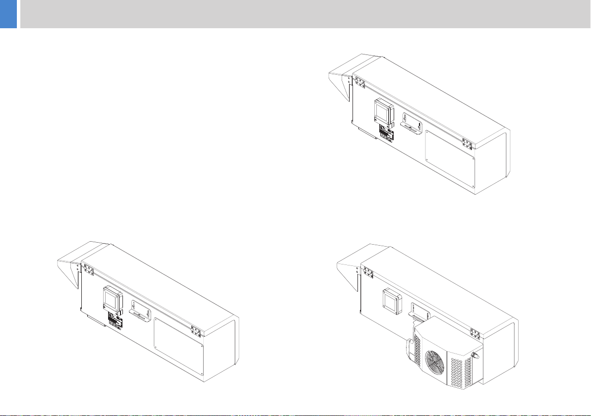
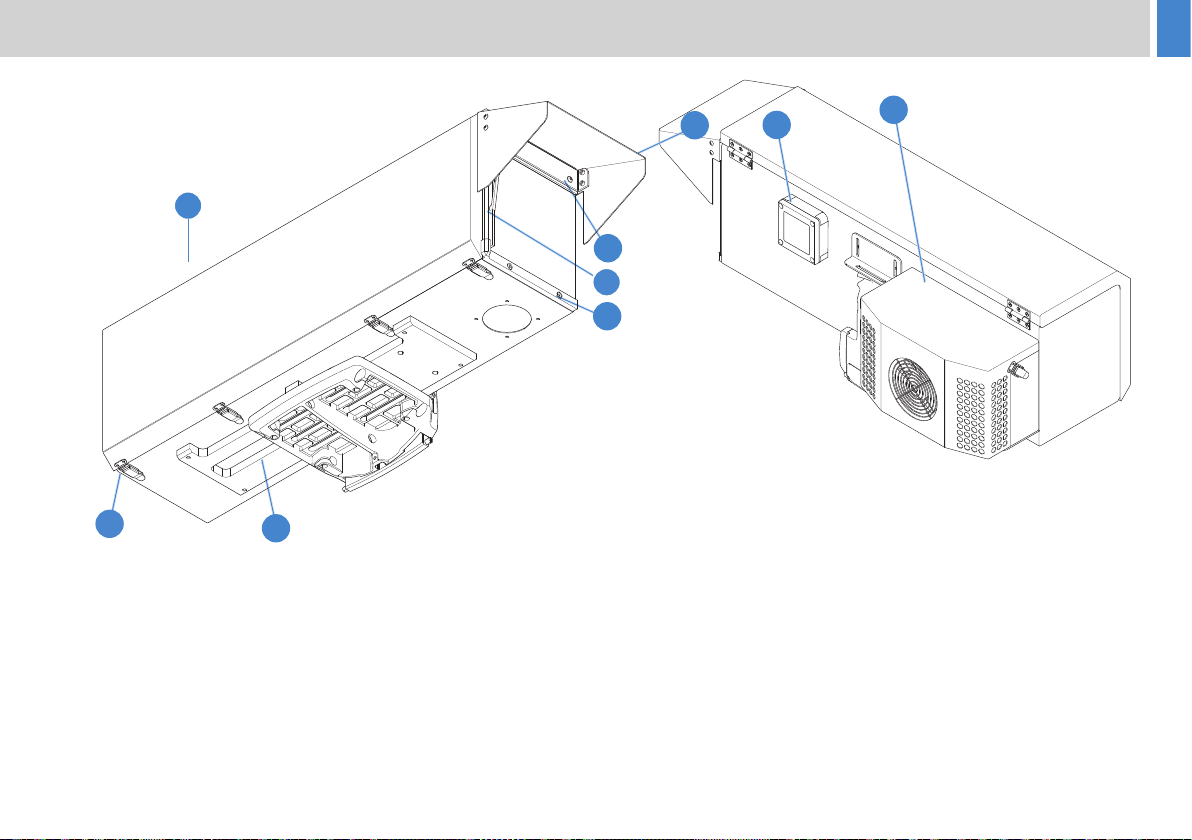
Mounting and Installation
!
WARNING! Always ensure that all power and auxiliary
communications cables are routed so that they do not
present any danger to personnel. Take care when routing
cables in areas where robotic equipment is in use.
!
CAUTION! Perform a risk assesment before mounting
or adjusting the enclosure. Where possible move or
adjust the enclosure with 2 people. Adjustments should
only be made by trained personnel.
!
CAUTION! Only install this equipment on a support
system rated for the load. Ensure support structures (such
as scaolding, cranes or building elements) are suciently
strong for the whole system and all weather conditions,
access for tting and maintenance is safe and secure.
!
CAUTION! Use the tilt lock provided when working on the
enclosure, and release it when leaving the site.
!
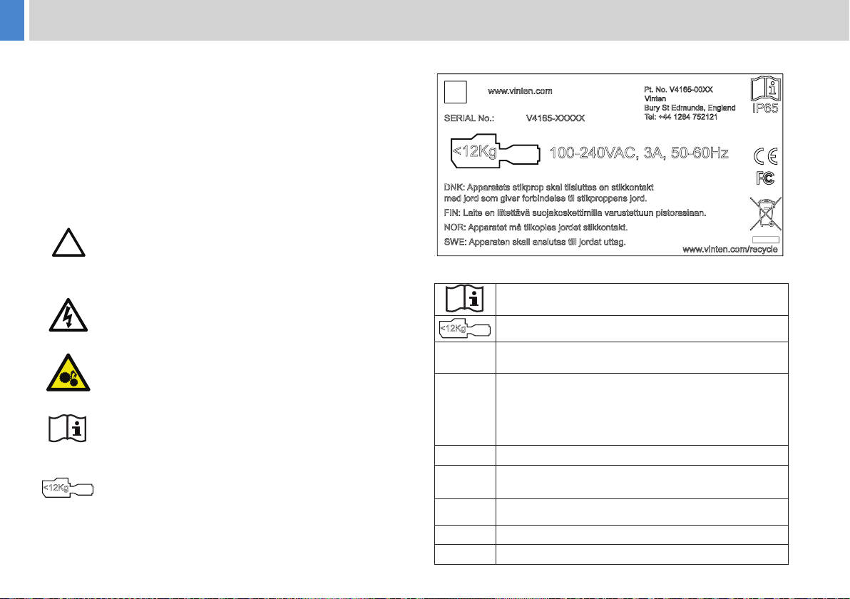
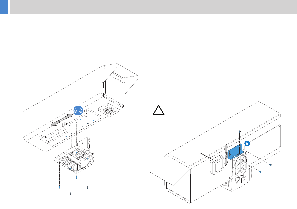
CAUTION! Enclosure Mass 23Kg, Enclosure Payload:
12Kg Maximum, Total mass with payload 35Kg.
!
CAUTION! The enclosure is only to be used with the
xing plate underneath the assembly (lid to the top), never
upside down.
WARNING! Open the lid fully so it rests on the top of the
cradle area and secure. If closed by the wind or by gravity
it may cause injury to ngers, be damaged, or cause the
user to fall.
!
CAUTION! The glass window is fragile. Avoid tapping the
edges of the glass with hard objects.
!
CAUTION! Tilt range from horizontal (horizon), glass
towards the ground 90˚, avoid pointing lens towards the
sky as much as possible. Do not direct the glass directly
towards the sun.
!
WARNING! When mounted at height it is recommended
that secondary protection against falling is installed, such
as a net below the product or securing cables. These
should be suitable of supporting the weight of the product
and its payload should the primarily mounting method fail.

5
Intended Use
This product is designed as a enclosure to protect a broadcast camera
and lens for outdoor use.
Operating Description
A sealed box with appropriate mechanical support and electronic
interfaces for typical broadcast quality camera and lens equipment.
Safe Working Environment
In normal operation, remote-controlled equipment can move
suddenly and without warning. It is recommended that only trained
personnel be allowed to work in the active areas, where
remote-controlled are located.
Personnel must be made aware of the potential hazards of working
in a robotic environment. To avoid personal injury, personnel should
always exercise caution when working in the vicinity of robotic
equipment. The forces are sucient to cause personal injury or injury
to others, and therefore caution is essential.
Safe Operating Zone
The safe operating zone for personnel is a minimum of 1 m (3
ft) outside of the footprint of the pan and tilt head and enclosure.
This should be extended to include potential fall areas for product
mounted at height.
Warning Signs
Warning signs should be displayed prominently in the workplace
alerting personnel that robotic equipment is in use and may move
suddenly and without warning.
If personnel are working on robotic or associated equipment, ensure
a warning sign is placed at the controller (control panel) to alert
operators that work is being carried out.
Safety Notes for Operators
Operators must familiarise themselves with the working footprint of
the robotic head and enclosure, to prevent inadvertent collisions or
injury to personnel.
If personnel are too close to a head that is about to move, the
operator should prevent the motion from starting or stop the motion if
it has started.
We strongly recommend that the operator veries visually that the
active area is clear of hazards and personnel, both before and during
remote operation.

6
Models
Weatherproof camera enclosure with AC cooler
Weatherproof camera enclosure
Weatherproof camera enclosure, fan cooled
Enclosures
The range of enclosures covers three models:
IP65 rated Weatherproof camera enclosure
IP63 rated Weatherproof camera enclosure, fan cooled
IP65 rated Weatherproof camera enclosure with AC cooler

7
External Components
3
2
56
7
8
1
1 . . . . . . . . . . . . . . . . . . . . . . . . . . . . . . . . . . . . . . . . . . Enclosure Lid
2 . . . . . . . . . . . . . . . . . . . . . . . . . . . . . . . . . . . . . . . . . . . . .Sun shade
3 . . . . . . . . . . . . . . . . . . . . . . . . . . . . . . . . . . . . . . . Glass top bracket
4 . . . . . . . . . . . . . . . . . . . . . . . . . . . . . . . . . . . . . . . . . . . . . . . . Wiper
5 . . . . . . . . . . . . . . . . . . . . . . . . . . . . . . . . . . . . Lid fastening catches
6 . . . . . . . . . . . . . . . . . . . . . . . . . . . . . . . . . . . . . . Cradle mount plate
7 . . . . . . . . . . . . . . . . . . . . . . . . . . . . . . . . . . . . . . lower glass bracket
8 . . . . . . . . . . . . . . . . . . . . . . . . . . . . . . . . . . . . . . . . .Cable entry box
9 . . . . . . . . . . . . . . . . . . . . . . . . . . . . . . . . . . . . . . . . . . . . Cooler unit
9
4

8
Installation
Mounting Enclosure to CradleMounting Enclosure to Cradle
With the cradle all-ready mounted to the head, attach the Enclosure toWith the cradle all-ready mounted to the head, attach the Enclosure to
the cradle as shown belowthe cradle as shown below
•• Estimate the balance point of the enclosure and using the mostEstimate the balance point of the enclosure and using the most
suitable mounting holes on the enclosure mounting plate, securesuitable mounting holes on the enclosure mounting plate, secure
with the 4 x hex screws.with the 4 x hex screws.
•• Refer to Head manual for balancing procedure.Refer to Head manual for balancing procedure.
•• Adjust the lock plate vertically on the rear of the enclosure toAdjust the lock plate vertically on the rear of the enclosure to
ensure a good t and tighten the hex screws.ensure a good t and tighten the hex screws.
•• This will add further stability to the enclosure.This will add further stability to the enclosure.
•• Overall balance adjustment is limited by the bracket highlightedOverall balance adjustment is limited by the bracket highlighted
in the picture below. With most camera and lens congurations in the picture below. With most camera and lens congurations
balance is possible with very little adjustment.balance is possible with very little adjustment.
•• With exceptional payloads trim weights should be used inside With exceptional payloads trim weights should be used inside
the enclosure. Trim weights should be secured to prevent themthe enclosure. Trim weights should be secured to prevent them
from shifting during operation.from shifting during operation.
•• Run the bre optic and all other cables into the enclosure Run the bre optic and all other cables into the enclosure
through the cable box before trying to t the camera. through the cable box before trying to t the camera.
Refer to ”Cable Entry Box:” on page 11Refer to ”Cable Entry Box:” on page 11
•• The cables should to be placed neatly along the back wall of theThe cables should to be placed neatly along the back wall of the
enclosure once the camera is tted.enclosure once the camera is tted.
Head removed for clarity
Cable Box
!
CAUTION! Fit the enclosure to support
equipment ensuring all bolts are tight before
installing the camera and lens.

9
Installation
Mounting Camera & Skid PlateMounting Camera & Skid Plate
The diagram below shows the skid plate and related xing points.The diagram below shows the skid plate and related xing points.
There are 2 wing nuts to the rear of the camera, and a clamp to theThere are 2 wing nuts to the rear of the camera, and a clamp to the
front. The skid sits against blocks to the back of the enclosure.front. The skid sits against blocks to the back of the enclosure.
The customer is to provide a suitable adaptor to go under their model
of camera, such as the Hitachi TA-Z3, or Sony VCT-14.
Test how the skid plate is secured into the enclosure before
tting the camera.
On some models hand grips and other large elements will
have to be removed from the camera
Plan ahead! There is a little adjustment allowed when
tting the assembled camera and skid into the enclosure,
however, the camera must be tted to appropriate slots.
Where will depend on the length of the lens. Long lenses,
with need of support, must use the support post provided
on the skid.
Attach the camera and lens assembly as shown belowAttach the camera and lens assembly as shown below
Longer Lenses
Larger lenses are supplied with a skid and support post for the lens
itself. This is to be replaced, where required by the arrangement shown
below. This dictates where the camera locates.
•• Slide the camera along the assembly plate until the lens mountingSlide the camera along the assembly plate until the lens mounting
point aligns with the lens mount on the plate.point aligns with the lens mount on the plate.
•• Adjust the lens mount vertically to suit the lens and secure allAdjust the lens mount vertically to suit the lens and secure all
xings.xings.
Skid Plate
Lens Mount
Fit the lens to the camera before placing the assembly back
into the enclosure.
Ensure settings are correct on areas of the camera that will
be obscured when tted into the enclosure, and any cables
are connected.
Connect the lens cables, and the Vinten data cable (Digital
only for Fujion or Cannon Lenses) ensuring that the lens is
set correctly for remote operation.

10
Installation
Shorter lenses:
Where a short lens is being tted, use slots in the skid plate to position
the camera forward in the enclosure. The PSU is to be moved to the
rear mounting location and cable tied to the metal strap provided. This
restores enclosure balance.
Loose insulation is provided to ll in gaps where possible
once the camera is tted.
Short lens cameras, move
the PSU here to restore
enclosure balance

11
InstallationInstallation
Cable Entry Box:
•• The cable entry box has provision for 4 cables: The cable entry box has provision for 4 cables:
•• A 240V IEC cable connection into the enclosure from the main A 240V IEC cable connection into the enclosure from the main
umbilical to the equipment.umbilical to the equipment.
•• A 240V IEC to weatherproof Neutric NAC connection to the A 240V IEC to weatherproof Neutric NAC connection to the
robotic head.robotic head.
•• Data cable from the robotic head into the enclosure.Data cable from the robotic head into the enclosure.
•• Optical & CCU camera connection cable from the camera control Optical & CCU camera connection cable from the camera control
unit (Max diameter 16mm). unit (Max diameter 16mm).
•• They enter the box via a water shedding clam shell arrangement. They enter the box via a water shedding clam shell arrangement.
In temporary site locations, with non-condensing day / nightIn temporary site locations, with non-condensing day / night
thermal cycling, this might oer adequate protection. However the thermal cycling, this might oer adequate protection. However the
following process is required to meet IP63 and 65 specications following process is required to meet IP63 and 65 specications
and is recommended for any xed installation. and is recommended for any xed installation.
•• Note! A 5th small cable may also be tted for the water bottle Note! A 5th small cable may also be tted for the water bottle
pump if tting, Make sure this is tted before sealing the entry box.pump if tting, Make sure this is tted before sealing the entry box.
1. Base of clamp will already be assembled into the outer box.
2. Apply DC4 compound (thick non setting silicone based grease) to
the clamping area and sealant to the void. The DC4 helps ll any
gaps when the neoprene foam is compressed.
3. Position cables and apply DC4 and Sealant. Apply DC4 between
cables to ensure it lls the voids between cables
DC4
Compound
DC4
Compound
Setting
Silicone
Setting
Silicone

12
Installation
4. Apply DC4 and Sealant to top clamp piece and attach to base
using screws.
Lid Closure and Sealing:
Avoid resting tools against lid seals.
Avoid closing lid with wires or other items in the shut line.
Inspect lid seal for contamination or damage before nal closure.
Ensure all items and internal surfaces are completely dry.
If atmospheric humidity is high (>50%) when tting equipment fresh
silicone gel sachets should be placed inside.
Note! Where gel sachets are added, it is recommended that they be
secured to prevent movement, a dab of strong adhesive or cable tied
to a secure point.
Humidity will not be able to escape, and if not absorbed by gel it will
condense on the inside of the glass window, within the lens or on
metal elements within equipment. This will be especially important in
locations with large day/night thermal cycles.
Ensure all 4 catches are secure after closing the lid.
In locations where the ambient temperature will fall below 5˚C avoid
turning o the equipment, or, install dedicated heating to prevent
internal temperatures falling below the dew point.
DC4
Compound
Setting
Silicone
Setting
Silicone
1. Finish by lling any gaps around the cables with sealant. Finally
screw on the lid of the outer box.

13
Installation
Cooler Use:
The cooler will maintain a temperature at least 10˚C below the
ambient air temperature outside under the following conditions:
Customer equipment should produce not more than 25W of heat.
Sun loading to DEF STAN-00-35, Desert A1, up to 1100W/m2.
The internal air temperature is measured at the handle of the camera
as shown in the image.
For example, when the ambient air temperature outside is 55˚C the
enclosure temperature at the thermostat will be cooled to 45˚C with
peak sun loading. This is the absolute maximum performance and
note that DEF STAN-00-35 limits peak ambient temperature to 47˚C.
It is recommended that the thermostat is set no lower than 35˚C.
Running the cooler in low temperature conditions will promote
condensation on the cooling plates and will operate the fans
unnecessarily.
The following graph shows how much energy in Watts the cooler can
remove from the enclosure with increasing temperature dierence
inside to outside (Δt).
WARNING! If power is lost to the enclosure the cooler will stop.
A camera and lens, when supplied by the bre optic, will continue to
generate heat and internal temperature might rise above design limits.
NOTE: Avoid allowing the internal temperature and equipment to rise
excessively: the cooler is not rated to cool equipment if already over-
temperature, and external conditions are not favourable.
Thermoelectric Cooling Power SAA-170
Ta = 35°C
Cooling Power W
0
0
5 10 15 20
20
25 30 35 40
40
60
80
100
120
140
160
180
Δt
Temperature sensor
Thermostat

14
Installation
Optional Fan speed control:
Where tted the optional fan speed controller will reduce the speed
of the external fan. It is the black dial on the left of the internal fan.
Fully clockwise (shown) the external fan will run at full speed and full
cooling eort is available.
Mid setting much reduces the noise, and reduces cooling eort by
about 75%. It is not recommended to run the fan much more slowly,
however, in very sheltered locations sucient cooling eort might still
be possible.
When fan speed is reduced, the length of time that the fan will run for
will be extend, as it will take longer to reduce the internal temperature
to the desired level.
The customer should take their own measurements if fan noise is
particularly important and local conditions allow for reduced cooling
eort.
Water pump for Wiper:
It is recommended to t a water bottle and pump to apply water the
glass before operation the wiper arm.
Only distilled water should be used to reduce smearing to the glass.
The pumps power cable should be installed via the cable entry box
and terminated in the terminal block. See “Electrical Connections” on
page 15 for the correct terminal connection point.
The power supply is 24V and the pump should draw no more than 1A
Max.
The Pump and wiper function are operated in the Vinten Robotics
Controller (VRC) Software through the GPIO controls.
Speed controller
MaxMin

15
Installation
Electrical Connections
!
WARNING! Ensure power is isolated before making any
connections.
Cable Management
To ensure a safe and tidy installation, all cables connected to the
enclosure should be dressed and secured.
!
CAUTION! Leave sucient slack in the cables between
the xed mounting and the head for free and full range of
movement.
12V switched in software from head
12V on with power to head
IO function 3
IO function 2 (assigned in software to
washer function)
IO function 1 (assigned in software to
wiper function)
For IO function the head operates relays which close the user
terminal to 24V GND

16
Regular Checks
Routine Use
During use, check the following regularly:
Check the integrity of bolts and xings securing the enclosure to the
support.
Check the bolts and xings securing the payload.
No further routine maintenance is required.
Cleaning
WARNING! Risk of electric shock.
Disconnect and isolate the product from the power supply
before cleaning.
We encourage regular cleaning of the product. During normal use the
only cleaning required should be a regular wipe over with a lint-free
dry cloth.
Periodically remove the cooling grill by releasing the two catches, one
on either side to check for dust build up.
Remove any accumulated dust using compressed air. Always wear
suitable eye protection.
Changing the Fuse
WARNING! Risk of electric shock.
Disconnect the power cable. Fuses must only be changed
by a trained and competent person.
!
CAUTION! The Wiper replacement fuse must be the
correct rating: Type Mini. 3A, 32V (Part No. C301-117).
1. Switch OFF and disconnect the power.
2. Open the enclosure lid.
3. The fuse is located under the electrical terminal block.
4. Open the cover and replace the old fuse, take care to close the
fuse cover upon completion.
Fuse Type Mini. 3A, 32V
(Part No. C301-117)
Maintenance

17
Fault Check
Cooler fan running all the time in cold
conditions Place thermostat within handle / above camera body. Set thermostat above 35˚C
Cooler not operating
Set thermostat to 35˚C, or preferred set point. Place thermostat within handle / above camera
body. Temperatures might not be reaching the switch point. Check power has been connected
to AC-DC in enclosure (a green light should be on the brick)
Cooler not cooling as expected
Check the optional fan speed controller is set high enough. Check fans are operating. Ensure
the external ns are free from dirt or blockage (dust, ying debris etc). The external cooler
cowling can be removed for inspection using the clips each side of it, blow the ns out with low
pressure air if lled with dust
Camera Oscillation in use
Check all bolts are tight and secure. Check camera and lens are secure within enclosure. The
unit will be disturbed by the wind, consider how sheltered or gusty conditions might become
when choosing a site location. Only install on support structures with sucient strength and
rigidity for safe support and a stable image
Head disables after a period of time,
perhaps after tilt operation
Payload is not balanced. Check balance by following the steps in the head manual. When you
disable the head remotely a brake is applied, however, check that tilt does not jump briey
when the head is disabled as this will indicate a severe out of balance
Wind speeds above 35MPH may eect performance. Do Not operate in high wind speeds,
instead park with tilt horizontal and with back of head into the wind (if possible), and leave
disabled
Troubleshooting

18
Specications
Technical Specication Weatherproof Camera Enclosure
External dimensions [L/W/H) 851 x 241 x 320 mm (33.5 x 9.5 x 12.6 in.) exc. sun shade
Max camera/lens size 740 mm (29.1 in.) long [eg. Hitachi SK HD1200 with Fujinon UA46X]
Weight 27 kg (59.5 lb)
Temperature range +4°C to +55°C (+39°F to +131°F) Ambient (internal max 45˚C with cooler)
IP rating IP65 cooler tted
IP65 no cooler or fan
IP63 with fan
Colour RAL 7047 Tele Grey Texture (painted Stainless steel)
Wiper/Washer control Controlled via FHR-155E head
Internal services 24V DC PSU; Lens connection for Fujinon or Canon Digital lenses; Wash / wipe; 12V or 24V DC supplies.
Internal cooling Filtered fan or optional cooler module
Power supply 90-240V AC 50Hz (earthed) via cable into box with IEC termination to PSU
Technical Specication Cooler Module
Dimensions [L/W/H] 340 x208 x165 mm (13.4 x 8.2 x 6.5 in.) when tted to enclosure
Weight 3 kg (6.6 lb)
Operating temperature +4°C to +55°C (+39°F to +131°F) Ambient
IP rating IP65
Temperature control Thermostat PWM controller tted in enclosure
Max. cooling 166W, typically 100W @ 10˚C Δt
Power consumption 8.6A startup, 6A typ, powered from 24V DC Enclosure PSU
Power input From enclosure PSU (24V)
Table of contents