manuals.online logo
Brands
  1. Home
  2. •
  3. Brands
  4. •
  5. Viper
  6. •
  7. Car Alarm
  8. •
  9. Viper 130XV User manual

Viper 130XV User manual

Other manuals for 130XV

1

Other Viper Car Alarm manuals

Viper Car Alarm 420 ESP User manual

Viper

Viper Car Alarm 420 ESP User manual

Viper 5706V User manual

Viper

Viper 5706V User manual

Viper 690XV User manual

Viper

Viper 690XV User manual

Viper SmartStart 5000 Series User manual

Viper

Viper SmartStart 5000 Series User manual

Viper 560XV User manual

Viper

Viper 560XV User manual

Viper 791 XV User manual

Viper

Viper 791 XV User manual

Viper 5104 1-Way User manual

Viper

Viper 5104 1-Way User manual

Viper 5606V User manual

Viper

Viper 5606V User manual

Viper 500HF User manual

Viper

Viper 500HF User manual

Viper VSS4000 User manual

Viper

Viper VSS4000 User manual

Viper 550HF User manual

Viper

Viper 550HF User manual

Viper 300+ User manual

Viper

Viper 300+ User manual

Viper 4806V User manual

Viper

Viper 4806V User manual

Viper 5706V User manual

Viper

Viper 5706V User manual

Viper 1000 User manual

Viper

Viper 1000 User manual

Viper 280HF User manual

Viper

Viper 280HF User manual

Viper Responder 350 User manual

Viper

Viper Responder 350 User manual

Viper 5002 User manual

Viper

Viper 5002 User manual

Viper 4104 User manual

Viper

Viper 4104 User manual

Viper 480XV User manual

Viper

Viper 480XV User manual

Viper 200 MAX User manual

Viper

Viper 200 MAX User manual

Viper 4806V User manual

Viper

Viper 4806V User manual

Viper 3100 User manual

Viper

Viper 3100 User manual

Viper Directed 4706V User manual

Viper

Viper Directed 4706V User manual

Popular Car Alarm manuals by other brands

jablotron Athos CA-1202 user manual

jablotron

jablotron Athos CA-1202 user manual

Audiovox AVX1B4S Programming guide

Audiovox

Audiovox AVX1B4S Programming guide

Clifford 3606X owner's guide

Clifford

Clifford 3606X owner's guide

Clifford Nova 3 owner's manual

Clifford

Clifford Nova 3 owner's manual

Ultra Start 2500M SERIES install guide

Ultra Start

Ultra Start 2500M SERIES install guide

Ultra Start 650 Series owner's manual

Ultra Start

Ultra Start 650 Series owner's manual

Audiovox Prestige Platinum+ APS-511C owner's manual

Audiovox

Audiovox Prestige Platinum+ APS-511C owner's manual

Sparkrite SRA8 Guide

Sparkrite

Sparkrite SRA8 Guide

Federal Signal Corporation Pathfinder Siren Series Installation and maintenance manual

Federal Signal Corporation

Federal Signal Corporation Pathfinder Siren Series Installation and maintenance manual

Falcon Predator XL3 Installer manual

Falcon

Falcon Predator XL3 Installer manual

Audiovox Auto Security XR91 Programming guide

Audiovox

Audiovox Auto Security XR91 Programming guide

Clifford Sabre II owner's manual

Clifford

Clifford Sabre II owner's manual

SECO-LARM 300C owner's manual

SECO-LARM

SECO-LARM 300C owner's manual

CrimeStopper CS-8717 Wiring diagram

CrimeStopper

CrimeStopper CS-8717 Wiring diagram

Python 660XP owner's guide

Python

Python 660XP owner's guide

Scytek electronic Vectra X3 product manual

Scytek electronic

Scytek electronic Vectra X3 product manual

Clifford CYBER 2 owner's manual

Clifford

Clifford CYBER 2 owner's manual

Gemini 7057 user manual

Gemini

Gemini 7057 user manual

manuals.online logo
manuals.online logoBrands
  • About & Mission
  • Contact us
  • Privacy Policy
  • Terms and Conditions

Copyright 2025 Manuals.Online. All Rights Reserved.

MMooddeell113300XXVV
IInnssttaallllaattiioonnGGuuiiddee
© 2005 Directed Electronics, Vista, CA N561V 07-05
22© 2005 Directed Electronics—all rights reserved
ttaabblleeooffccoonntteennttss
Code Hopping™, Doubleguard®, ESP™, FailSafe®, Ghost Switch™, Learn Routine™, Nite-Lite®,
Nuisance Prevention® Circuitry, Revenger®, Silent Mode™, Soft Chirp®, Stinger®, Valet®, Vehicle
Recovery System®, VRS®, and Warn Away® are all Trademarks or Registered Trademarks of
Directed Electronics.
wwhhaattiissiinncclluuddeedd................................................33
wwaarrnniinngg!!ssaaffeettyyffiirrsstt.............
.............................44
iinnssttaallllaattiioonnppooiinnttssttoorreemmeemmbbeerr..........................55
ffiinnddiinnggtth
heewwiirreessyyoouunneeeedd..................................66
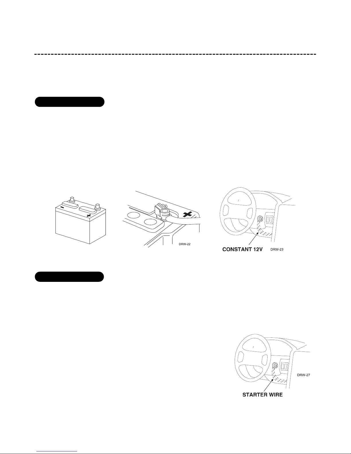
obtaining constant 12V . . . . . . . . . . . . . . . . 6
finding the starter wire . . . . . . . . . . . . . . . . 6
finding the 12V switched ignition wire . . . . . . 7
finding the accessory wire. . . . . . . . . . . . . . . 7
finding a (+) parking light wire . . . . . . . . . . . 8
finding the tachometer wire . . . . . . . . . . . . . 8
finding the wait-to-start bulb wire for diesels . 9
pprriimmaarryyhhaarrnneessss((HH11))wwiirriinnggddiiaaggrraamm...........
.......1100
44--ppiinnssaatteelllliitteehhaarrnneessssddiiaaggrraamm..........................1100
hheeaavvyyggaauuggeerreellaayyssaatteelllliitteewwi
irriinnggddiiaaggrraamm..........1111
ddoooorrlloocckkhhaarrnneessss,,33--ppiinnccoonnnneeccttoorr....................1111
rreemmootteessttaarrtthhaarrnne
essss((HH22))wwiirriinnggddiiaaggrraamm............1111
pprriimmaarryyhhaarrnneessss((HH11)),,99--ppiinnccoonnnneeccttoorr................1122
rreellaayys
saatteelllliitteeiinntteerrffaaccee....................................1166
rreemmootteessttaarrtthhaarrnneessss((HH22)),,55--ppiinnccoonnnneeccttoorr.
.........1177
nneeuuttrraallssaaffeettyysswwiittcchhiinntteerrffaaccee..........................1188
general motors trucks, SUVs, and column
shifting passenger cars . . . . . . . . . . . . . . . . 20
pre-1996 dodge dakota pickups with 2.5 liter
motors . . . . . . . . . . . . . . . . . . . . . . . . . . . 20
bbyyppaassssiinnggGGMMvveehhiicclleeaannttii-
-tthheeffttssyysstteemmss((VVAATTSS))....2211
11999955aannddnneewweerrvveehhiicclleeaannttii--tthheeffttssyysstteemmss
((iimmmmoobbiilliizzeerrss))..................................................2222
passlock I and passlock II (PL-1 and PL-2) . . 22
passkey III (PK-3), transponder-based systems22
ooppttiioonnaallaannttii--ggrriinnddrreellaayy..................................223
3
pprrooggrraammmmiinnggjjuummppeerrss........................................2244
light flash (+)/(-) . . . . . . . . . . . . . . . . . . . 24
tach threshold on/off . . . . . . . . . . . . . . . . . 24
pplluugg--iinnpprrooggrraammsswwiittcchh....................................2255
ttrraannssmmiitttteerr//rreecceeiivveerrlleeaarrnnrroouuttiinnee......................2266
ttaacchhlleeaarrnniinngg..
................................................2288
to learn the tach signal . . . . . . . . . . . . . . . 28
ooppeerraattiinnggsseettttiinnggsslleeaarrnnrroouuttiinnee........................2288
ffeeaattuurreessmmeennuu..................................................3300
ffeeaattuurreeddeessccrriippttiioonnss...
.......................................3311
sshhuuttddoowwnnddiiaaggnnoossttiiccss......................................
..3333
rreeaarrddeeffooggggeerrccoonnttrrooll........................................3344
ttiimmeerrmmooddee.....................
.................................3355
ssaaffeettyycchheecckk....................................................
3355
ttrroouubblleesshhoooottiinngg................................................3366
wwiirriinnggqquuiicckkrreeffeerreenncceegguuiiddee...
...........................3399
© 2005 Directed Electronics—all rights reserved 33
wwhhaattiissiinncclluuddeedd
■TThheeccoonnttrroollmmoodduullee((sseeeeddiiaaggrraamm))
■OOnnee447733VVrreemmootteettrraannssmmiitttteerr
■TThheepplluugg--iinnpprrooggrraammsswwiittcchh
■AAhhooooddp
piinnsswwiittcchh
■AAttoogggglleeoovveerrrriiddeesswwiittcchh
■XXRR++aanntteennnnaarreecceeiivveerr
6-pin relay output
4-pin satellite/
harness
9-pin main harness
5-pin remote start
harness
4-pin/3-wire
receiver port
3-pin/2-wire door
lock harness
2-pin BLU
program plug
status L D
44© 2005 Directed Electronics—all rights reserved
wwaarrnniinngg!!ssaaffeettyyffiirrsstt
The following safety warnings must be observed at all times:
■Due to the complexity of this system, installation of this product must only be performed by an authorized
Directed Electronics dealer.
■When properly installed, this system can start the vehicle via a command signal from the remote control
transmitter. Therefore, never operate the system in an area that does not have adequate ventilation. The fol-
lowing precautions are the sole responsibility of the user; however, authorized Directed Electronics dealers
should make the following recommendations to all users of this system:
1. Never operate the system in an enclosed or partially enclosed area without ventilation (such as a garage).
2. When parking in an enclosed or partially enclosed area or when having the vehicle serviced, the remote
start system must be disabled using the installed toggle switch.
3. It is the user's sole responsibility to properly handle and keep out of reach from children all remote
control transmitters to assure that the system does not unintentionally remote start the vehicle.
4. TTHHEEUUSSEERRMMUUSSTTIINNSSTTAALLLLAACCAARRBBOONNMMOONNOOXXIIDDEEDDEETTEECCTTOORRIINNOORRAABBOOUUTTTTHHEELLIIVVIINNGGAARREEAAAADDJJAACCEENNTTTTOO
T
THHEEVVEEHHIICCLLEE..AALLLLDDOOOORRSSLLEEAADDIINNGGFFRROOMMAADDJJAACCEENNTTLLIIVVIINNGGAARREEAASSTTOOTTHHEEEENNCCLLOOSSEEDDOORRPPAARRTTIIAALLLLYY
EENNCCLLOOSSEEDDVVEEHHIIC
CLLEESSTTOORRAAGGEEAARREEAAMMUUSSTTAATTAALLLLTTIIMMEESSRREEMMAAIINNCCLLOOSSEEDD..
■Use of this product in a manner contrary to its intended mode of operation may result in property damage,
personal injury, or death. Except when performing the Safety Check outlined in this installation guide, (1)
Never remotely start the vehicle with the vehicle in gear, and (2) Never remotely start the vehicle with the
keys in the ignition. The user will be responsible for having the neutral safety feature of the vehicle period-
ically checked, wherein the vehicle must not remotely start while the car is in gear. This testing should be
performed by an authorized Directed Electronics dealer in accordance with the Safety Check outlined in this
product installation guide. If the vehicle starts in gear, cease remote start operation immediately and consult
with the user to fix the problem immediately.
■After the remote start module has been installed, test the remote start module in accordance with the Safety
Check outlined in this installation guide. If the vehicle starts when performing the Neutral Safety Shutdown
Circuit test, the remote start unit has not been properly installed. The remote start module must be removed
or properly reinstalled so that the vehicle does not start in gear. All installations must be performed by an
authorized Directed Electronics dealer. OOPPEERRAATTIIOONNOOFFTTHHEERREEMMOOTTEESSTTAARRTTMMOODDUULLEEIIFFTTHHEEV
VEEHHIICCLLEESSTTAARRTTSSIINN
GGEEAARRIISSCCOONNTTRRAARRYYTTOOIITTSSIINNTTEENNDDEEDDMMOODDEEOOFFOOPPEERRAATTIIOONN..OOPPEERRAATTIINNGGTTHHEERREEMMOOTTEESSTTAARRTTSSYYSST
TEEMMUUNNDDEERR
TTHHEESSEECCOONNDDIITTIIOONNSSMMAAYYRREESSUULLTTIINNPPRROOPPEERRTTYYDDAAMMAAGGEEOORRPPEERRSSOONNAALLIINNJJUURRYY..IIMMMMEEDDIIAATTEELLYYCCEEAASSEETTHHEEUUS
SEE
OOFFTTHHEEUUNNIITTAANNDDRREEPPAAIIRROORRDDIISSCCOONNNNEECCTTTTHHEEIINNSSTTAALLLLEEDDRREEMMOOTTEESSTTAARRTTMMOODDUULLEE..DDIIRREECCTTEEDDEELLEECCTTRROONNIICCSS,,
IINNCC.
.WWIILLLLNNOOTTBBEEHHEELLDDRREESSPPOONNSSIIBBLLEEOORRPPAAYYFFOORRIINNSSTTAALLLLAATTIIOONNOORRRREEIINNSSTTAALLLLAATTIIOONNCCOOSSTTSS..
© 2005 Directed Electronics—all rights reserved 55
iinnssttaallllaattiioonnppooiinnttssttoorreemmeemmbbeerr
IIMMPPOORRTTAANNTT!!This product is designed for fuel-injected, automatic transmission vehicles only.
Installing it in a standard transmission vehicle is dangerous and is contrary to its intended use.
BBeeffoorreebbeeggiinnnniinnggtthheeiinnssttaallllaattiioonn::
■Please read this entire installation guide before beginning the installation. The installation of this remote
start system requires interfacing with many of the vehicle’s systems. Many new vehicles use low-voltage or
multiplexed systems that can be damaged by low resistance testing devices, such as test lights and logic
probes (computer safe test lights). Test all circuits with a high quality digital multi-meter before making con-
nections.
■Do not disconnect the battery if the vehicle has an anti-theft-coded radio. If equipped with an air bag, avoid
disconnecting the battery if possible. Many airbag systems will display a diagnostic code through their
warning lights after they lose power. Disconnecting the battery requires this code to be erased, which can
require a trip to the dealer.
■Remove the dome light fuse. This prevents accidentally draining the battery.
■Roll down a window to avoid being locked out of the vehicle.
AAfftteerrtthheeiinnssttaallllaattiioonn::
■Test all functions. The "Using Your System" section of the Owner's Guide is very helpful when testing.
■Complete the vehicle
Safety Check
outlined in this manual prior to the vehicle reassembly.
66© 2005 Directed Electronics—all rights reserved
ffiinnddiinnggtthheewwiirreessyyoouunneeeedd
IIMMPPOORRTTAANNTT!!Do not use a 12V test light or logic probe (computer safe test light) to locate these
wires! All testing described in this manual assumes the use of a digital multimeter.
We recommend two possible sources for 12V constant: The (+) terminal of the battery, or the constant 12V supply
to the ignition switch. Always install a fuse within 12 inches of this connection. If the fuse will also be power-
ing other circuits, such as door locks, a power window module, or a Nite-Lite® headlight control system, fuse
accordingly.
IIMMPPOORRTTAANNTT!!Do not remove the fuse holder on the red wire. It ensures that the control module
has its own fuse, of the proper value, regardless of how many accessories are added to the main
power feed.
The starter wire provides 12V directly to the starter or to a relay controlling starter. In some vehicles, it is
necessary to power a cold start circuit. A cold start circuit will test exactly like a starter circuit, but it does not
control the starter. Instead, the cold start circuit is used to prime the fuel injection system for starting when the
vehicle is cold.
HHoowwttooffiinnddtthheessttaarrtteerrwwiirreewwiitthhyyoouurrmmuullttiimmeetteerr::
1. Set to DCV or DC voltage (12V or 20V is fine).
2. Attach the (-) probe of the meter to chassis ground.
3. Probe the wire you suspect of being the starter wire. The steering
column is an excellent place to find this wire. Remember you do not
need to interrupt the starter at the same point you test it. Hiding
your starter kill relay and connections is always recommended.
4. Turn the ignition key switch to the start position. Make sure the car
ffiinnddiinnggtthheessttaarrtteerrwwiirree
oobbttaaiinniinnggccoonnssttaanntt1122VV
© 2005 Directed Electronics—all rights reserved 77
is not in gear! If your meter reads (+)12V, go to the next step. If it doesn’t, probe another wire.
5. Cut the wire you suspect of being the starter wire.
6. Attempt to start the car. If the starter engages, reconnect it and go back to Step 3. If the starter does not
turn over, you have the right wire.
The ignition wire is powered when the key is in the run or start position. This is because the ignition wire powers
the ignition system (spark plugs, coil) as well as the fuel delivery system (fuel pump, fuel injection computer).
Accessory wires lose power when the key is in the start position to make more current available to the starter motor.
HHoowwttooffiinndd((++))1122VViiggnniittiioonnwwiitthhyyoouurrmmuullttiimmeetteerr::
1. Set to DCV or DC voltage (12V or 20V is fine).
2. Attach the (-) probe of the meter to chassis ground.
3. Probe the wire you suspect of being the ignition wire. The steering
column harness or ignition switch harness is an excellent place to find
this wire.
4. Turn the ignition key switch to the run position. If your meter reads
(+)12V, go to the next step. If it does not read (+)12V, probe another wire.
5. Now turn the key to the start position. The meter display should stay
steady, not dropping by more than a few tenths of a volt. If it drops close
to or all the way to zero, go back to Step 3. If it stays steady at (+)12V, you have found an ignition wire.
An accessory wire will show (+)12V when the key is in the accessory and run positions. It will not show (+)12V
during the cranking cycle. There will often be more than one accessory wire in the ignition harness. The correct
accessory wire will power the vehicle's climate control system. Some vehicles may have separate wires for the
blower motor and the air conditioning compressor. In such cases, it will be necessary to add a relay to power the
second accessory wire.
ffiinnddiinnggtthheeaacccceessssoorryywwiirree
ffiinnddiinnggtthhee1122VVsswwiittcchheeddiiggnniittiioonnwwiirree
88© 2005 Directed Electronics—all rights reserved
Most vehicles use a (+) parking light circuit. The (+) parking light wire is often found near the light switch. In
many vehicles the light switch is built into the turn signal lever; in these vehicles the parking light wire can be
found in the steering column. The same wire can often be accessed in the kick panel or running board.
NNOOTTEE::Many Toyotas and other Asian vehicles, send a (-) signal from the switch to a relay. The
relay then sends (+)12V to the bulbs. Whenever you have difficulty finding a (+) parking light
wire near the switch, simply test the wires at any switch or control panel that is lit by the instru-
ment panel lighting. Remember, you need a (+) parking light wire that does not vary with the
dimmer setting.
HHoowwttooffiinnddaa((++))ppaarrkkiinngglliigghhttffllaasshhwwiirreewwiitthhyyoouurrmmuullttiimmeetteerr::
1. Set to DCV or DC voltage (12V or 20V is fine).
2. Attach the (-) probe of the meter to chassis ground.
3. Probe the wire you suspect of being the parking light wire. Usually, the area near the headlight/parking light
switch is an excellent area to start, as is the kick panel.
4. Turn on the parking lights. If your meter shows (+)12V, turn off the parking lights and make sure it goes back
to zero.
5. If it does return to zero, turn the parking lights back on and, using the dash light dimmer control, turn the
brightness of the dash lights up and down. If the meter changes more than a volt when using the dimmer,
look for another wire. If it stays relatively close to (+)12V, you have found your parking light wire.
NNOOTTEE::Vehicles that use a (-) signal from the switch to the factory relay may be interfaced
directly. (See H1/5 WHITE wire of Primary Harness (H1) Wire Connection Guide section.)
To test for a tachometer wire, a multimeter capable of testing AC voltage must be used. The tachometer wire will
show between 1V and 6V AC. In multi-coil ignition systems, the system can learn individual coil wires. Individual
coil wires in a multi-coil ignition system will register lower amounts of AC voltage. Also, if necessary, the system
ffiinnddiinnggtthheettaacchhoommeetteerrwwiirree
ffiinnddiinnggaa((++))ppaarrkkiinngglliigghhttwwiirree
© 2005 Directed Electronics—all rights reserved 99
can use a fuel injector control wire for engine speed sensing. Common locations for a tachometer wire are the
ignition coil itself, the back of the gauges, engine computers, and automatic transmission computers.
IIMMPPOORRTTAANNTT!!Do not test tachometer wires using a test light or logic probe. The vehicle will be
damaged.
HHoowwttooffiinnddaattaacchhoommeetteerrwwiirreewwiitthhyyoouurrmmuullttiimmeetteerr::
1. Set to ACV or AC voltage (12V or 20V is fine).
2. Attach the (-) probe of the meter to chassis ground.
3. Start and run the vehicle.
4. Probe the wire you suspect of being the tachometer wire with the red probe of the meter.
5. If this is the correct wire the meter will read between 1V and 6V.
In diesel vehicles it is necessary to interface with the wire that turns on the WAIT-TO-START light in the dash-
board. This wire illuminates the bulb until the vehicle’s glow plugs are properly heated. When the light goes out
the vehicle can be started. This wire is always available at the connector leading to the bulb in the dashboard.
It can also be found at the Engine Control Module (ECM) in many vehicles.
TTootteessttaannddddeetteerrmmiinneetthheeppoollaarriittyyoofftthhiissw
wiirree::
1. Set your multimeter to DCV or DC voltage (12 or 20V is fine).
2. Attach the (+) probe of the meter to (+)12V.
3. Probe the wire that you suspect leads to the bulb with the (-) probe of the meter.
4. Turn the ignition switch to the ON position.
5. If the meter indicates 12 volts until the light goes out you have isolated the correct wire and the wire's polar-
ity is negative (ground while the bulb is on).
6. If the meter reads zero volts until the light goes out and then reads 12 volts, you have isolated the correct
wire and the wire's polarity is positive.
ffiinnddiinnggtthheewwaaiitt--ttoo--ssttaarrttbbuullbbwwiirreeffoorrddiieesseellss
1100© 2005 Directed Electronics—all rights reserved
pprriimmaarryyhhaarrnneessss((HH11))wwiirriinnggddiiaaggrraamm
______
______
______
______
______
______
______
______
______
44--ppiinnssaatteelllliitteehhaarrnneessssddiiaaggrraamm
______
______
______
______ PPIINNKKIIGGNNIITTIIOONNTTRRIIGGGGEERR
PPUURRPPLLEESSTTAARRTTEERRTTRRIIGGGGEERR
OORRAANNGGEEAACCCCEESSSSOORRYYTTRRIIGGGGEERR
BBLLUUEESSTTAATTUUSSOOUUTTPPUUTT
11
22
33
44
WWHHIITTEE((++//--))LLIIGGHHTTFFLLAASSHH
BBLLAACCKKGGRROOUUNNDD
RREEDD//WWHHIITTEECCHHAANNNNEELL22((VVAALLIIDDIITTYYOONNLLYY))
WWHHIITTEE//RREEDD((++))AACCTTIIVVAATTIIOONNIINNPPUUTT
GGRRAAYY//BBLLAACCKK((--))WWAAIITTTTOOSSTTAARRTTIINNPPUUTT
WWHHIITTEE//BBLLUUEE((--))AACCTTIIVVAATTIIOONNIINNPPUUTT
YYEELLLLOOWW((++))IIGGNNIITTIIOONNOOUUTT((TTOOAALLAARRMM))
GGRREEEENN//WWHHIITTEEFFAACCTTOORRYYRREEAARRMM
LLIIGGHHTTGGRREEEENN//BBLLAACCKKFFAACCTTOORRYYAALLAARRMMDDIISSAARRMM
HH11//11
HH11//22
HH11//33
HH11//44
HH11//55
HH11//66
HH11//77
HH11//88
HH11//99