Viper 3100 User manual

®
OWNER’S GUIDE MODEL
3100
©2011 Directed Electronics. All rights reserved.
The company behind Viper®Auto Security Systems
is Directed Electronics.
Since its inception, Directed Electronics has had one
purpose, to provide consumers with the finest vehicle
security and car stereo products and accessories
available. The recipient of nearly 100 patents and
Innovations Awards in the field of advanced electronic
technology, Directed Electronics is ISO 9001 registered.
Quality Directed Electronics products are sold and
serviced throughout North America and around
the world.
Vista, CA 92081
www.viper.com
Directed Electronics is an
ISO 9001 registered company.
Directed Electronics is committed to delivering
world class quality products and services that
excite and delight our customers.
NO ONE DARES COME CLOSE
G3100V BL 2011-03

i
© 2011 Directed Electronics. All rights reserved.
Congratulations
Congratulations on the purchase of your state-of-the-art security system.
Reading this Owner’s Guide prior to using your system will help maxi-
mize the use of your system and its many features. For more informa-
tion please visit us online at: www.viper.com
For additional questions please contact your authorized Directed deal-
er. Additional support is also available at: http://support.directed.
com
What you get
s A control module (installed)
s Two 3-button remote controls
s A registration card
s This owner’s guide
AUX AUX Registration
Card
Owner’s
Guide
Replacement remote controls
If additional remote controls (P/N 473V) are desired, please see your
authorized dealer or visit us at www.directedstore.com to order.
G3100V BL 2011-03

1
© 2011 Directed Electronics. All rights reserved.
Contents
Congratulations ................................................................................................... i
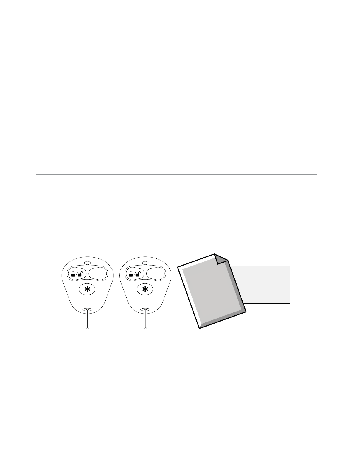
What you get....................................................................................................... i
Getting Started.................................................................................................... 2
Keys to using this manual...................................................................... 2
System Maintenance ............................................................................ 2
Battery Disposal .................................................................................. 2
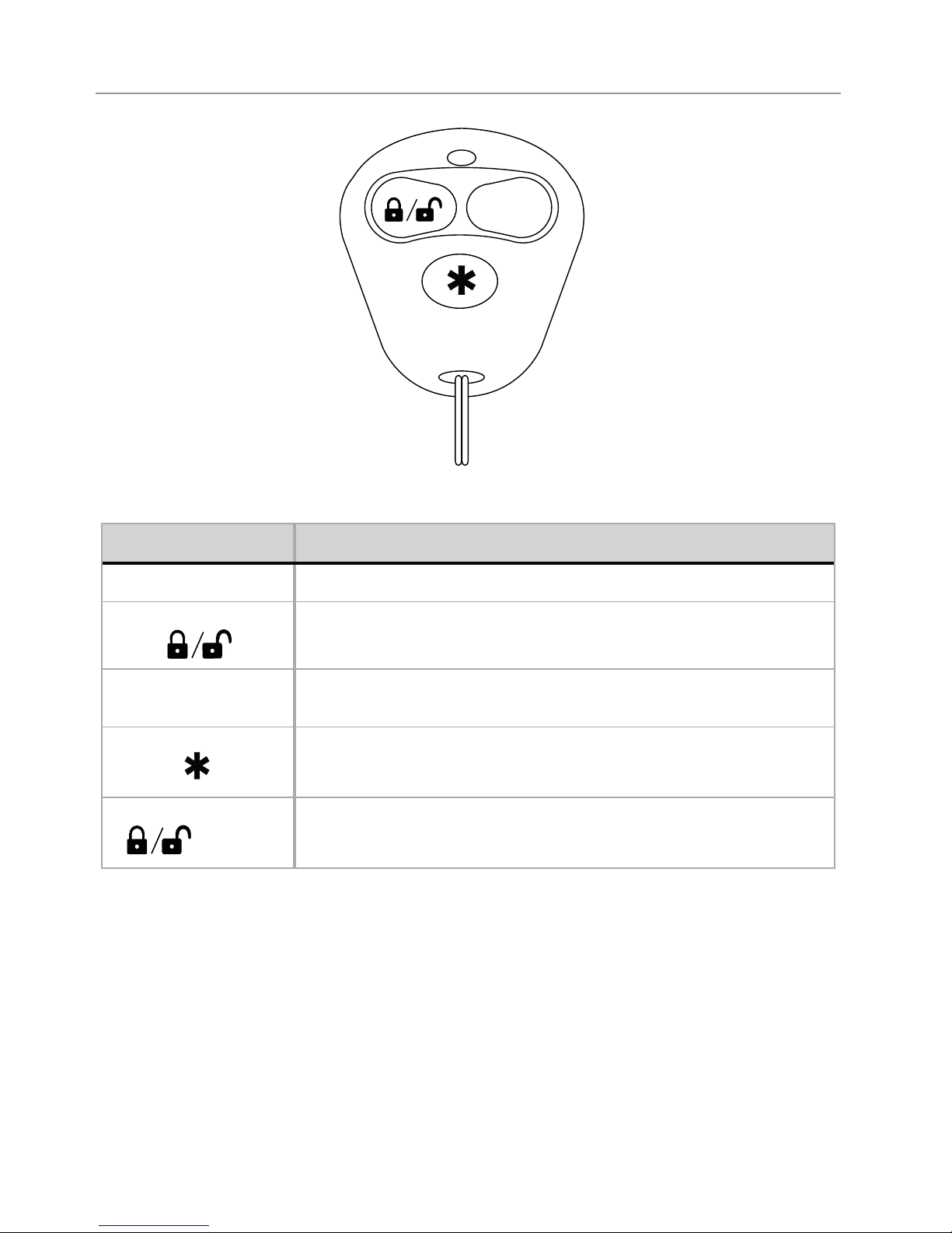
Remote Control ................................................................................................... 3
Using your System............................................................................................... 4
Arm ................................................................................................... 4
Disarm ............................................................................................... 4
AUX Channel 2 ................................................................................... 4
Panic.................................................................................................. 5
Silent Arm/Disarm ............................................................................... 5
AUX Channel 3 ................................................................................... 5
Alarm Features ................................................................................................... 6
Armed Protection ................................................................................. 6
Emergency Override ............................................................................ 7
Trigger Zone Fault Report...................................................................... 7
Alarm Report....................................................................................... 7
Nuisance Prevention Circuitry (NPC)...................................................... 8
Remote and System Operations............................................................................ 9
Passive Arming.................................................................................... 9
Valet Mode ......................................................................................... 9
Comfort Closure ................................................................................ 10
Code Hopping Technology ................................................................. 10
Glossary of Terms.............................................................................................. 10
Government Regulations .................................................................................... 11
Additional Information....................................................................................... 12
Interference....................................................................................... 12
Upgrades ......................................................................................... 12
Water/Heat Resistance ...................................................................... 12
Español ............................................................................................................ 13

2© 2011 Directed Electronics. All rights reserved.
Getting Started
Keys to using this manual
Specific actions (in bold type) and style conventions are used consis-
tently throughout this manual, they are as follows:
s Press: implies pushing in and releasing a button.
s Hold: is used when a button needs to be held in position for an
extended period of time, typically several seconds.
s Italicized words denote section/sub headings in this guide and
can be located through the table of contents.
s An asterisk (*) when used after a word or phrase denotes that
additional details can be found in related sections usually noted
at the bottom of the page or end of the section.
System Maintenance
Your vehicle security system has no specific maintenance require-
ments. The remote control is powered by a 3-volt lithium battery (P/N
CR2032) that will last approximately one year under normal use.
When the battery begins to weaken, the LED on the remote control
will dim and you will notice reduced operating range when using the
remote control.
Battery replacement: Locate the small slot on the side of the remote
control. Insert a small slotted screwdriver or equivalent tool into slot
and pry the case apart. Replace battery while verifying the correct
polarity and then snap case together
Battery Disposal
Directed Electronics cares about the environment. If you
need to dispose of the battery, please do so in accordance
with your municipal requirements for battery disposal.

3
© 2011 Directed Electronics. All rights reserved.
Remote Control
AUX
Feature Description
Transmit LED Active when transmitting information
Activates the Arm/Disarm function and Panic On/Off
AUX Activates Auxiliary Channel 2 output
Activates Panic
+ AUX Activates Auxiliary Channel 3 output

4© 2011 Directed Electronics. All rights reserved.
Using your System
Arm
Press and release .
The alarm arms, doors lock (if connected), and the siren chirps and
parking lights flash once.
If Valet mode* is On, the doors lock without siren chirps, the alarm is
disabled. Exit Valet mode to arm the alarm normally.
If a trigger zone fault is detected the siren chirps once again and the
Status LED generates a Trigger Zone Fault report**.
Disarm
When the system is already armed, Press and release .
The alarm disarms, doors unlock (if connected), and the siren chirps
and parking lights flash twice.
An Alarm Report** alert of 4 or 5 siren chirps will replace the normal
disarm chirps if the alarm was triggered.
AUX Channel 2
Press and hold AUX .
The Trunk opens (if connected) when this button is pressed for 2 sec-
onds.

5
© 2011 Directed Electronics. All rights reserved.
Panic
Press and hold or .
If you are threatened in or near your vehicle, you can trigger Panic
output on your security system to attract attention. The siren will sound
and the parking lights will flash for 30 seconds. Press and release
again to stop the output.
Silent Arm/Disarm
Press and release AUX, then press and release .
The system arms or disarms without chirping the siren. To permanently
turn off the arm and disarm chirps, contact your installation dealer.
Note Silent Arming also bypass the Sensor Warn-away
output**.
AUX Channel 3
Press and release + AUX.
The Channel 3 output will pulse to activate connected accessory mod-
ules. Press and hold the button, the output remains active until the
button is released (for a maximum of 30 seconds).
* See Remote and System Operations for details.
** See Alarm Features for details.

6© 2011 Directed Electronics. All rights reserved.
Alarm Features
Armed Protection
Status LED: The Status LED flashes as a visual indicator that your ve-
hicle’s security system is active.
Starter Kill: The Failsafe starter kill relay prevents the engine from
starting.
Note May require additional parts and installation
Sensor triggers: The onboard shock sensor can distinguish minor im-
pacts from major impacts to the vehicle exterior. Minor impacts causes
the system to emit a Warn-away output. Major impacts caused for
example by a forcible entry attempt, results in a Full Trigger output.
Point of entry triggers: Opening the hood or trunk causes a Full Trig-
ger output, while opening a Door or turning on the Ignition causes
the siren to chirp 3 seconds before beginning the Full Trigger output.
This 3 second delay allows time to disarm and silence the siren in
case of accidental trigger.
Sensor Warn-away output: When the system sensors detect a Warn-
away, it triggers the siren chirps and the parking lights flash for 3
seconds.
Full Trigger output: An alarm Full Trigger sounds the siren and flashes
the parking lights for 30 seconds.

7
© 2011 Directed Electronics. All rights reserved.
Emergency Override
The following procedure disarms the system when a programmed re-
mote is not available.
1. Turn the ignition On.
2. Press and release the Valet button once.
3. The siren output ceases and the system is disarmed.
Note As a precaution, if programmed for Passive Arming the sys-
tem should be placed into Valet Mode until a remote is
available.
Trigger Zone Fault Report
When armed by remote command the system runs a status check of
the alarm trigger zones (see Table of Zones on next page). Open
zones (usually caused by dome light delay or open trunk) are by-
passed and reported via the status LED, while all other trigger zones
remain active and are monitored to protect the vehicle. Should an
open zone self correct (such as dome light turns off), it becomes active
and is then monitored normally.
The siren chirps once again a few seconds following the arming chirps
as an audible alert, and the status LED flashes in groups to indicate
the zone number.
Alarm Report
If the alarm was triggered while armed, it will be reported when the
alarm is disarmed via siren chirps, parking light and status LED flashes.
The siren chirps 4 times (or 5 times if NPC On, See Nuisance Preven-
tion (NPC) on next page), the parking lights flash 3 times, and the
status LED flashes in groups to indicate the last two zones that were
triggered (see Table of Zones on next page). The report output will
repeat for each disarm operation until the ignition is turned on.

8© 2011 Directed Electronics. All rights reserved.
Table of Zones
Zone # (led flashes) Zone Name
1 Trunk/Sensor 2
2 Shock Sensor
3 Door
5 Ignition
Note: The Warn-away trigger does not report on the LED.
Nuisance Prevention Circuitry (NPC)
NPC monitors all alarm zones and, if any are triggered excessively,
bypasses them until corrected. If a point of entry (trunk, hood, door)
is left open following a forced entry, it is bypassed. It becomes active
again only after being closed.
Bypassed sensors automatically reset after one hour, and after the
vehicle is driven. Disarming then re-arming the alarm does not reset
bypassed sensors.

9
© 2011 Directed Electronics. All rights reserved.
Remote and System Operations
Passive Arming
Park and exit the vehicle, after the doors are closed the Passive arming
countdown begins. The led flashes quickly and after 30 seconds the
system arms itself.
Anytime before the system arms you can re-enter the vehicle or
open the trunk to load or unload items and, after closing passive arm-
ing resumes.
To stay secure in case of accidental disarming the system, if a
door is not opened within 30 seconds the system re-arms itself.
Note: This is a programmable option.
Valet Mode
Valet mode can be entered and exited by performing the Remote Valet
command or manually using the vehicle key and the valet button. Valet
Mode defeats the alarm features while the convenience features still
operate normally.
Use the following steps to manually enter and exit Valet Mode:
1. Turn the ignition On and then Off
2. Immediately press and release the valet button once
3. The status LED turns On when entering and Off when exiting.
You can also enter or exit Valet Mode by using the remote:
1. Open any vehicle door.
2. Press and then press AUX. Press again.
The LED system status indicator lights solid when you enter Valet Mode
and turns off when you exit Valet Mode.

10 © 2011 Directed Electronics. All rights reserved.
Comfort Closure
The optional Comfort Closure feature imitates turning the key in the door cylin-
der or holding the lock button of an Original Equipment Manufacturer (OEM)
keyless entry. It will automatically close the windows and sunroof on vehicles
with this type of OEM convenience feature.
Code Hopping Technology
Code Hopping Technology has been developed to increase the secu-
rity of the unit. If buttons on the remote are pressed many times when
out of range, or the battery is removed, the remote may get temporar-
ily out of sync and fail to operate the system. To re-synchronize the
remote, press several times within range of the vehicle. The
system will automatically re-synchronize and the remote will respond
normally.
Glossary of Terms
Document Terminology
Control Module The “brain” of your system. Usually hidden underneath the
dash area of the vehicle. It houses the microprocessor which
monitors your vehicle and controls all of the system’s func-
tions.
Remote Control A hand-held, remote control which operates the various func-
tions of your system.
Status LED A light used to indicate the status of your system.
Valet Button A small push button located in your vehicle. It is used to over-
ride (disarm) the alarm when a remote is not available or to
enter or exit Valet Mode.

11
© 2011 Directed Electronics. All rights reserved.
Government Regulations
This device complies with Part 15 of FCC rules. Operation is subject to the fol-
lowing two conditions: (1) This device may not cause harmful interference, and
(2) This device must accept any interference received, including interference
that may cause undesirable operation.
This equipment has been tested and found to comply with the limits for a
class B digital device, pursuant to Part 15 of the FCC Rules. These limits are
designed to provide reasonable protection against harmful interference in a
residential installation. This equipment generates and can radiate radio fre-
quency energy and, if not installed and used in accordance with the instruction
manual, may cause harmful interference to radio communications. However,
there is no guarantee that interference will not occur in a particular installa-
tion. If this equipment does cause harmful interference to radio or television,
which can be determined by turning the equipment OFF and ON, the user is
encouraged to try to correct the interference by one or more of the following
measures:
s Reorient or relocate the receiving antenna.
s Increase the separation between the equipment and receiver.
s Connect the equipment into an outlet on a circuit different from that to
which the receiver is connected.
s Consult the dealer or an experienced radio / TV technician for help.
Remote Controls
To satisfy FCC RF exposure compliance requirements, this device should be
used in hand-held, hand operated configurations only. The device and its an-
tenna must maintain a separation distance of 20 cm or more from the person’s
body, except for the hand and wrists, to satisfy RF exposure compliance. This
device is designed to be used in a person’s hands and its operating configu-
rations do not support normal transmissions while it is carried in pockets or
holsters next to a person’s body.

12 © 2011 Directed Electronics. All rights reserved.
Additional Information
Interference
All radio devices are subject to interference which could affect proper
performance.
Upgrades
Any upgrades to this product must be performed by an authorized
Directed dealer. Do not attempt to perform any unauthorized modifica-
tions to this product.
Water/Heat Resistance
This product is not designed to be water and/or heat-resistant. Please
take care to keep this product dry and away from heat sources. Any
damage from water or heat will void the warranty.

Español
Modelo 3100
Guía del Propietario

i
© 2011 Directed Electronics. Reservados todos los derechos.
Felicitaciones
Felicitaciones por la compra de su sistema de arranque a distancia
y entrada sin llave con tecnología de vanguardia. Leer la guía del
propietario antes de utilizar el sistema maximiza la implementación
y las diversas características del sistema. Hay más información en
www.viper.com.
Si tiene preguntas, comuníquese con el distribuidor autorizado de
Directed. También hay apoyo adicional en http://support.directed.
com.
Que Incluye:
s Modulo de control (instalado)
s Dos controles remotos de 3 botones
s Tarjeta de registro
s Esta guía del propietario
AUX AUX Registration
Card
Owner’s
Guide
Reemplazo de controles remotos
Si desea más controles remotos, llame al distribuidor autorizado o
vaya a www.directedstore.com para pedirlos. El número es (1 Vía)
473V.

1
© 2011 Directed Electronics. Reservados todos los derechos.
Contenido
Felicitaciones ....................................................................................................... i
Que Incluye: ........................................................................................................ i
Inicio.................................................................................................................. 2
Claves para utilizar este manual............................................................ 2
Mantenimiento del sistema.................................................................... 2
Desecho de la pila............................................................................... 2
Control Remoto ................................................................................................... 3
Utilizando el Sistema........................................................................................... 4
Armado.............................................................................................. 4
Desarmado......................................................................................... 4
AUX (Canal 2) .................................................................................... 4
Modo Pánico ...................................................................................... 5
Modo Silencioso.................................................................................. 5
AUX (Canal 3) .................................................................................... 5
Características de la Alarma ............................................................................... 6
Protección armada............................................................................... 6
Anulación de emergencia..................................................................... 7
Reporte de infracción de zona de activación .......................................... 7
Reporte de alarma............................................................................... 7
Circuito de Prevención de Molestias (CPM)............................................. 8
Operaciones a distancia y de sistema................................................................... 9
Armado pasivo.................................................................................... 9
Modalidad Valet.................................................................................. 9
Cierre de comodidad......................................................................... 10
Tecnología de salto de códigos ........................................................... 10
Glosario de Términos ........................................................................................ 11
Reglamentos del gobierno.................................................................................. 12
Información adicional........................................................................................ 13
Interferencia ..................................................................................... 13
Actualizaciones ................................................................................ 13
Resistencia al agua y al calor.............................................................. 13

2© 2011 Directed Electronics. Reservados todos los derechos.
Inicio
Claves para utilizar este manual
Las acciones específicas (en negrita) y las convenciones de estilo que
se utilizan uniformemente en este manual son las siguientes:
s Oprimir significa oprimir y luego soltar un botón.
s Mantener oprimido significa mantener un botón en posición du-
rante un cierto período de tiempo, por lo general, varios segun-
dos.
s Las palabras en cursiva denotan secciones o subtítulos de esta
guía que se pueden encontrar por medio del índice.
s Los asteriscos (*) se ponen después de una palabra o una frase
para denotar detalles adicionales que se pueden encontrar en
secciones afines. Estos detalles adicionales por lo general se
indican a pie de página o al final de la sección.
Mantenimiento del sistema
El sistema de seguridad de su vehículo no tiene requisitos específicos
de mantenimiento. El control remoto tiene una pila de litio de 3 V
(N/P CR2032) que dura aproximadamente un año en condiciones
normales de uso. Cuando la pila comienza a debilitarse, el indicador
luminoso del control remoto se atenúa y se nota una reducción del
alcance del control remoto.
Cambio de la pila: Ubique la pequeña ranura en el lado del control
remoto. Inserte un destornillador plano pequeño o una herramienta
equivalente en la ranura y haga palanca para abrir la caja. Al cam-
biar la pila verifique la polaridad, luego cierre la caja a presión.
Desecho de la pila
Directed Electronics se preocupa por el medio ambiente. Si tiene que

3
© 2011 Directed Electronics. Reservados todos los derechos.
desechar la pila, hágalo de acuerdo con los requisitos municipales
de desecho de pilas.
Control Remoto
AUX
Característica Descripción
Indicador LED Activo al transmitir información.
Este botón controla una armado/desarmado/pánico.
AUX Este botón controla una salida auxiliar (canal 2).
Este botón controla una pánico.
+ AUX Éstos botónes controla una salida auxiliar extra (canal 3).

4© 2011 Directed Electronics. Reservados todos los derechos.
Utilizando el Sistema
Armado
Oprima y suelte el botón
La alarma se activa, las puertas se bloquean (si están conectadas),
la sirena o el claxon suena y las luces de estacionamiento destellan
una vez.
Si la modalidad de valet está activada, las puertas se bloquean.
Salga de la modalidad de valet para armar o bloquear la alarma
normalmente. Si se detecta una infracción de zona de activación, la
sirena trina una vez más y el indicador LED reporta la infracción de
zona de activación**
Desarmado
Oprima ysuelte el botón (Cuando armado)
La alarma se desarma, las puertas se desbloquean (si están conecta-
das), la sirena o el claxon suena y las luces de estacionamiento destel-
lan 2 veces. Se desactiva la función de pánico, si estaba activada.
Una alerta de reporte de alarma** de 4 ó 5 trinos de sirena reem-
plaza los trinos de desarmado normal si ha habido una activación
de alarma. .
AUX (Canal 2)
Oprima ymantenga oprimido el botón AUX
Activa la salida auxiliar, que puede ser la apertura del maletero (si
está conectada).
Table of contents
Languages:
Other Viper Car Alarm manuals
Popular Car Alarm manuals by other brands

CrimeStopper
CrimeStopper CM-2500 user manual

Escort
Escort entourage PS quick start guide

Fortin
Fortin FSA-206L FSA-208 user guide

CrimeStopper
CrimeStopper Fortress FS-10 Installation & operating instructions

Black Widow
Black Widow BW-1020 NEW AVENGER installation manual

Directed Electronics
Directed Electronics 4100 installation guide

Sanji
Sanji AT 70 User instructions

Avital
Avital AviStart 3100 Install Addendum

Freedom
Freedom Freedom 411atv Owner's manual & wiring instructions

Directed Electronics
Directed Electronics G312R Owner's installation guide

Audiovox
Audiovox Auto Security AA-931 Installation guide & owner's manual

Black Widow
Black Widow BW-1400 CHALLENGER user manual