logo
Brands
  1. Home
  2. •
  3. Brands
  4. •
  5. Viper
  6. •
  7. Car Alarm
  8. •
  9. Viper 320HV User manual

Viper 320HV User manual

Other Viper Car Alarm manuals

Viper 500 ESP User manual

Viper

Viper 500 ESP User manual

Viper 200 MAX User manual

Viper

Viper 200 MAX User manual

Viper 5606V User manual

Viper

Viper 5606V User manual

Viper Responder 350 User manual

Viper

Viper Responder 350 User manual

Viper 300 ESP User manual

Viper

Viper 300 ESP User manual

Viper 4806V User manual

Viper

Viper 4806V User manual

Viper SmartStart 3000 Series User manual

Viper

Viper SmartStart 3000 Series User manual

Viper 4806V User manual

Viper

Viper 4806V User manual

Viper 5901 User manual

Viper

Viper 5901 User manual

Viper 560XV User manual

Viper

Viper 560XV User manual

Viper 4218V User manual

Viper

Viper 4218V User manual

Viper 1000 User manual

Viper

Viper 1000 User manual

Viper 5501 User manual

Viper

Viper 5501 User manual

Viper 130XV User manual

Viper

Viper 130XV User manual

Viper 550 ESP User manual

Viper

Viper 550 ESP User manual

Viper 160XV User manual

Viper

Viper 160XV User manual

Viper 5104 1-Way User manual

Viper

Viper 5104 1-Way User manual

Viper 790XV User manual

Viper

Viper 790XV User manual

Viper 3100 User manual

Viper

Viper 3100 User manual

Viper 5906V User manual

Viper

Viper 5906V User manual

Viper 1002 User manual

Viper

Viper 1002 User manual

Viper 5900 User manual

Viper

Viper 5900 User manual

Viper 280HF User manual

Viper

Viper 280HF User manual

Viper Directed 4706V User manual

Viper

Viper Directed 4706V User manual

Popular Car Alarm manuals by other brands

Clifford 3606X owner's guide

Clifford

Clifford 3606X owner's guide

Ultra Start 2500M SERIES install guide

Ultra Start

Ultra Start 2500M SERIES install guide

Ultra Start 650 Series owner's manual

Ultra Start

Ultra Start 650 Series owner's manual

Audiovox Prestige Platinum+ APS-511C owner's manual

Audiovox

Audiovox Prestige Platinum+ APS-511C owner's manual

Sparkrite SRA8 Guide

Sparkrite

Sparkrite SRA8 Guide

Federal Signal Corporation Pathfinder Siren Series Installation and maintenance manual

Federal Signal Corporation

Federal Signal Corporation Pathfinder Siren Series Installation and maintenance manual

Falcon Predator XL3 Installer manual

Falcon

Falcon Predator XL3 Installer manual

Audiovox Auto Security XR91 Programming guide

Audiovox

Audiovox Auto Security XR91 Programming guide

Clifford Sabre II owner's manual

Clifford

Clifford Sabre II owner's manual

CrimeStopper CS-8717 Wiring diagram

CrimeStopper

CrimeStopper CS-8717 Wiring diagram

Scytek electronic Vectra X3 product manual

Scytek electronic

Scytek electronic Vectra X3 product manual

Clifford CYBER 2 owner's manual

Clifford

Clifford CYBER 2 owner's manual

Gemini 7057 user manual

Gemini

Gemini 7057 user manual

FlashLogic FLRSBA PRESTIGE Product guide

FlashLogic

FlashLogic FLRSBA PRESTIGE Product guide

Magicar FAI-440 manual

Magicar

Magicar FAI-440 manual

Clifford Nova 3 owner's manual

Clifford

Clifford Nova 3 owner's manual

SECO-LARM 300C owner's manual

SECO-LARM

SECO-LARM 300C owner's manual

Python 660XP owner's guide

Python

Python 660XP owner's guide

https://manuals.online logo
https://manuals.online logoBrands
  • About & Mission
  • Contact us
  • Privacy Policy
  • Terms and Conditions

Copyright 2025 Manuals.Online. All Rights Reserved.

MMooddeell332200HHVV
IInnssttaallllaattiioonnGGuuiiddee
© 2004 Directed Electronics, Inc. Vista, CA N431V 07-04
VVIIPPEERR®®
22© 2004 Directed Electronics, Inc. Vista, CA
ttaabblleeooffccoonntteennttss
Avital
®
, Bitwriter
™
, Stealth Coding Technology
™
, Doubleguard
®
, ESP
™
, FailSafe
®
, Ghost Switch
™
,
Learn Routine
™
, Nite-Lite
®
, Nuisance Prevention Circuitry
®
, NPC
®
, Revenger
®
, Silent Mode
™
, Soft
Chirp
®
, Stinger
®
, Valet
®
, Vehicle Recovery System
®
, VRS
®
, and Warn Away
®
are all Trademarks or
Registered Trademarks of Directed Electronics, Inc.
wwhhaattiissiinncclluuddeedd..................................................................................................................................33
pprriimmaarryyhhaarrnneessss((HH11))wwiirreeccoonnnneeccttiioonngguuiiddee..........
..................................................................................33
ddoooorrlloocckkhhaarrnnees
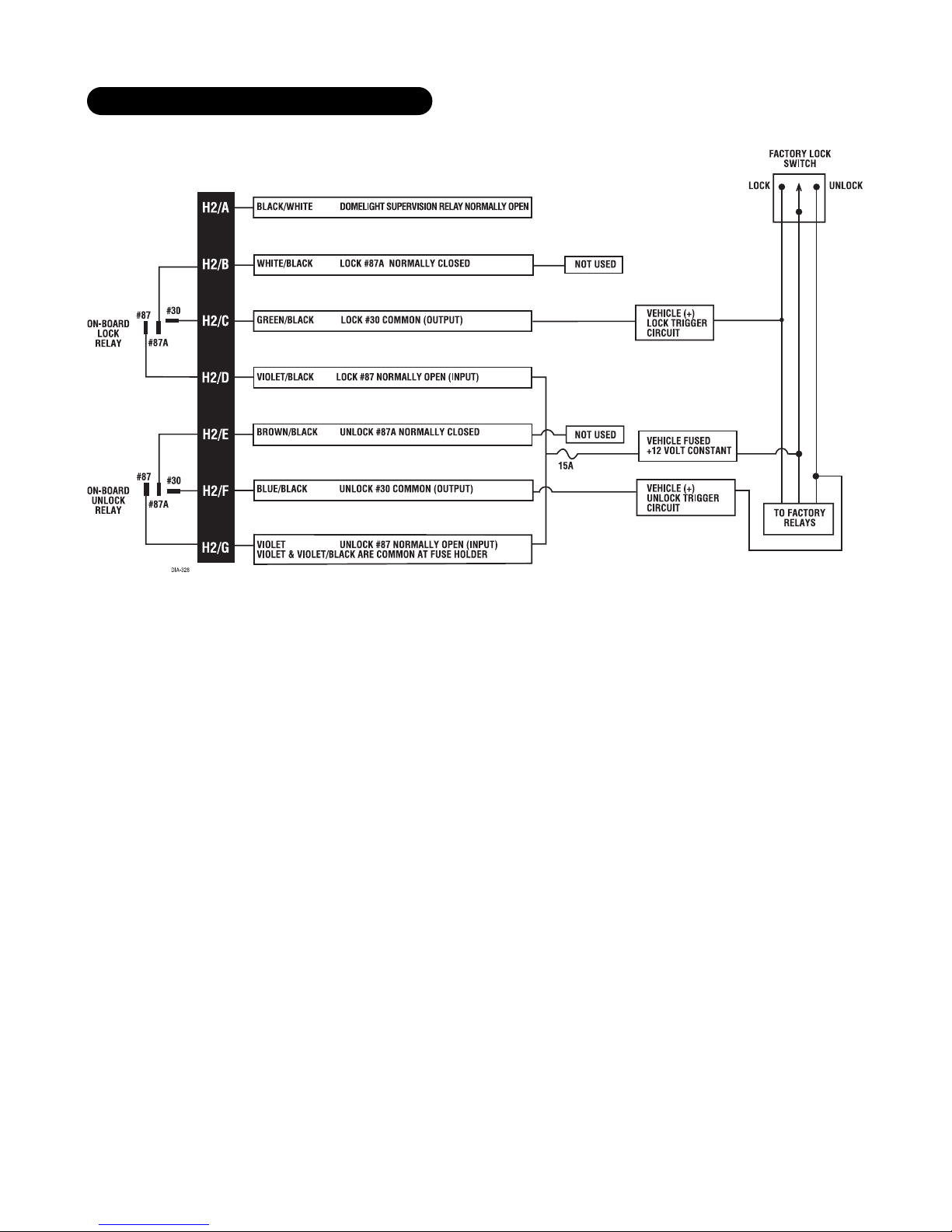
sss((HH22))wwiirreeccoonnnneeccttiioonngguuiiddee........................................................................................88
identifying the door lock system . . . . . . . . . . . . . . . . . . . . . . . . . . . . . . . . . . . . . . . . . . . . . . . . . . . 8
at the switch . . . . . . . . . . . . . . . . . . . . . . . . . . . . . . . . . . . . . . . . . . . . . . . . . . . . . . . . . . . . . . . . 9
type A: positive-triggered, relay-driven system . . . . . . . . . . . . . . . . . . . . . . . . . . . . . . . . . . . . . . . . 10
type B: negative-triggered, relay-driven system . . . . . . . . . . . . . . . . . . . . . . . . . . . . . . . . . . . . . . . . 11
type C: reversing polarity system . . . . . . . . . . . . . . . . . . . . . . . . . . . . . . . . . . . . . . . . . . . . . . . . . . 12
type D: adding one or more after-market actuators. . . . . . . . . . . . . . . . . . . . . . . . . . . . . . . . . . . . . . 13
type E: electrically-activated vacuum . . . . . . . . . . . . . . . . . . . . . . . . . . . . . . . . . . . . . . . . . . . . . . . 14
type F: one-wire system (cut to lock, ground to unlock) . . . . . . . . . . . . . . . . . . . . . . . . . . . . . . . . . . 15
type G: positive (+) multiplex . . . . . . . . . . . . . . . . . . . . . . . . . . . . . . . . . . . . . . . . . . . . . . . . . . . . 16
type H: negative (-) multiplex. . . . . . . . . . . . . . . . . . . . . . . . . . . . . . . . . . . . . . . . . . . . . . . . . . . . 18
pplluugg--iinnLLEEDDaannddvvaalleett//pprrooggrraammsswwiittcchh..............................
....................................................................2233
iinntteerrnnaallpprrooggrraammmmiinnggjjuummppeerr.
...........................................................................................................2233
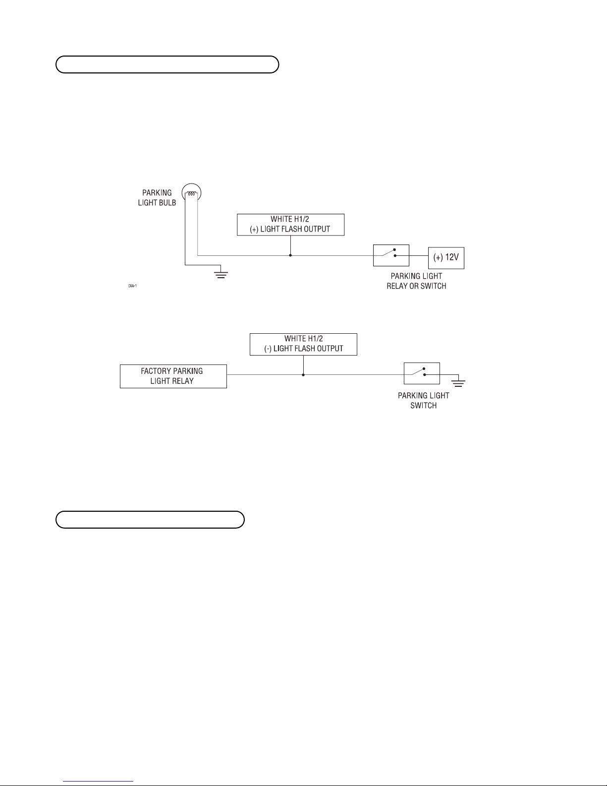
light flash jumper . . . . . . . . . . . . . . . . . . . . . . . . . . . . . . . . . . . . . . . . . . . . . . . . . . . . . . . . . . . . 23
oonn--bbooaarrdddduuaallssttaaggeeiimmppaaccttsseennssoorr.......................................................
...............................................2244
bbyyppaassssiinnggsseennssoorriinnppuuttss...........................
...........................................................................................2244
ttrraannssm
miitttteerr//rreecceeiivveerrlleeaarrnnrroouuttiinnee........................................................................................................2255
33--bbuuttttoonnttrraannssmmiitttteerrccoonnffiigguurraattiioonn...............................
.......................................................................2277
44--bbuuttttoonnttrraannssmmiitttteerrccoonnffi
igguurraattiioonn............................................................................................
..........2277
ssyysstteemmffeeaattuurreesslleeaarrnnrroouuttiinnee..........................................................
....................................................2288
ffeeaattuurreessmmeennuu................................
..................................................................................................229
9
ffeeaattuurreeddeessccrriippttiioonnss...............................................................................
...........................................2299
nnuuiissaanncceepprreevveennttiioonncciirrccuuiittrryy™™........................
....................................................................................3311
ttaabblleeooffzzoonne
ess..................................................................................................................................3322
ttrroouubblleesshhoooottiinngg...................................................
.............................................................................3322
wwiirriinnggqquuiicckkrreeffeerreen
ncceeddiiaaggrraamm............................................................................................................3344
© 2004 Directed Electronics, Inc. Vista, CA 33
wwhhaattiissiinncclluuddeedd
■The control module ■Two 3-button remote transmitters
■The plug-in LED system status indicator ■The plug-in Valet®/Program switch
■An on-board zone 2 impact sensor ■A high-powered siren
■The 12-pin primary harness ■The 7-pin door lock harness
■The 3-pin auxiliary harness ■The plug-in starter interrupt harness
pprriimmaarryyhhaarrnneessss((HH11))wwiirreeccoonnnneeccttiioonngguuiiddee
______
______
______
______
______
______
______
______
______
______
______
______
This wire supplies (-) ground as long as the system is armed. This output ceases as soon as the system is disarmed. This
wire can be used to turn on an optional sensor or to control an optional accessory, such as a window module or pager.
HH11//11OORRAANNGGEE((--))ggrroouunndd--wwhheenn--aarrmmeedd550000mmAAoouuttppuutt
RREEDD//WWHHIITTEE((--))220000mmAACCHHAANNNNEELL22VVAALLIIDDIITTYYOOUUTTPPUUTT
RREEDD((++))1122VVCCOONNSSTTAANNTTPPOOWWEERRIINNPPUUTT
BBRROOWWNN((++))SSIIRREENNOOUUTTPPUUTT
YYEELLLLOOWW((++))IIGGNNIITTIIOONNIINNPPUUTT,,ZZOONNEE55
BBLLAACCKK((--))CCHHAASSSSIISSGGRROOUUNNDDIINNPPUUTT
VVIIOOLLEETT((++))DDOOOORRTTRRIIGGGGEERRIINNPPUUTT,,ZZOONNEE33
BBLLUUEE((--))MMUULLTTIIPPLLEEXXTTRRIIGGGGEERRIINNPPUUTT,,ZZOONNEE11
GGRREEEENN((--))DDOOOORRTTRRIIGGGGEERRIINNPPUUTT,,ZZOONNEE33
BBLLAACCKK//WWHHIITTEEOOUUTTPPUUTTOOFFIINNTTEERRIIOORRLLIIGGHHTTIILLLLUUMMIINNAATTIIOONNRREELLAAYY##3300
WWHHIITTEE//BBLLUUEE((--))220000mmAACCHHAANNNNEELL33VVAALLIIDDIITTYYOOUUTTPPUUTT
WWHHIITTEE((++//--))SSEELLEECCTTAABBLLEELLIIGGHHTTFFLLAASSHHOOUUTTPPUUTT
OORRAANNGGEE((--))550000mmAAGGRROOUUNNDD--WWHHEENN--AARRMMEEDDOOUUTTPPUUTT
HH11//11
HH11//22
HH11//33
HH11//44
HH11//55
HH11//66
HH11//77
HH11//88
HH11//99
HH11//1100
HH11//1111
HH11//1122
44© 2004 Directed Electronics, Inc. Vista, CA
As shipped, this wire should be connected to the (+) parking light wire. If the light flash polarity jumper inside
the control module is moved to the opposite position (see
Internal Programming Jumper
section of this guide),
this wire supplies a (-) 200 mA output. This is suitable for driving (-) light control wires in Toyota, Lexus, BMW,
some Mitsubishi, some Mazda, and other model cars.
((++))PPoossiittiivveeLLiigghhttFFllaasshhOOuuttppuutt
((--))NNeeggaattiivveeLLiigghhttFFllaasshhOOuuttppuutt
NNOOTTEE::For parking light circuits that draw 10 amps or more, the internal jumper must be switched
to a (-) light flash output. (See the Internal Programming Jumper section of this guide.) PP//NN
88661177or a standard automotive SPDT relay must be used on the H1/2 light flash output harness
wire.
This wire provides a (-) 200 mA output whenever the transmitter code controlling Channel 3 is received. This
output will continue as long as that transmission is received. Use for options such as 556611TTValet®Start system,
552299TTor 553300TTpower window controllers, etc.
IIMMPPOORRTTAANNTT!!Never use this wire to drive anything except a relay or a low-current input! The
transistorized output can only provide 200 mA of current, and connecting directly to a solenoid,
motor, or other high-current device will cause it to fail.
HH11//33WWHHIITTEE//BBLLUUEE((--))cchhaannnneell33oouuttppuutt
HH11//22WWHHIITTEE((++//--))sseelleeccttaabblleelliigghhttffllaasshhoouuttppuutt
© 2004 Directed Electronics, Inc. Vista, CA 55
Connect this wire directly to the domelight circuit in the vehicle. The on-board relay will drive circuits up
to 20 amperes. The polarity of this output is determined by the connection of the H2/A input wire in the
Auxiliary Harness.
NNOOTTEE::If the H2/A input wire is not connected, there will be no output on this wire.
Most vehicles use negative door trigger circuits. Connect the green wire to a wire which shows ground when any
door is opened. In vehicles with factory delays on the domelight circuit, there is usually a wire that is unaffected
by the delay circuitry. This wire will report Zone 3.
This wire will respond to a negative input with an instant trigger. Inputs shorter than 0.8 seconds will trigger
the Warn Away response, while triggers longer than 0.8 seconds will instantly trigger the full alarm cycle. This
wire is ideal for hood and trunk pins and will report on Zone 1. This wire can also be used with Directed
Electronic’s 506T Glass Breakage Sensor, as well as other Directed Electronic’s single stage sensors. The H1/6 BLUE
multiplex trigger wire can be used to shunt sensors during operation, using the auxiliary channels. When any of
the auxiliary channels are transmitted, the H1/6 BLUE wire monitors for a ground. If ground is detected within
5 seconds of transmission, the sensors and the multiplex trigger input on the BLUE wire will be shunted until 5
seconds after the ground is removed. This allows the customer to access the trunk, remote start the vehicle, or
roll the windows down without first disarming the alarm. (See
Bypassing Sensor Inputs
section of this guide.)
HH11//66BBLLUUEE((--))mmuullttiipplleexxttrriiggggeerriinnppuutt,,zzoonnee11
HH11//55GGRREEEENN((--))ddoooorrttrriiggggeerriinnppuutt,,zzoonnee33
HH11//44BBLLAACCKK//WWHHIITTEEhhiigghhccuurrrreennttoouuttppuuttffrroommoonn--bbooaarrddiinntteerriioorrlliigghhttiilllluummiinnaattiioonnrreellaayy
66© 2004 Directed Electronics, Inc. Vista, CA
This wire is used in vehicles that have a positive (+) switched domelight circuit. Connect the violet wire to a
wire that shows (+)12V when any door is opened, and ground when the door is closed. This wire will report Zone 3.
Remove any paint and connect this wire to bare metal, preferably with a factory bolt rather than a screw. (Screws
tend to strip or loosen with time.) We recommend grounding all components, including the siren, to the same point.
Connect this wire to an ignition source. This input must show (+)12V with the key in run position and during
cranking. Make sure that this wire cannot be shorted to the chassis at any point. This wire will report Zone 5.
Connect this to the red wire of the siren. Connect the black wire of the siren to (-) chassis ground, preferably at
the same point you connect the control module’s black ground wire.
HH11//1100BBRROOWWNN((++))ssiirreennoouuttppuutt
HH11//99YYEELLLLOOWW((++))iiggnniittiioonniinnppuutt,,zzoonnee55
HH11//88BBLLAACCKK((--))cchhaassssiissggrroouunnddccoonnnneeccttiioonn
HH11//77VVIIOOLLEETT((++))ddoooorrttrriiggggeerriinnppuutt,,zzoonnee33
© 2004 Directed Electronics, Inc. Vista, CA 77
Before connecting this wire, remove the supplied fuse. Connect to the positive battery terminal or the constant
12V supply to the ignition switch.
NNOOTTEE::Always use a fuse within 12 inches of the point you obtain (+)12V power. Do not use the
15A fuse in the harness for this purpose. This fuse protects the module itself.
When the system receives the code controlling Channel 2, for longer than 1.5 seconds, the red/white wire will
supply an output as long as the transmission continues. This is often used to operate a trunk/hatch release or
other relay-driven function.
IIMMPPOORRTTAANNTT!!Never use this wire to drive anything but a relay or a low-current input! The tran-
sistorized output can only supply 200 mA of current. Connecting directly to a solenoid, motor,
or other high-current device will cause it to fail.
HH11//1122RREEDD//WWHHIITTEEcchhaannnneell22,,((--))220000mmAAoouuttppuutt
HH11//1111RREEDD((++))1122VVccoonnssttaannttppoowweerriinnppuutt
88© 2004 Directed Electronics, Inc. Vista, CA
ddoooorrlloocckkhhaarrnneessss((HH22))wwiirreeccoonnnneeccttiioonngguuiiddee
______
______
______
______
______
______
______
*VIOLET and VIOLET/BLACK wires are common at the fuse holder.
The system has door lock relays on-board, and can directly interface with most electric power door lock systems
drawing 30 amps or less. It can also drive aftermarket actuators directly. (Some vehicles require that an after-
market actuator be added to the driver’s door to allow system control, see
Type D
wiring section).
This wire determines what the output polarity of H1/4 will be. If the door pin circuit is negative, connect to
chassis ground. If the door circuit is positive, connect to a fused 12V source.
IIMMPPOORRTTAANNTT!!The H2/A wire is not required for wiring the door locks. Depending on the type of
door lock system, there may be additional wires in the Door Lock Harness (H2) that are not
required used in wiring the door locks.
The system has door lock relays on-board, and can directly interface with most electric power door lock systems
drawing 20 amps or less.
The easiest way to determine which type of door lock system you are working with is to remove the master
locking switch itself, which is usually on the driver’s door or on the center console. Once you have determined
which type of factory door lock circuit you are working with, and the color codes of the switch wires to be used,
you can usually simplify the installation by locating the same wires in the vehicle’s kick panel. If no central
iiddeennttiiffyyiinnggtthheeddoooorrlloocckkssyysstteemm
HH22//BB--HH22//GGppoowweerrddoooorrlloocckkwwiirreess
HH22//AABBLLAACCKK//WWHHIITTEEiinnppuuttttoooonn--bbooaarrddiinntteerriioorrlliigghhttiilllluummiinnaattiioonnrreellaayy##8877
VVIIOOLLEETT**LLOOCCKKRREELLAAYY,,NNOORRMMAALLLLYYOOPPEENN
BBLLUUEE//BBLLAACCKKLLOOCCKKRREELLAAYY,,CCOOMMMMOONN
BBRROOWWNN//BBLLAACCKKLLOOCCKKRREELLAAYY,,NNOORRMMAALLLLYYCCLLOOSSEEDD
VVIIOOLLEETT//BBLLAACCKK**UUNNLLOOCCKKRREELLAAYY,,NNOORRMMAALLLLYYOOPPEENN
GGRREEEENN//BBLLAACCKKUUNNLLOOCCKKRREELLAAYY,,CCOOMMMMOONN
WWHHIITTEE//BBLLAACCKKUUNNLLOOCCKKRREELLAAYY,,NNOORRMMAALLLLYYCCLLOOSSEEDD
BBLLAACCKK//WWHHIITTEEIINNPPUUTTTTOOOONN--BBOOAARRDDIINNTTEERRIIOORRLLIIGGHHTTIILLLLUUMMIINNAATTIIOONNRREELLAAYY##8877
HH22//AA
HH22//BB
HH22//CC
HH22//DD
HH22//EE
HH22//FF
HH22//GG
© 2004 Directed Electronics, Inc. Vista, CA 99
locking switch is found, the installation may require a door lock actuator.
NNOOTTEE::Always retest the wires in the kick panel to be sure they function the same way as the
wires on the switch.
There are eight common types of door lock circuits (some vehicles use more unusual systems):
■TTyyppeeAA::Three-wire (+) pulse controlling factory lock relays. Most GM, some Ford and Chrysler, 1995 Saturn,
some new VW, newer BMW.
■TTyyppeeBB::Three-wire (-) pulse controlling factory lock relays. Most Asian vehicles, early Saturn, some BMW and
Porsche.
■TTyyppeeCC::Direct-wired reversing-polarity switches. The switches are wired directly to the motors. This type of
system has no factory relays. Most Fords, many GM two-doors cars and trucks, many Chryslers.
■TTyyppeeDD::Adding one or more aftermarket actuators. These include slave systems without an actuator in the
driver’s door, but with factory actuators in all the other doors. Type D also includes cars without power locks,
which will have actuators added. All Saabs before 1994, all Volvo except 850i, all Subaru, most Isuzu, and
many Mazdas. Some mid-eighties Nissans, pre-1985 Mercedes-Benz and Audi.
■TTyyppeeEE::Electrically-activated vacuum systems. The vehicle must have a vacuum actuator in each door. Make
sure that locking the doors from the driver's or passenger side using the key activates all the actuators in
the vehicle. This requires a slight modification to the door lock harness. Mercedes-Benz and Audi 1985 and
newer.
■TTyyppeeFF::One-wire system - cut to lock, ground to unlock. This system is found in late-model Nissan Sentras,
some Nissan 240SX, and Nissan 300ZX 1992 and later. It is also found in older Mitsubishis, and some early
Mazda MPV’s.
■TTyyppeeGG::Positive (+) multiplex. This system is most commonly found in Ford, Mazda, Chrysler and GM vehi-
cles. The door lock switch or door key cylinder may contain either one or two resistors.
■TTyyppeeHH::Negative (-) multiplex. The system is most commonly found in Ford, Mazda, Chrysler and GM vehi-
cles. The door lock switch or door key cylinder may contain either one or two resistors.
■Three-wire switches will have either a constant ground input or a constant (+)12V input, along with the
pulsed lock and unlock outputs to the factory relays.
■Many BMW’s and VW’s have no external switch. The switches are inside the actuator, and instead of pulsing,
the proper wires will flip-flop from (+)12V to (-) ground as the door locks are operated.
■Direct-wired switches will have a (+)12V constant input and one or two (-) ground inputs, along with two
output leads going directly to the lock motors.
aatttthheesswwiittcchh
1100© 2004 Directed Electronics, Inc. Vista, CA
ttyyppeeAA::ppoossiittiivvee--ttrriiggggeerreedd,,rreellaayy--ddrriivveennssyysstteemm