Viper 771XV User manual

© 2005 Directed Electronics, Vista, CA
N567V 07-05
NOTE: This product is intended for installation by a professional installer only!
Any attempt to install this product by any person other than a trained professional
may result in severe damage to a vehicle’s electrical system and components.
MMooddeell777711XXVV
IInnssttaallllaattiioonnGGuuiiddee

22© 2005 Directed Electronics—all rights reserved
Bitwriter®, Code Hopping™, Doubleguard®, ESP™, FailSafe®, Ghost Switch™, Learn Routine™,
Nite-Lite®, Nuisance Prevention® Circuitry, Revenger®, Silent Mode™, Soft Chirp®, Stinger®,
Valet®, Vehicle Recovery System®, VRS®, and Warn Away® are all Trademarks or Registered
Trademarks of Directed Electronics.
NNeewwSSooffttwwaarreeCCoommppaattiibbiilliittyyffoorr110033TT
KKeeyyppaadd
This unit now has software that
allows arming with entry delay when
used in conjunction with the optional
110033TTKeypad. Refer to the 103T
Owner’s Guide for details.
The Bitwriter®(p/n 998T)
requires chip version 2.2 or
newer to program this unit.

© 2005 Directed Electronics—all rights reserved 33
ttaabblleeooffccoonntteennttss
wwhhaattiissiinncclluuddeedd......................................................44
iinnssttaallllaattiioonnppooiinnttssttoorreemmeemmbbeerr................................55
before beginning the installation . . . . . . . . . . . . 5
after the installation . . . . . . . . . . . . . . . . . . . . . 5
ddeecciiddiinnggoonnccoommppoonneennttllooccaattiioonnss..............................6
6
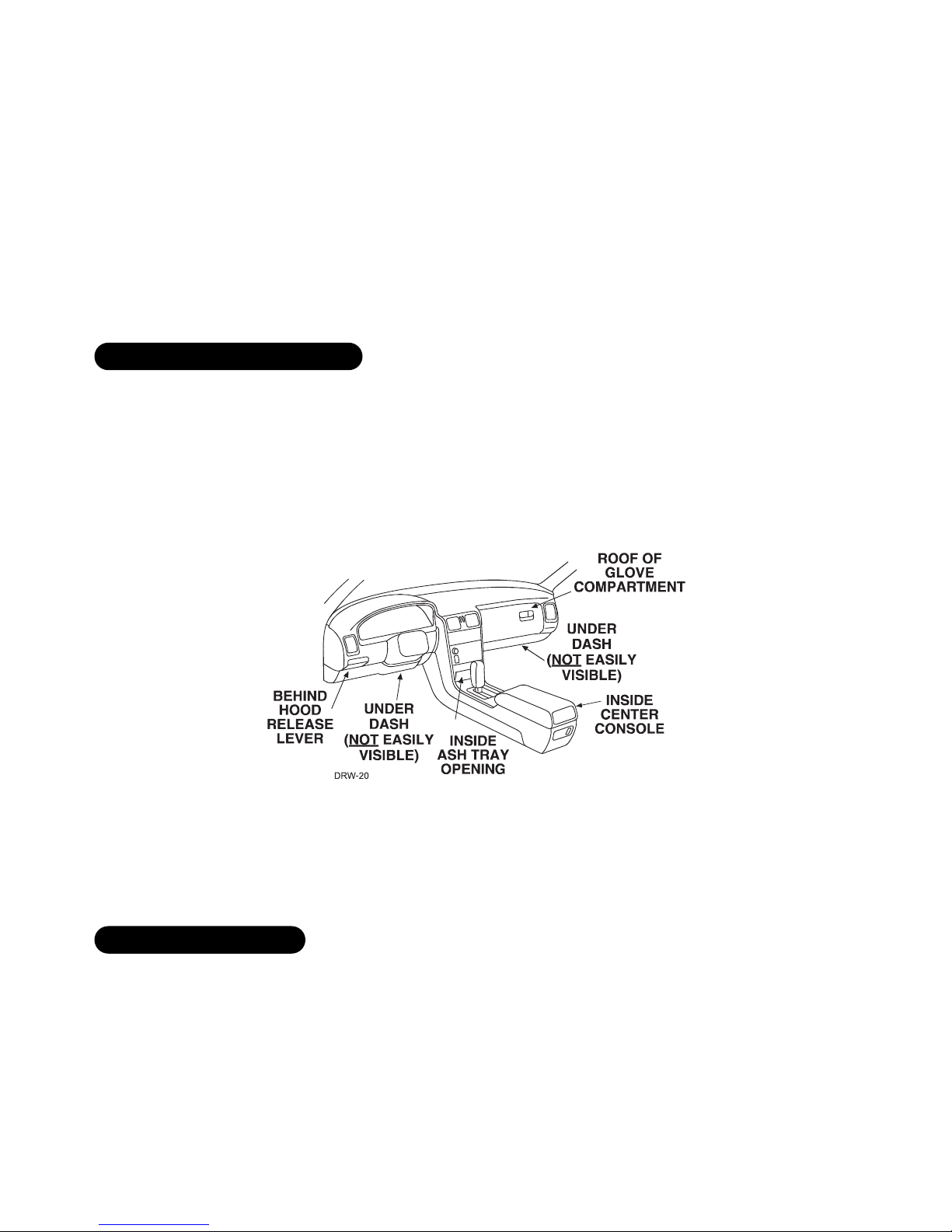
locations for the siren . . . . . . . . . . . . . . . . . . . . 6
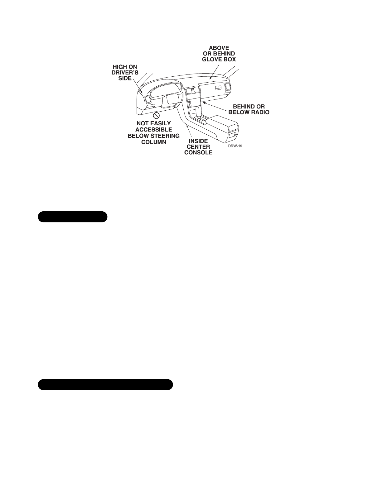
locations for the control module . . . . . . . . . . . . . 6
locations for stinger doubleguard shock sensor . . . 7
mounting the antenna . . . . . . . . . . . . . . . . . . . . 7
locations for valet/program switch . . . . . . . . . . . 8
locations for the status LED . . . . . . . . . . . . . . . . 8
locations for the optional starter kill relay . . . . . . 9
locations for the relay satellite . . . . . . . . . . . . . . 9
ffiinnddiinnggtthheewwiirreessyyoouunneeeedd........................................99
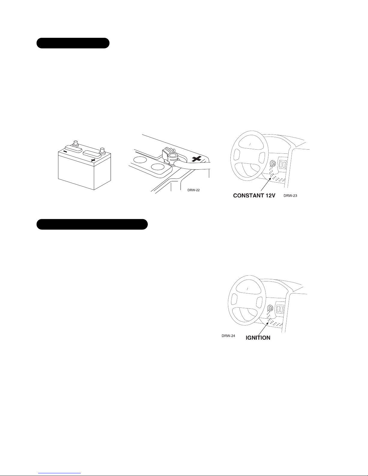
obtaining constant 12V . . . . . . . . . . . . . . . . . . 10
finding the 12V switched ignition wire . . . . . . . . 10
finding the starter wire . . . . . . . . . . . . . . . . . . 11
finding the accessory wire . . . . . . . . . . . . . . . . 11
finding the tachometer wire . . . . . . . . . . . . . . . 11
finding the wait-to-start bulb wire for diesels . . 12
finding a (+) parking light wire . . . . . . . . . . . . . 12
finding the door pin switch circuit. . . . . . . . . . . 13
mmaakkiinnggyyoouurrwwiirriinnggccoonnnneeccttiioonnss..............................1144
pprriimmaarryyhhaarrnneessss((HH11)),,1122--ppiinnccoonnnneeccttoorr....................1155
sseeccoonnddaarryyhhaarrnneessss((HH22)),,66--ppiinnccoonnnneeccttoorr..................1155
ddoooorrlloocckkhhaarrnneessss,,33--ppiinnccoonnnneeccttoorr..........................1166
rreemmootteessttaarrttpprriimmaarryyhhaarrnneessss,,77--ppiinnccoonnnneeccttoorr..........1166
hheeaavvyyggaauuggeerreellaayyssaatteelllliitteeccoonnnneeccttoorr......................1177
rreemmootteessttaarrttsseeccoonnddaarryyhhaarrnneessss((HH33)),,55--ppiinnccoonnnneeccttoorr..1177
hhoorrn
n,,cchhaannnneell66((HH44)),,22--ppiinnccoonnnneeccttoorr......................1177
pprriimmaarryyhhaarrnneessss((HH11))wwiirreeccoonnnneeccttiioonngguuiiddee..............1188
sseeccoonnddaarryyhhaarrnneessss((HH22))wwiirreeccoonnnneeccttiioonngguuiiddee..........2222
rreellaayyssaatteelllliitteeiiggnniittiioonns
swwiittcchhiinntteerrffaaccee........................
wwiirreeccoonnnneeccttiioonngguuiiddee......................................
......2244
heavy gauge wires . . . . . . . . . . . . . . . . . . . . . . 24
ribbon harness . . . . . . . . . . . . . . . . . . . . . . . . 25
auxiliary relay output harness . . . . . . . . . . . . . . 25
rreemmootteessttaarrttsseeccoonnddaarryyhhaarrnneessss((HH33))..........................
wwiirreeccoonnnneeccttiioonngguuiiddee............................................2266
hhoorrnn,,cchhaannnneell66hhaarrnneessss((HH44))....................................
wwiirreeccoonnnneeccttiioonngguuiiddee............................................2288
nneeuuttrraallssaaffeettyysswwiittcchhiin
ntteerrffaaccee................................2288
testing the neutral safety switch . . . . . . . . . . . . 29
bbyyppaassssiinnggGGMMvveehhiicclleeaannttii--tthheeffttssyysstteemmss((VVAATTSS))........3311
1
1999955aannddnneewweerrvveehhiicclleeaannttii--tthheeffttssyysstteemmss..................
((iimmmmoobbiilliizzeerrss))......................................................3322
passlock I and passlock II (PL-1 and PL-2) . . . . . 32
passkey III (PK-3), transponder-based systems . . 32
pplluugg--iinnLLEEDDaannddvvaalleett//pprrooggrraammsswwiittcchh......................3333
pprrooggrra
ammmmeerriinntteerrffaaccee,,33--ppiinnbbllaacckkpplluugg....................3333
sshhoocckksseennssoorrhhaarrnneessss,,44--ppiinnccoonnnneeccttoorr........
..............3344
ttaacchhlleeaarrnniinngg........................................................3355
pprrooggrraammmmiinnggjjuummppeerrss............................................3355
ttrraannssmmiitttteerr//rreecceeiivveerrlleeaarrnnrroouuttiinnee™™..........
................3366
tach threshold on/off . . . . . . . . . . . . . . . . . . . 36
light flash (+)/(-) . . . . . . . . . . . . . . . . . . . . . . 36
ttrraannssmmiitttteerrccoonnffiigguurraattiioonnss......................................3388
standard configuration . . . . . . . . . . . . . . . . . . . 38
ssyysstteemmffeeaat
tuurreesslleeaarrnnrroouuttiinnee..................................3399
ffeeaattuurreemmeennuuss................................
........................4422
menu #1 - basic features . . . . . . . . . . . . . . . . . 42
menu #2 - advanced features . . . . . . . . . . . . . . 43
menu #3 - remote start options. . . . . . . . . . . . . 44
ffeeaattuurreeddeessccrriippttiioonnss................................................4455
menu #1 - basic features . . . . . . . . . . . . . . . . . 45
menu #2 - advanced features . . . . . . . . . . . . . . 46
menu #3 - remote start options. . . . . . . . . . . . . 49
vvaalleettmmooddee............................................................5511
ttiimmeerrmmooddee............................................................5511
ttaabblleeooffzzoonneess........................................................5522
sshhuuttddoowwnnddiiaaggnnoossttiiccss............................................5522
to perform shutdown diagnostics . . . . . . . . . . . . 52
lloonnggtteerrmmeevveenntthhiissttoorryy..........................................5533
ssaaffeettyycchheecckk..........................................................5544
ttrroouubblleesshhoooottiinngg....................................................5555
alarm troubleshooting . . . . . . . . . . . . . . . . . . . 55
remote start troubleshooting. . . . . . . . . . . . . . . 55
wwiirriinnggqquuiicckkrreeffeerreenncceegguuiiddee....................................5577
rreellaayyssaatteelllliitteewwiirriinnggqquuiicckkrreef
feerreenncceegguuiiddee................5588

44© 2005 Directed Electronics—all rights reserved
wwhhaattiissiinncclluuddeedd
■The control module ■The plug-in status LED
■An XHF Plus receiver/antenna ■The plug-in Valet/Program switch
■One remote transceiver ■A 514N Neosiren
■One 4-button transmitter ■A hood pinswitch
■A Stinger Doubleguard shock sensor ■A toggle (override) switch
wwaarrnniinngg!!ssaaffeettyyffiirrsstt
The following safety warnings must be observed at all times:
■Due to the complexity of this system, installation of this product must only be performed by an authorized
Directed Electronics dealer.
■When properly installed, this system can start the vehicle via a command signal from the remote control
transmitter. Therefore, never operate the system in an area that does not have adequate ventilation. The fol-
lowing precautions are the sole responsibility of the user; however, authorized Directed Electronics dealers
should make the following recommendations to all users of this system:
1. Never operate the system in an enclosed or partially enclosed area without ventilation (such as a garage).
2. When parking in an enclosed or partially enclosed area or when having the vehicle serviced, the remote
start system must be disabled using the installed toggle switch.
3. It is the user's sole responsibility to properly handle and keep out of reach from children all remote
control transmitters to assure that the system does not unintentionally remote start the vehicle.
4. TTHHEEUUSSEERRMMUUSSTTIINNSSTTAALLLLAACCAARRBBOONNMMOONNOOXXIIDDEEDDEETTEECCTTOORRIINNOORRAABBOOUUTTTTHHEELLIIVVIINNGGAARREEAAAADDJJAACCEENNTTTTOO
T
THHEEVVEEHHIICCLLEE..AALLLLDDOOOORRSSLLEEAADDIINNGGFFRROOMMAADDJJAACCEENNTTLLIIVVIINNGGAARREEAASSTTOOTTHHEEEENNCCLLOOSSEEDDOORRPPAARRTTIIAALLLLYY
EENNCCLLOOSSEEDDVVEEHHIIC
CLLEESSTTOORRAAGGEEAARREEAAMMUUSSTTAATTAALLLLTTIIMMEESSRREEMMAAIINNCCLLOOSSEEDD..
■Use of this product in a manner contrary to its intended mode of operation may result in property damage,
personal injury, or death. Except when performing the Safety Check outlined in this installation guide, (1)
Never remotely start the vehicle with the vehicle in gear, and (2) Never remotely start the vehicle with the
keys in the ignition. The user will be responsible for having the neutral safety feature of the vehicle period-
ically checked, wherein the vehicle must not remotely start while the car is in gear. This testing should be
performed by an authorized Directed Electronics dealer in accordance with the Safety Check outlined in this
product installation guide. If the vehicle starts in gear, cease remote start operation immediately and consult
with the user to fix the problem immediately.
■After the remote start module has been installed, test the remote start module in accordance with the Safety

© 2005 Directed Electronics—all rights reserved 55
Check outlined in this installation guide. If the vehicle starts when performing the Neutral Safety Shutdown
Circuit test, the remote start unit has not been properly installed. The remote start module must be removed
or properly reinstalled so that the vehicle does not start in gear. All installations must be performed by an
authorized Directed Electronics dealer. OOPPEERRAATTIIOONNOOFFTTHHEERREEMMOOTTEESSTTAARRTTMMOODDUULLEEIIFFTTHHEEVVEEHHIICCLLEESSTTAARRTTSSIINN
GGEEAARRIISSCCOONNTTRRAARRYYTTOOIITTSSIINNTTEENNDDEEDDMMOOD
DEEOOFFOOPPEERRAATTIIOONN..OOPPEERRAATTIINNGGTTHHEERREEMMOOTTEESSTTAARRTTSSYYSSTTEEMMUUNNDDEERR
TTHHEESSEECCOONNDDIITTIIOONNSSMMAAYYRREESSUULLTTIINNPPRROOPPEERRTTYYDDAAMMA
AGGEEOORRPPEERRSSOONNAALLIINNJJUURRYY..IIMMMMEEDDIIAATTEELLYYCCEEAASSEETTHHEEUUSSEE
OOFFTTHHEEUUNNIITTAANNDDRREEPPAAIIRROORRDDIISSCCOONNNNEECCTTTTHHEEIINNSSTTAALLLLEEDD
RREEMMOOTTEESSTTAARRTTMMOODDUULLEE..DDIIRREECCTTEEDDEELLEECCTTRROONNIICCSS
WWIILLLLNNOOTTBBEEHHEELLDDRREESSPPOONNSSIIBBLLEEOORRPPAAYYFFOORRIINNSSTTAALLLLAATTIIOONNOORRRRE
EIINNSSTTAALLLLAATTIIOONNCCOOSSTTSS..
iinnssttaallllaattiioonnppooiinnttssttoorreemmeemmbbeerr
IIMMPPOORRTTAANNTT!!This product is designed for fuel-injected, automatic transmission vehicles only.
Installing it in a standard transmission vehicle is dangerous and is contrary to its intended use.
■Please read this entire installation guide before beginning the installation. The installation of this remote
start system requires interfacing with many of the vehicle’s systems. Many new vehicles use low-voltage or
multiplexed systems that can be damaged by low resistance testing devices, such as test lights and logic
probes (computer safe test lights). Test all circuits with a high quality digital multi-meter before making con-
nections.
■Do not disconnect the battery if the vehicle has an anti-theft-coded radio. If equipped with an air bag, avoid
disconnecting the battery if possible. Many airbag systems will display a diagnostic code through their
warning lights after they lose power. Disconnecting the battery requires this code to be erased, which can
require a trip to the dealer.
■Check with the customer on status LED location.
■Remove the domelight fuse. This prevents accidentally draining the battery.
■Roll down a window to avoid being locked out of the car.
■Test all functions. The “Using Your System” section of the Owner's Guide is very helpful when testing.
■When testing, don’t forget that this system is equipped with Nuisance Prevention Circuitry™(NPC™). NPC can
bypass trigger zones, making them appear to stop working. See the
Nuisance Prevention Circuitry
section.
■Review and complete the
Safety Check
section of this guide prior to the vehicle reassembly.
aafftteerrtthheeiinnssttaallllaattiioonn
bbeeffoorreebbeeggiinnnniinnggtthheeiinnssttaallllaattiioonn

66© 2005 Directed Electronics—all rights reserved
ddeecciiddiinnggoonnccoommppoonneennttllooccaattiioonnss
SSoommeetthhiinnggssttoorreemmeemmbbeerraabboouuttmmoouunnttiinnggtthheessiirreenn::
■Keep it away from heat sources, such as radiators, exhaust manifolds, turbochargers, and heat shields.
■Mount it where a thief cannot easily disconnect it, whether the hood is open or shut. Both the siren and its
wires should be difficult to find. This usually involves disguising the wire to look like a factory harness.
■We recommend against grounding the siren to its mounting screws. Instead, we recommend running both the
red and black wires into the passenger compartment and grounding to one common point for all devices.
After all, both wires are the same length and come already bonded together. Whenever possible, conceal your
wires in the factory harnesses or in the same style loom as the factory.
■When possible, place the siren on the same side of the vehicle as the control module, where its wires will
reach the control module’s wires without extending them. Always run the wires through the center of a
grommet, never through bare metal!
■Point the siren down so water does not collect in it.
SSoommeetthhiinnggssttoorreemmeemmbbeerraabboouuttwwhheerreetto
ommoouunntttthheeccoonnttrroollmmoodduullee::
■Never put the control module in the engine compartment!
■The first step in hot-wiring a vehicle is removing the driver's side under-dash panel to access the starter and
ignition wires. If the control module is placed just behind the driver's side dash it can easily be disconnected.
■When mounting the control module, try to find a secure location that will not require you to extend the har-
nesses’ wires (they are 1.5 meters long). Keep it away from the heater core (or any other heat sources) and
any obvious leaks.
llooccaattiioonnssffoorrtthheeccoonnttrroollmmoodduullee
llooccaattiioonnssffoorrtthheessiirreenn

© 2005 Directed Electronics—all rights reserved 77
Some good control module locations: above the glove box, inside the center console, above the under-dash fuse
box, above the radio, etc.
The antenna position should be discussed with the vehicle’s owner prior to installation, since the antenna may
be visible to the vehicle’s operator. The best location for the antenna is centered high on either the front or rear
windshield. For optimal range, the antenna should be mounted vertically. It can be mounted horizontally in rela-
tion to the windshield or under the dashboard away from metal, but range will be diminished. Metallic window
tint can also affect range, so this should be a consideration when determining the mounting location.
After determining the best mounting location, follow these steps:
1. Clean the mounting area with a quality glass cleaner or alcohol to remove any dirt or residue.
3. Mount the antenna using the supplied double-sided tape.
4. Route the antenna cable to the control module and plug it into the antenna connector.
IIMMPPOORRTTAANNTT!!To achieve the best possible range, DO NOT leave the antenna cable bundled under
the dash. Always extend the cable full length during installation, regardless of the antenna
mounting location.
SSoommeetthhiinnggssttoorreemmeemmbbeerraabboouuttwwhheerreettoommoouunntttthheesshhoocckksseennssoorr::
■Never put the Stinger®in the engine compartment!
■Find a spot close to the control module so that the wires do not need to be extended. Keep it away from the
heater core (or any other heat sources) and any obvious leaks.
llooccaattiioonnssffoorrssttiinnggeerrddoouubblleegguuaarrddsshhoocckksseennssoorr
mmoouunnttiinnggtthheeaanntteennnnaa

88© 2005 Directed Electronics—all rights reserved
HHoowwtthheeSSttiinnggeerr®®iissmmoouunntteeddiisstthheemmoossttiimmppoorrttaannttffaaccttoorriinniittssppeerrffoorrmmaannccee..WWeerreeccoommmmeennddttwwoommeetthhooddss::
■Using double-sided tape or hook-and-loop fastener to mount to a trim panel or an air duct, or
■Wire-tying to a wire harness.
If mounting the sensor where it cannot be easily reached for adjustment, hook-and-loop fastening tape (such as
Velcro) is recommended for ease of removal for future adjustments.
NNOOTTEE::In many vehicles, tying the sensor to a steering column or screwing it to metal will result
in poor sensitivity, especially at the rear of the vehicle.
IMPORTANT! When the vehicle is delivered, please show the user where this switch is located
and how to disarm the system with it.
Ensure that the location you pick for the switch has sufficient clearance to the rear. The switch should be well
hidden. It should be placed so passengers or stored items (such as in a glove box or center console) cannot acci-
dentally hit it. The switch fits into a 9/32-inch hole.
This system has Remote Valet. The user can enter and exit Valet Mode without having to reach the Valet/Program
switch. This feature was introduced so that switch location was less critical in day-to-day use. As long as the
Valet/Program switch can be reached to disarm without a transmitter, easy access is not important.
TThhiinnggssttoorreemmeemmbbeerrwwhheennppoossiittiioonniinnggtthheeSSttaattuussLLEEDD::
■It should be visible from both sides and the rear of the vehicle, if possible.
■It needs at least 1/2-inch clearance to the rear.
■It is easiest to remove a small panel, such as a switch blank or a dash bezel, before drilling a 9/32-inch hole.
■Use quick-disconnects near the LED wires if the panel is removable. This lets mechanics or other installers
remove the panel without cutting the wires.
llooccaattiioonnssffoorrtthheessttaattuussLLEEDD
llooccaattiioonnssffoorrvvaalleett//pprrooggrraammsswwiittcchh

© 2005 Directed Electronics—all rights reserved 99
If optional starter kill relay or its connections are immediately visible upon removal of the under-dash panel,
they can easily be bypassed. Always make the relay and its connections difficult to discern from the factory
wiring! Exposed yellow butt connectors do not look like factory parts, and will not fool anyone! For this reason,
routing the optional starter kill wires away from the steering column is recommended.
The relay satellite wiring carries large amounts of current. The wires should not be extended and should be cut
to the minimum length necessary. Since the relay satellite is functioning as the ignition switch in the vehicle,
it is often convenient to mount the relay satellite close to the main ignition switch harness.
ffiinnddiinnggtthheewwiirreessyyoouunneeeedd
Now that you have decided where each component will be located, you’re going to find the wires in the car that
the security system will be connected to.
IIMMPPOORRTTAANNTT!!Do not use a 12V test light or logic probe (computer safe test light) to find these
wires! Use a digital multimeter for all testing.
llooccaattiioonnssffoorrtthheerreellaayyssaatteelllliittee
llooccaattiioonnssffoorrtthheeooppttiioonnaallssttaarrtteerrkkiillllrreellaayy

1100© 2005 Directed Electronics—all rights reserved
We recommend two possible sources for 12V constant: the (+) terminal of the battery, or the constant supply to the
ignition switch. Always install a fuse within 12 inches of this connection. If the fuse also will be powering other
circuits, such as door locks, a power window module, a Nite-Lite® headlight control system, etc., fuse accordingly.
IIMMPPOORRTTAANNTT!!Do not remove the fuse holder on the red wire. It ensures that the control module
has its own fuse, of the proper value, regardless of how many accessories are added to the main
power feed.
The ignition wire is powered when the key is in the run or start position. This is because the ignition wire powers
the ignition system (spark plugs, coil) as well as the fuel delivery system (fuel pump, fuel injection computer).
Accessory wires lose power when the key is in the start position to make more current available to the starter motor.
HHoowwttooffiinndd((++))1122VViiggnniittiioonnwwiitthhyyoouurrmmuullttiimmeetteerr::
1. Set to DCV or DC voltage (12V or 20V is fine).
2. Attach the (-) probe of the meter to chassis ground.
3. Probe the wire you suspect of being the ignition wire. The
steering column harness or ignition switch harness is an excel-
lent place to find this wire.
4. Turn the ignition key switch to the run position. If your meter
reads (+)12V, go to the next step. If it doesn’t, probe another
wire.
5. Now turn the key to the start position. The meter display should stay steady, not dropping by more than a
few tenths of a volt. If it drops close to or all the way to zero, go back to Step 3. If it stays steady at (+)12V,
you have found an ignition wire.
ffiinnddiinnggtthhee1122VVsswwiittcchheeddiiggnniittiioonnwwiirree
oobbttaaiinniinnggccoonnssttaanntt1122VV

© 2005 Directed Electronics—all rights reserved 1111
The starter wire provides 12V directly to the starter or to a relay controlling the starter. In some vehicles, it is
necessary to power a cold start circuit. A cold start circuit will test exactly like a starter circuit, but it does not
control the starter. Instead, the cold start circuit is used to prime the fuel injection system for starting when the
vehicle is cold.
HHoowwttooffiinnddtthheessttaarrtteerrwwiirreewwiitthhyyoouurrmmuullttiimmeetteerr::
1. Set to DCV or DC voltage (12V or 20V is fine).
2. Attach the (-) probe of the meter to chassis ground.
3. Probe the wire you suspect of being the starter wire. The steering
column is an excellent place to find this wire. Remember you do not
need to interrupt the starter at the same point you test it. Hiding
your optional starter kill relay and connections is always recommended.
4. Turn the ignition key switch to the start position. Make sure the car
is not in gear! If your meter reads (+)12V, go to the next step. If it doesn’t, probe another wire.
5. Cut the wire you suspect of being the starter wire.
6. Attempt to start the car. If the starter engages, reconnect it and go back to Step 3. If the starter does not
turn over, you have the right wire.
An accessory wire will show +12V when the key is in the accessory and run positions. It will not show +12V during
the cranking cycle. There will often be more than one accessory wire in the ignition harness. The correct accessory
wire will power the vehicle's climate control system. Some vehicles may have separate wires for the blower motor and
the air conditioning compressor. In such cases, it will be necessary to add a relay to power the second accessory wire.
To test for a tachometer wire, a multimeter capable of testing AC voltage must be used. The tachometer wire will
show between 1V and 6V AC. In multi-coil ignition systems, the system can learn individual coil wires. Individual
coil wires in a multi-coil ignition system will register lower amounts of AC voltage. Also, if necessary, the system
can use a fuel injector control wire for engine speed sensing. Common locations for a tachometer wire are the
ignition coil itself, the back of the gauges, engine computers, and automatic transmission computers.
IIMMPPOORRTTAANNTT!!Do not test tachometer wires using a test light or logic probe (computer safe test light)!
This will damage the vehicle.
HHoowwttooffiinnddaattaacchhoommeetteerrwwiirreewwiitthhyyoouurrmmuullttiimmeetteerr::
1. Set to ACV or AC voltage (12V or 20V is fine).
2. Attach the (-) probe of the meter to chassis ground.
ffiinnddiinnggtthheettaacchhoommeetteerrwwiirree
ffiinnddiinnggtthheeaacccceessssoorryywwiirree
ffiinnddiinnggtthheessttaarrtteerrwwiirree

1122© 2005 Directed Electronics—all rights reserved
3. Start and run the vehicle.
4. Probe the wire you suspect of being the tachometer wire with the red probe of the meter.
5. If this is the correct wire the meter will read between 1V and 6V.
In diesel vehicles it is necessary to interface with the wire that turns on the WAIT TO START light in the dash-
board. This wire illuminates the bulb until the vehicle’s glow plugs are properly heated. When the light goes out
the vehicle can be started. This wire is always available at the connector leading to the bulb in the dashboard.
It can also be found at the Engine Control Module (ECM) in many vehicles.
TTootteessttaannddddeetteerrmmiinneetthheeppoollaarriittyyoofftthhiisswwiirree::
1. Set your multimeter to DCV or DC voltage (12 or 20V is fine).
2. Attach the (+) probe of the meter to (+)12V.
3. Probe the wire that you suspect leads to the bulb with the (-) probe of the meter.
4. Turn the ignition switch to the ON position.
5. If the meter indicates 12 volts until the light goes out you have isolated the correct wire and the wire's polar-
ity is negative (ground while the bulb is on).
6. If the meter reads zero volts until the light goes out and then reads 12 volts, you have isolated the correct
wire and the wire's polarity is positive.
The (+) parking light wire is often found near the switch. Many cars have the switch built into the turn signal
lever, and in these cars the parking light wire can be found in the steering column. The same wire is often avail-
able in the kick panel or running board.
NNOOTTEE::Many Toyotas, as well as many other Asian vehicles, send a (-) signal from the switch to
a relay. The relay then sends (+)12V to the bulbs. Whenever you have difficulty finding a (+)
parking light wire near the switch, simply test the wires at any switch or control panel which is
lit by the instrument panel lighting. Remember, you need a (+) parking light wire that does not
vary with the dimmer setting.
HHoowwttooffiinnddaa((++))ppaarrkkiinngglliigghhttffllaasshhwwiirreewwiitthhyyoouurrmmuullttiimmeetteerr::
1. Set to DCV or DC voltage (12V or 20V is fine).
2. Attach the (-) probe of the meter to chassis ground.
3. Probe the wire you suspect of being the parking light wire. Usually, the area near the headlight/parking light
switch is an excellent area to start, as is the kick panel.
4. Turn on the parking lights. If your meter shows (+)12V, turn off the parking lights and make sure it goes back
to zero.
5. If it does return to zero, turn the parking lights back on and, using the dash light dimmer control, turn the
ffiinnddiinnggaa((++))ppaarrkkiinngglliigghhttwwiirree
ffiinnddiinnggtthheewwaaiitt--ttoo--ssttaarrttbbuullbbwwiirreeffoorrddiieesseellss

© 2005 Directed Electronics—all rights reserved 1133
brightness of the dash lights up and down. If the meter changes more than a volt when using the dimmer,
look for another wire. If it stays relatively close to (+)12V, you have found your parking light wire.
TThheebbeessttppllaacceessttooffiinnddtthheeddoooorrsswwiittcchhwwiirreeaarree::
■At the pin switch: When testing at the pin switch, check the wire to ensure that it “sees” all the doors. Often,
the passenger switch will cover all the doors even if the driver’s switch will not.
■At the dome light: This may not be your best choice if the vehicle has delayed domelight supervision, but it
will work in many Hondas, or any vehicle with completely diode-isolated pin switches.
Once you have determined the wire color, the easiest place to connect to the wire is often at the kick panel, at
the windshield pillar, or in the running board. When an easy location is not available, running a wire to the dome-
light itself is often the best solution.
HHoowwttooffiinnddaaddoooorrppiinnsswwiittcchhttrriiggggeerrwwi
irreewwiitthhyyoouurrmmuullttiimmeetteerr::
1. Set to DCV or DC voltage (12V or 20V is fine).
2. In most Fords, fasten the (-) probe of the meter to chassis ground. In most other cars, fasten the (+) probe
of your meter to (+)12V constant.
3. Probe the wire you suspect of being the door trigger wire. If the meter reads (+)12V when any door
is opened, you have found a trigger wire.
NNOOTTEE::Make sure the wire you use “sees” all the doors! Some newer GM vehicles lack standard-
type pin switches. The dome light in these vehicles is turned on when the door handle is lifted.
These usually have a blue/white or white wire coming out of the door into the kick panel which
will provide a (-) trigger for all doors. Some GM vehicles (some Cavaliers, Grand Ams, etc.) have
a yellow wire coming out of the door which provides a (+) door trigger.
ffiinnddiinnggtthheeddoooorrppiinnsswwiittcchhcciirrccuuiitt

1144© 2005 Directed Electronics—all rights reserved
mmaakkiinnggyyoouurrwwiirriinnggccoonnnneeccttiioonnss
Before making your connections, plan how your wires will be routed through the vehicle. For instance, the red
12V constant input and the orange ground-when-armed output (for the optional starter kill relay) will often be
routed together to the ignition switch harness. In order to keep the wiring neat and make it harder to find, you
may wish to wrap these wires together in electrical tape or conceal them in tubing similar to what the manu-
facturer used.
There are two acceptable ways of making a wire connection - solder connections and crimp connectors. When
properly performed, either type of connection is reliable and trouble-free. Regardless of whether you solder your
connections or you use mechanical-type crimp-on connections, ensure that all connections are mechanically
sound and that they are insulated.
Cheap electrical tape, especially when poorly applied, is not a reliable insulator. It often falls off in hot weather.
Use good-quality electrical tape or heat shrink.
■Never twist-and-tape the wires together without soldering.
■Never use “fuse taps”, as they can damage fuse box terminals.
If you use tapping connectors such as 3M T-Taps (not to be confused with Scotch-Locks), avoid using them in
higher-current applications (constant 12V, ground, etc.). Some tapping connectors are inferior in quality and
should be avoided.

© 2005 Directed Electronics—all rights reserved 1155
pprriimmaarryyhhaarrnneessss((HH11)),,1122--ppiinnccoonnnneeccttoorr
______
______
______
______
______
______
______
______
______
______
______
______
sseeccoonnddaarryyhhaarrnneessss((HH22)),,66--ppiinnccoonnnneeccttoorr
______
______
______
______
______
______ LLIIGGHHTTBBLLUUEE((--))SSEECCOONNDDUUNNLLOOCCKKOOUUTTPPUUTT
WWHHIITTEE//BBLLAACCKK((--))CCHHAANNNNEELL55OOUUTTPPUUTT
VVIIOOLLEETT//BBLLAACCKK((--))CCHHAANNNNEELL44OOUUTTPPUUTT
GGRREEEENN//WWHHIITTEE((--))FFAACCTTOORRYYAALLAARRMMRREEAARRMM
GGRRAAYY//BBLLAACCKK((--))WWAAIITTTTOOSSTTAARRTT
LLIIGGHHTTGGRREEEENN//BBLLAACCKK((--))FFAACCTTOORRYYDDIISSAARRMM
HH22//11
HH22//22
HH22//33
HH22//44
HH22//55
HH22//66
RREEDD//WWHHIITTEE((--))220000mmAACCHHAANNNNEELL22VVAALLIIDDIITTYYOOUUTTPPUUTT
RREEDD((++))CCOONNSSTTAANNTTPPOOWWEERRIINNPPUUTT
BBRROOWWNN((++))SSIIRREENNOOUUTTPPUUTT
EEMMPPTTYYNNOOTTUUSSEEDD
BBLLAACCKK((--))CCHHAASSSSIISSGGRROOUUNNDDIINNPPUUTT
VVIIOOLLEETT((++))DDOOOORRTTRRIIGGGGEERRIINNPPUUTT,,ZZOONNEE33
BBLLUUEE((--))TTRRUUNNKKIINNPPUUTT,,ZZOONNEE11
GGRREEEENN((--))DDOOOORRTTRRIIGGGGEERRIINNPPUUTT,,ZZOONNEE33
BBLLAACCKK//WWHHIITTEE((--))220000mmAADDOOMMEELLIIGGHHTTSSUUPPEERRVVIISSIIOONNOOUUTTPPUUTT
WWHHIITTEE//BBLLUUEE((--))RREEMMOOTTEESSTTAARRTTAACCTTIIVVAATTIIOONNIINNPPUUTT
WWHHIITTEE((++))//((--))SSEELLEECCTTAABBLLEELLIIGGHHTTFFLLAASSHHOOUUTTPPUUTT
OORRAANNGGEE((--))550000mmAAAARRMMEEDDOOUUTTPPUUTT
HH11//11
HH11//22
HH11//33
HH11//44
HH11//55
HH11//66
HH11//77
HH11//88
HH11//99
HH11//1100
HH11//1111
HH11//1122

1166© 2005 Directed Electronics—all rights reserved
ddoooorrlloocckkhhaarrnneessss,,33--ppiinnccoonnnneeccttoorr
______
______
______
rreemmootteessttaarrttpprriimmaarryyhhaarrnneessss,,77--ppiinnccoonnnneeccttoorr
______
______
______
______
______
______
______ BBLLUUEE((--))220000mmAASSTTAATTUUSSOOUUTTPPUUTT
OORRAANNGGEE//BBLLAACCKK((--))AANNTTIIGGRRIINNDD//GGRROOUUNNDDWWHHEENNAARRMMEEDDOOUUTTPPUUTT
PPUURRPPLLEE((--))220000mmAASSTTAARRTTEERRRREELLAAYYTTUURRNN--OONN
OORRAANNGGEE((--))220000mmAAAACCCCEESSSSOORRYYRREELLAAYYTTUURRNN--OONN
PPIINNKK((--))220000mmAAIIGGNNIITTIIOONNRREELLAAYYTTUURRNN--OONN
YYEELLLLOOWW((++))IIGGNNIITTIIOONNIINNPPUUTTTTOOAALLAARRMM
PPIINNKK//WWHHIITTEE220000mmAA((--))PPRROOGGRRAAMMMMAABBLLEEIIGGNN22//AACCCC22RREELLAAYYTTUURRNNOONN
11
22
33
44
55
66
77
BBLLUUEE((++))LLOOCCKK((--))UUNNLLOOCCKKOOUUTTPPUUTT
EEMMPPTTYYNNOOTTUUSSEEDD
GGRREEEENN((--))LLOOCCKK((++))UUNNLLOOCCKKOOUUTTPPUUTT
11
22
33

© 2005 Directed Electronics—all rights reserved 1177
hheeaavvyyggaauuggeerreellaayyssaatteelllliitteeccoonnnneeccttoorr
______
______
______
______
______
______
______
______
rreemmootteessttaarrttsseeccoonnddaarryyhhaarrnneessss((HH33)),,
55--ppiinnccoonnnneeccttoorr
______
______
______
______
______
hhoorrnn,,cchhaannnneell66((HH44)),,22--ppiinnccoonnnneeccttoorr
______
______ BBRROOWWNN((--))220000mmAAHHOORRNN
OORRAANNGGEE//BBLLAACCKKCCHHAANNNNEELL66OOUUTTPPUUTT
HH44//11
HH44//22
BBLLAACCKK//WWHHIITTEE((--))NNEEUUTTRRAALLSSAAFFEETTYYSSWWIITTCCHHIINNPPUUTT
VVIIOOLLEETT//WWHHIITTEETTAACCHHOOMMEETTEERRIINNPPUUTTWWIIRREE
BBRROOWWNN((++))BBRRAAKKEESSHHUUTTDDOOWWNNWWIIRREE
GGRRAAYY((--))HHOOOODDPPIINNSSWWIITTCCHHIINNPPUUTT,,ZZOONNEE11
BBLLUUEE//WWHHIITTEE((--))220000mmAA22NNDDSSTTAATTUUSS//RREEAARRDDEEFFOOGGGGEERR--LLAATTCCHHEEDD//PPUULLSSEEDD
HH33//11
HH33//22
HH33//33
HH33//44
HH33//55
RREEDD//WWHHIITTEE((++))HHIIGGHHCCUURRRREENNTT1122VVIINNPPUUTT
PPIINNKK//WWHHIITTEE((++))OOUUTTPPUUTTTTOOSSEECCOONNDDIIGGNNIITTIIOONNCCIIRRCCUUIITT
RREEDD((++))HHIIGGHHCCUURRRREENNTT1122VVIINNPPUUTT
PPIINNKK((++))OOUUTTPPUUTTTTOOPPRRIIMMAARRYYIIGGNNIITTIIOONNCCIIRRCCUUIITT
OORRAANNGGEE((++))OOUUTTPPUUTTTTOOAACCCCEESSSSOORRYYCCIIRRCCUUIITT
RREEDD((++))HHIIGGHHCCUURRRREENNTT1122VVIINNPPUUTT
GGRREEEENNOONNBBOOAARRDDSSTTAARRTTEERRKKIILLLL((KKEEYYSSIIDDEE))
PPUURRPPLLEE((++))OOUUTTPPUUTTTTOOSSTTAARRTTEERRCCIIRRCCUUIITT((SSTTAARRTTEERRSSIIDDEE))
11
22
33
44
55
66
77
88

1188© 2005 Directed Electronics—all rights reserved
pprriimmaarryyhhaarrnneessss((HH11))wwiirreeccoonnnneeccttiioonngguuiiddee
This wire supplies a (-)500 mA ground as long as the system is armed. This output ceases as soon as the system
is disarmed. The orange wire may be wired to an optional Directed Electronics 8618 starter kill relay.
As shipped, this wire should be connected to the (+) parking light wire. If the light flash polarity jumper under
the sliding door is moved to the opposite position (see
Internal Programming Jumper
section of this guide), this
wire supplies a (-) 200 mA output. This is suitable for driving (-) light control wires in Toyota, Lexus, BMW, some
Mitsubishi, some Mazda, and other model cars.
((++))PPoossiittiivveeLLiigghhttFFllaasshhOOuuttppuutt
((--))LLiigghhttFFllaasshhOOuuttppuutt
NNOOTTEE::For parking light circuits that draw 10 amps or more, the internal jumper must be switched
to a (-) light flash output. (See the Internal Programming Jumper section of this guide.) PP//NN
88661177or a standard automotive SPDT relay must be used on the H1/2 light flash output harness
wire.
HH11//22WWHHIITTEE((++//--))sseelleeccttaabblleelliigghhttffllaasshhoouuttppuutt
HH11//11OORRAANNGGEE((--))ggrroouunndd--wwhheenn--aarrmmeeddoouuttppuutt

© 2005 Directed Electronics—all rights reserved 1199
This input comes from the factory set to 2 activation pulses. This means that it is necessary to have 2 consecu-
tive ground pulses on the white/blue wire for the remote start to activate or to deactivate. The same holds true
for the remote control activation when set to a two pulse setting it is necessary to press the button twice
for the remote start to activate or deactivate.
NNOOTTEE::When the activation pulse count has been programmed to 1 or 2 pulses it will affect both
activation inputs; the White/Blue wire and the remote control activation.
Connect this wire to the optional domelight supervision relay as shown below:
IIMMPPOORRTTAANNTT!!This output is only intended to drive a relay. It cannot be connected directly to the
domelight circuit, as the output cannot support the current draw of one or more light bulbs.
Most vehicles use negative door trigger circuits. Connect the green wire to a wire which shows ground when any
door is opened. In vehicles with factory delays on the domelight circuit, there is usually a wire that is unaffected
by the delay circuitry. This wire will report Zone 3.
HH11//55GGRREEEENN((--))ddoooorrttrriiggggeerriinnppuutt,,zzoonnee33
HH11//44BBLLAACCKK//WWHHIITTEE((--))220000mmAAddoommeelliigghhttssuuppeerrvviissiioonnoouuttppuutt
HH11//33WWHHIITTEE//BBLLUUEErreemmootteessttaarrtt((--))aaccttiivvaattiioonniinnppuutt

2200© 2005 Directed Electronics—all rights reserved
This wire is connected to the trunk pinswitch. If the trunk is open while the system is armed, this input will
trigger the security system This wire will report Zone 1.
This wire is used in vehicles that have a positive (+) switched dome light circuit. Connect the violet wire to a
wire that shows (+)12V when any door is opened, and ground when the door is closed. This wire will report Zone 3.
Connect this wire to a clean, paint-free sheet metal location (driver kick panel) using a factory bolt that DOES
NOT have any vehicle component grounds attached to it. A screw should only be used when in conjunction with
a two-sided lock washer. Under dash brackets and door sheet metal are not acceptable ground points. It is rec-
ommended that all remote start/security components be grounded at the same location.
HH11//88BBLLAACCKK((--))cchhaassssiissggrroouunnddccoonnnneeccttiioonn
HH11//77VVIIOOLLEETT((++))ddoooorrttrriiggggeerriinnppuutt,,zzoonnee33
HH11//66BBLLUUEE((--))ttrruunnkkiinnppuutt,,zzoonnee11
Table of contents
Other Viper Car Alarm manuals
Popular Car Alarm manuals by other brands

Volvo
Volvo 440 Directions for use

jablotron
jablotron CA-2103 Athos user manual

Freedom
Freedom Freedom 411atv Owner's manual & wiring instructions

Clifford
Clifford 980074 SERIES 11CX user guide

Python
Python 700 owner's guide

Omega Research & Development
Omega Research & Development INSTALLATION MANUAL installation manual

Soundoff Signal
Soundoff Signal INTERSECTOR ENT2B Series quick start guide

Toyota
Toyota vss3 Settings guide

Authorized Alarms
Authorized Alarms Controur operating manual

MEGATRONIX
MEGATRONIX MEGALARM MEGA 2700 installation manual

Directed Electronics
Directed Electronics Valet 561T installation guide

Crime Guard
Crime Guard 750i6 Operation manual