Viper 500+ User manual

Table of Contents
Experienced security installers may skip to Pg. 8, but read
all the italicized sections, as they describe changes and/or new features.
Installation Points to Remember Page 2
Deciding on Component Location 3
Finding the Wires you Need 5
Step-by-step meter instructions!
Making your Wire Connections 7
Primary Harness Diagram 8
Wire Connection Guide 9
Plug in LED and Valet®/Program Switch 11
Four-pin Shock Sensor Harness 11
New Multiplex Inputs
Bypassing Sensor Inputs 12
Door Lock Wiring Diagrams 12-15
Transmitter/Receiver Learn Routine™16
Two-vehicle Operation with Single Transmitter 17
Operating-Settings Learn Routine™
18
Feature Descriptions 20
Nuisance Prevention®Circuitry 21
Valet®Mode 21
Table of Zones 22
Vehicle Recovery System(VRS®) Installation 22
Troubleshooting 23
INSTALLATION
GUIDE
Directed Electronics, Inc.
VVIIPPEERR
500+
®

© 1995,1997 Directed Electronics, Inc. Vista, CA 297N437.597
Do not disconnect the battery if the vehicle has an antitheft-coded radio. If equipped with an air bag, avoid
disconnecting the battery if possible. IMPORTANT: Many airbag systems will display a diagnostic code through
their warning light after they lose power. Disconnecting the battery requires this code to be erased, a procedure
that can require a trip to the dealer.
Before beginning the installation:
•Check with the customer on Status LED location.
•Remove the domelight fuse. This prevents accidentally draining the battery.
•Roll down a window to avoid being locked out of the car.
After the install:
•Test all functions. The "Using Your System" section of the Owner's Guide is very helpful when testing.
•When testing, don’t forget that this system is equipped with Nuisance Prevention®Circuitry.
NPC™ can bypass trigger zones, making them appear to stop working. (See page 21)
INSTALLATION POINTS TO REMEMBER
Pre-wired 8618
Starter Kill
Relay
Plug-in
Valet
®
/Program
switch
Primary
Harness
H1
3-pin
2-wire
door
lock
harness
Two 491T
remote
transmitters
Plug-in
Status LED
VRS
®
plug-in
switch
Removable door
for programming
jumpers
504T Plug-in
Stinger™ shock
sensor
514T
Revenger™
Soft-chirp™
siren
2-pin
mini
red
VRS
®
plug
2-pin
mini
blue
Valet
®
/
Program
plug
4-pin
504T
shock
sensor
plug
2-pin
micro
LED
plug

© 1995,1997 Directed Electronics, Inc. Vista, CA 397N437.597
Step One:
Deciding on Component Locations
Siren
Some things to remember when mounting the siren:
•Keep it away from heat sources. Radiators, exhaust manifolds, turbochargers, and heat shields are all
things to avoid.
•Mount it where a thief cannot easily disconnect it, whether the hood is open or shut. Both the siren and
its wires should be difficult to find. This usually involves disguising the wire to look like a factory harness.
•We recommend against grounding the siren to its
mounting screws. Instead, we recommend running
both the red and black wires into the passenger
compartmentandgroundingtoonecommonpointfor
all devices. After all, both wires are the same length
and come already bonded together. Whenever
possible,concealyour wiresin thefactoryharnesses
or in the same style loom as the factory.
•When possible, put the siren on the same side of the
vehicle as the control module, where its wires will
reach the control module’s wires without extending
them. Always run the wires through the center of a
grommet, never through bare metal!
•Point the siren down so water does not collect in it.
Control Module
Never put the control module in the engine compartment!
The first step in hot-wiring a vehicle is removing the driver's side underdash panel to access the starter and ignition
wires. If the control module is placed just behind the driver's side dash it can easily be disconnected.
Whenlocating thecontrol module,try tofind asecurelocationthatwill notrequire youto extendthe harnesses’ wires
(theyare1.5meterslong).Keepitawayfromtheheatercore(orany
other heat sources) and any obvious leaks.
The higher the control module is in the vehicle, the better the
transmitterrangewill be. Ifyouput the controlmoduleunder a seat
or inside a metal dashboard, range will suffer, and you may wish to
add a 542T Range Extending Antenna (available separately).
Somegoodcontrolmodulelocations:Abovetheglovebox,insidethe
center console, above the underdash fuse box, above the radio, etc.

© 1995,1997 Directed Electronics, Inc. Vista, CA 497N437.597
Stinger
®
Doubleguard
®
Shock Sensor
Never put the Stinger®in the engine compartment!
Find a spot close to the control module so that the wires do not need to be extended. Keep it away from the heater
core (or any other heat sources) and any obvious leaks.
How the Stinger is mounted is the most important factor in its performance. We recommend two mounting methods:
Using double-sided tape or hook-and-loop fastener to mount to a trim panel or an air duct, or wire-tying to a wire
harness.Ifmountingthesensorwhereitcannotbeeasilyreachedforadjustment,hook-and-loopfasteningtape(such
as Velcro) is recommended for ease of removal for future adjustments.
NOTE: In many vehicles, tying the sensor to a steering column or screwing it to metal will result in poor
sensitivity, especially on the rear of the vehicle.
Valet
®
Program Switch
Ensure that the location you pick for the switch has sufficient clearance to the rear. The switch should be well hidden.
It should be placed so passengers or stored items (such as in a glove box or center console) cannot accidentally hit
it. The switch fits in a 9/32" hole.
Thissystemhas Remote Valet®.The usercanenter and exitValet®Modewithouthaving to reachthe Valet®/program
switch. DEI®introduced this feature so that switch location was less critical in day-to-day use. As long as the
Valet®/program switch can be reached to disarm without a transmitter, easy access is not important.
IMPORTANT! When the vehicle is delivered, please show the user where the switches are located and
how to disarm the system with it.
Status LED
Things to remember when positioning the Status LED:
•Itshouldbevisiblefrombothsidesandtherearofthevehicle,ifposible.
•It needs at least 1/2" clearance to the rear.
•It is easiest to use a small removable panel, such as a switch blank or
a dash bezel. Remove it before drilling your 9/32" hole.
•Use quick-disconnects near the LED wires if the panel is removable.
Thislets mechanicsor otherinstallers removethe panelwithout cutting
the wires.

© 1995,1997 Directed Electronics, Inc. Vista, CA 597N437.597
Optional Starter Kill Relay
If Starter Kill Relay or its connections are immediately visible upon removal of the underdash panel, they can easily
be bypassed. Always make the relay and its connections difficult to discern from the factory wiring! Exposed yellow
butt connectors do not look like factory parts, and will not fool anyone! For this reason, routing the starter kill wires
away from the steering column is recommended.
Step 2:
Finding the Wires You Need
Now that you have decided where each component will be located, you’re going to find the wires in the car that the
security system will be connected to.
IMPORTANT! Donotuse a12V testlightto findthese wires!Alltesting describedin thismanualis described
using a digital multimeter
.
Obtaining Constant 12V
We recommend two possible sources for 12V constant: The (+) terminal of the battery, or the constant supply to the
ignition switch.
Always install a fuse within 12 inches of this connection. If the fuse also will be powering other
circuits, such as door locks, a power window module, a Nite-Lite®headlight control system, etc.; fuse accordingly.
IMPORTANT! Do not remove the fuse holder on the red wire. It ensures that the control module has its own
fuse, of the proper value, regardless of how many accessories are added to the main power feed.
Finding the 12V Switched Ignition Wire
The ignition wire is powered when the key is in the run or start position. This is because the ignition wire powers the
ignition system (spark plugs, coil) as well as the fuel delivery system (fuel pump, fuel injection computer). Accessory
wires,onthe other hand,losepower when thekey is in thestart position tomakemore current availabletothe starter
motor.
How to find (+)12V ignition with your multimeter:
1. Set to DCV or DC voltage (12V or 20V is fine).
2. Attach the (-) probe of the meter to chassis ground.
3. Probe the wire you suspect of being the ignition wire. The steering column
harness or ignition switch harness is an excellent place to find this wire.
4. Turn theignition key switchtothe runposition.If your meterreads (+)12V,
go to the next step. If it doesn’t, probe another wire.
5. Nowturnthekeytothestartposition.Themeterdisplayshouldstaysteady,
not dropping by more than a few tenths of a volt. If it drops close to or all
the way to zero, go back to step 3. If it stays steady at (+)12V, you have
found an ignition wire.

© 1995,1997 Directed Electronics, Inc. Vista, CA 697N437.597
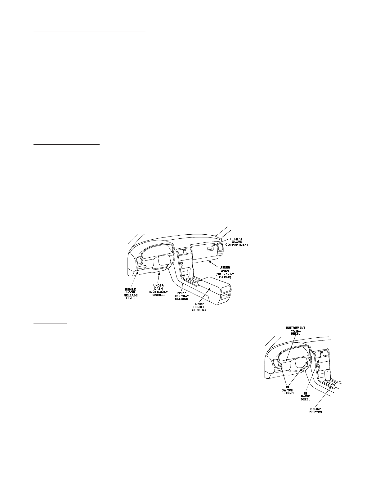
Finding a (+) Parking Iight Wire
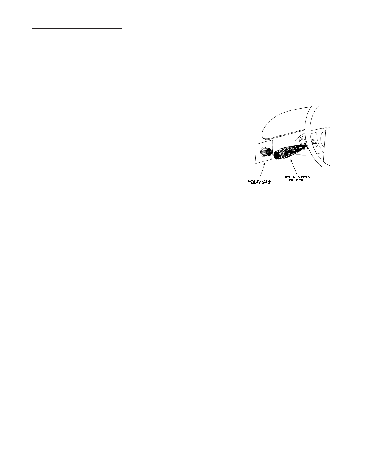
The(+)parking light wireis often foundnearthe switch. Manycars have theswitchbuilt into theturn signal lever,and
in these cars the parking light wire can be found in the steering column. The same wire is often available in the kick
panel or running board.
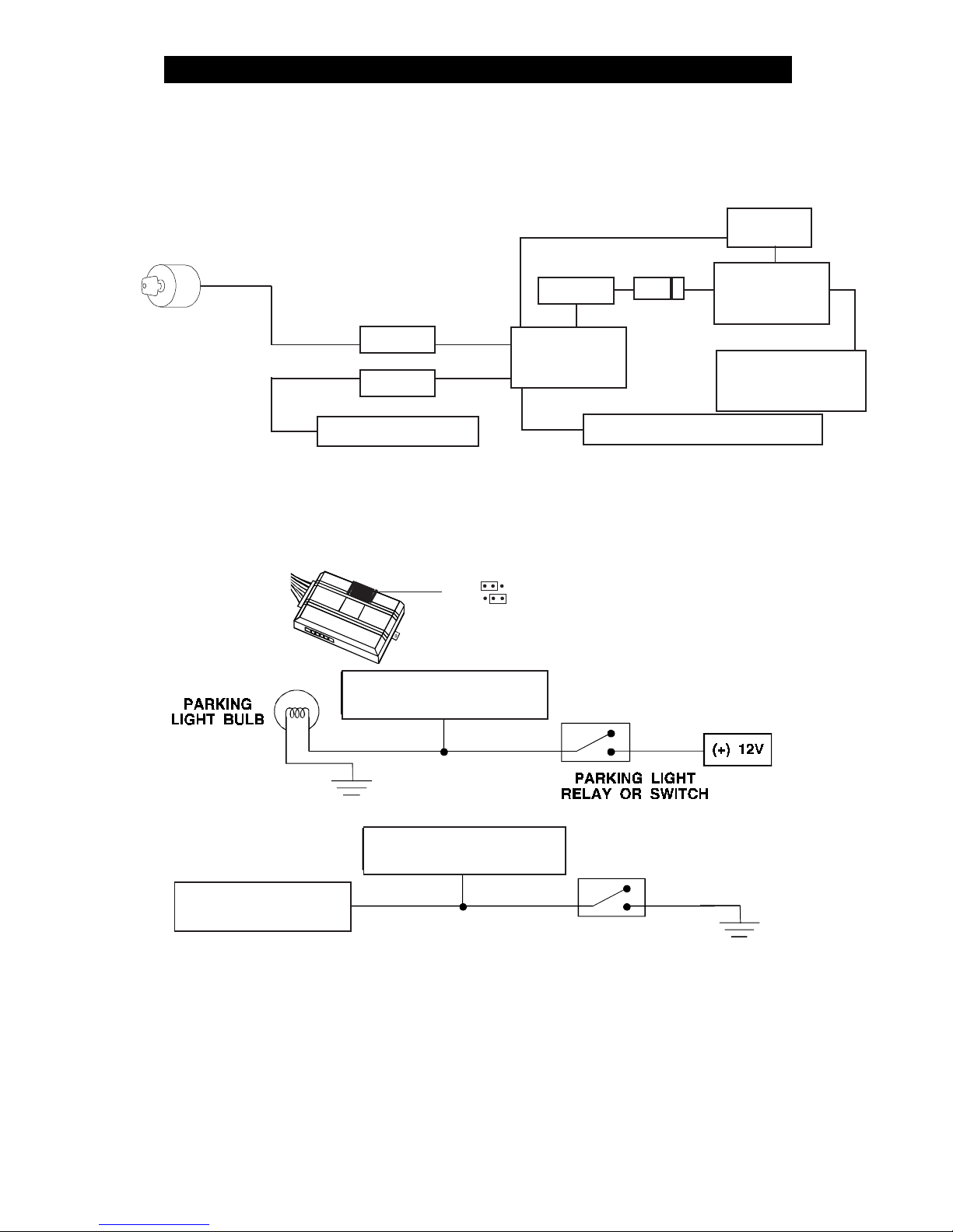
NOTE: Many Toyotas, as well as many other Asian vehicles, send a (-) signal from the switch to a relay. The
relay then sends 12V(+) to the bulbs. Whenever you have difficulty finding a (+) parking light wire near the
switch, simply test the wires at any switch or control panel
which is lit by the instrument panel lighting.
Remember, you need a (+) parking light wire that does not vary with dimmer setting.
How to find a (+) parking light flash wire with your multimeter
1. Set to DCV or DC voltage (12V or 20V is fine).
2. Attach the (-) probe of the meter to chassis ground.
3. Probe the wire you suspect of being the parking light wire. Usually,
the area near the headlight/parking light switch is an excellent area
to start, as is the kick panel.
4. Turn on the parking lights. If your meter shows (+)12V, turn off the
parking lights and make sure it goes back to zero.
5. If it does return to zero, turn the parking lights back on and, using the dash light dimmer control, turn the
brightness of the dash lights up and down.
If the meter changes more than a volt when using the dimmer,
look for another wire.
If it stays relatively close to (+)12V, you have found your parking light wire.
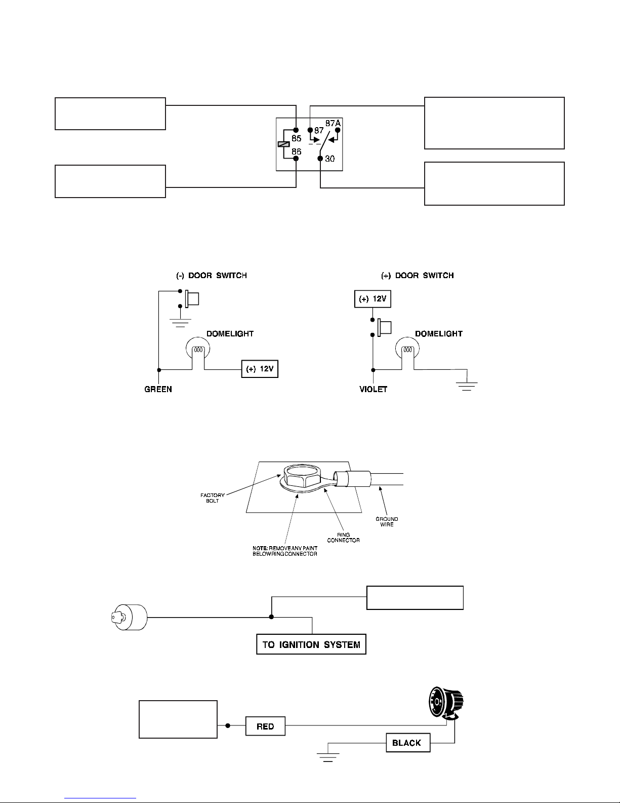
Finding the Door Pin Switch Circuit
The best places to find the door switch wire are:
At the pin switch
:
When testing at the pin switch, check the wire to ensure that it “sees” all the doors. Often,
the passenger switch will cover all the doors even if the driver’s switch will not.
At the dome light
:
This may not be your best choice if the vehicle has delayed domelight supervision, but
it will work in many Hondas, or any vehicle with completely diode-isolated pin switches.
Once you have determined the wire color, the easiest place to connect to the wire is often at the kick panel, at the
windshieldpillar,or intherunning board. Whenan easy locationis not available,running a wireto the domelightitself
is often the best solution.
How to find a door pin switch trigger wire with your multimeter:
1. Set to DCV or DC voltage (12V or 20V is fine).
2. InmostFords,fastenthe(-)probeofthemetertochassisground.Inmostothercars,fastenthe(+)probe
of your meter to (+)12V constant.
3. Probe the wire you suspect of being the door trigger wire. If the meter reads (+)12V when any door is
opened, you have found a trigger wire.
NOTE: Make sure the wire you use “sees” all the doors! Some newer GM vehicles lack standard-type
pinswitches. Thedomelightinthesevehiclesis turned onwhen thedoorhandleislifted. Theseusually
have a blue/white or white coming out of the door into the kick panel which will provide a (-) trigger for
all doors. Some GM vehicles (some Cavaliers, Grand Ams, etc.) have a yellow wire coming out of the
door which provides a (+) door trigger.

© 1995,1997 Directed Electronics, Inc. Vista, CA 797N437.597
How to find the (+)12V starter wire with your multimeter:
1. Set to DCV or DC voltage (12V or 20V is fine).
2. Attach the (-) probe of the meter to chassis ground.
3. Probe the wire you suspect of being the starter wire. The steering
column is an excellent place to find this wire. Remember you do not
need to interrupt the starter at the same point you test it. Hiding your
starter kill relay and connections is always recommended.
4. Turntheignition keyswitchto thestartposition.Make sure the car is
not in gear! If your meter reads (+)12V, go to the next step. If it
doesn’t, probe another wire.
5. Cut the wire you suspect of being the starter wire.
6. Attempt to start the car. If the starter engages, reconnect it and go back to step 3. If the starter does not
turn over, you have the right wire.
Step 3:
Making Your Wire Connections
Before making your connections, plan how your wires will be routed through the vehicle. For instance, the yellow
ignitioninput,thered12Vconstantinput,andtheorangeground-when-armedoutput(fortheoptionalstarterkillrelay)
will often be routed together to the ignition switch harness. In order to keep the wiring neat and make it harder to find,
youmaywishtowrapthesewirestogetherinelectricaltapeorconcealthemintubingsimilartowhatthemanufacturer
used.
Therearetwoacceptablewaysofmakingawireconnection:Solderconnectionsandcrimp connectors.Whenproperly
performed, either type of connection is reliable and trouble-free. Regardless of whether you solder your connections
or you use mechanical-type crimp-on connections, ensure that all connections are mechanically sound and that they
are insulated.
Cheap electrical tape, especially when poorly applied, is not a reliable insulator. It often falls off in hot weather. Use
good-quality electrical tape or heat shrink.
Never
twist-and-tape the wires together without soldering.
Never
use “fuse taps,” as they can damage fuse box terminals.
Ifyouusetappingconnectors suchas3M T-Taps(notto beconfusedwithScotch-Locks),avoidusingthemin higher-
current applications (constant 12V, ground, etc.). Some tapping connectors are inferior in quality and should be
avoided.

© 1995,1997 Directed Electronics, Inc. Vista, CA 897N437.597
PRIMARY HARNESS DIAGRAM H1, 12-PIN CONNECTOR
ORANGE (-) 500 MA ARMED OUTPUT
WHITE (+) (-) SELECTABLE LIGHT FLASH OUTPUT
WHITE/BLUE (-) 200 MA CHANNEL 3 VALIDITY OUTPUT
BLACK/WHITE (-) 200 MA DOMELIGHT SUPERVISION OUTPUT
GREEN (-) DOOR TRIGGER INPUT, ZONE 3
BLUE (-) INSTANT TRIGGER INPUT, ZONE 1
VIOLET (+) DOOR TRIGGER INPUT, ZONE 3
BLACK (-) CHASSIS GROUND INPUT
YELLOW (+) SWITCHED IGNITION INPUT, ZONE 5
BROWN (+) SIREN OUTPUT
RED (+) CONSTANT POWER INPUT
RED/WHITE (-) 200 MA CHANNEL 2 VALIDITY OUTPUT
H1/1
H1/2
H1/3
H1/4
H1/5
H1/6
H1/7
H1/8
H1/9
H1/10
H1/11
H1/12

© 1995,1997 Directed Electronics, Inc. Vista, CA 997N437.597
H1/1ORANGE
(-)ground-when-armedoutput:Thiswiresuppliesa(-)500mAgroundaslongasthesystemisarmed.
This output ceases as soon as the system is disarmed. The orange wire is pre-wired to control the 8618 starter kill
relay. NOTE:IfconnectingtheORANGEwiretocontrolanothermodule,suchasa529Tor530Twindowcontroller,
a 1 amp diode (type 1N4004) will be required. Insert the diode as shown below.
H1/2WHITE
lightflash output:As shipped,this wireshouldbeconnectedto the(+) parkinglight wire.If thelight flash
polarity jumper under the sliding door is moved to the opposite position (see below), this wire supplies a (-) 200 mA
output. This is suitable for driving (-) light control wires in Toyota, Lexus, BMW, some Mitsubishi, some Mazda, etc.
H1/3 WHITE/BLUE
channel 3 (-) output: This wire provides a (-) 200 mA signal whenever the transmitter code
controllingchannel3isreceived.Thissignalwillcontinueaslongasthattransmissionisreceived.Useforoptionssuch
as the 551T Valet® Start system, the 529T or 530T power window controllers, etc.
IMPORTANT!Neverusethiswiretodriveanythingbutarelayoralow-currentinput!Thetransistorizedoutput
canonlyprovide200 mAof current,and connectingdirectlytoasolenoid,motor,orotherhigh-currentdevice
will cause it to fail.
WIRE CONNECTION GUIDE
LEARN VALET
LIGHT(-) LIGHT (+)
PARKING LIGHT
SWITCH
WHITE H1/2
(-) LIGHT FLASH OUTPUT
FACTORY PARKING
LIGHT RELAY
WHITE H1/2
(+) LIGHT FLASH OUTPUT
BLACK
GREEN
TO STARTER MOTOR
X
X
ORANGE
IGNITION SWITCH 1N4004DIODE
PRE-WIRED
STARTER KILL
RELAY
ORANGE (-)
WHEN-ARMED
OUTPUT
TO OPTIONAL
SENSORS, 529T,
530T, ETC.
CONTROL
UNIT
IMPORTANT! Never interrupt any wire other than the starter wire. cccc
(+) YELLOW SWITCHED IGNITION
YELLOW

© 1995,1997 Directed Electronics, Inc. Vista, CA 10 97N437.597
H1/4BLACK/WHITE
(-)200mA
domelight-supervisionoutput:Connectthiswiretotheoptionaldomelightsupervision
relay as shown below:
IMPORTANT: This output is only intended to drive a relay. It cannot be connected directly to the domelight
circuit, as the output cannot support the current draw of one or more light bulbs.
H1/5 GREEN
(-) door trigger
or
H1/7 VIOLET
(+)
door trigger input: If the door switch wire you found is (-) when the
door is open, connect the GREEN wire to it. If the door switch wire you found is (+) when the door is open, use the
VIOLET wire instead.
IMPORTANT! Test to make sure this wire "sees" all doors!
H1/6BLUE
(-) instant trigger: This input will respond to a (-)input with an instant trigger. It is ideal for hood and trunk
pins and will report on zone one.
H1/8BLACK
(-)chassis groundconnection. Connectthis wireto baremetal,preferablywithafactorybolt ratherthan
your own screw (screws tend to either strip or loosen with time). We recommend grounding all your components to
the same point in the vehicle.
H1/9 YELLOW
(+) ignition input. Connect this wire to an ignition wire as described on page 5. This wire must show
+12V with the key in run position and during cranking. Take great care that this wire cannot be shorted to the chassis
at any point.
H1/10 BROWN
(+) siren output: Connect this to the red wire of the 514T Revenger™ siren. Connect the black wire
of the siren to (-) chassis ground, preferably at the same point you grounded the control module’s H1/8 BLACK wire.
H1/4 BLACK/WHITE
(+) 12V
CONSTANT FUSED
(-) CHASSIS GROUND IF
DOORS ARE (-) SWITCHED,
(+) 12V IF DOORS ARE
(+) SWITCHED
H1/5 GREEN (-) DOOR INPUT
OR
H1/7 VIOLET (+) DOOR INPUT
BROWN H1/10
(+) 12V SIREN
OUTPUT
YELLOW H1/9
PRIMARY HARNESS

© 1995,1997 Directed Electronics, Inc. Vista, CA 11 97N437.597
H1/11RED
(+)12Vconstantpowerinput:Beforeconnectingthiswire,removethesuppliedfuse.Connect tothebattery
positive terminal or the constant 12V supply to the ignition switch as described on Page 5.
NOTE: Always use a fuse within 12 inches of the point you obtain (+)12V. Do not use the 10A fuse in the
harness for this purpose. This fuse protects the module itself.
H1/12RED/WHITE
channel 2, 200mA (-) output: When the system receives the code controlling channel, for longer
than 1.5 seconds, the red/white will supply an output as long as the transmission continues. This is often used to
operate a trunk/hatch release or other relay-driven function.
IMPORTANT!Neverusethiswiretodriveanythingbutarelayoralow-currentinput!Thetransistorizedoutput
can only supply 200 mA of current, connecting directly to a solenoid, motor, or other high-current device will
cause it to fail.
(+) 12V CONSTANT FUSED
RED/WHITE H1/1
FUNCTION 2 OUTPUT
(+)12V IF (+) SWITCHED
(-) GROUND IF (-) SWITCHED
SWITCHED TRUNK RELEASE WIRE
87
87A
85
86
30
RED/WHITE H1/12
CHANNEL 2 OUTPUT
PLUG-IN LED AND VALET®/ PROGRAM SWITCH
These plug into the module. The Status LED plugs into the small two-pin socket, while the Valet® /Program Switch
should be plugged into the larger blue two-pin connector. The Status LED fits in a 9/32" hole.
Status LED Valet®/Program Switch
GREEN
(-) Multiplex input: Inputs shorter than .8 seconds will trigger the Warn Away®response, while inputs longer
than.8seconds willtriggerfull alarm sequenceand report zonefour. If installinganoptional DEI®dual stagesensor,
connecttotheGREENwireasshownbelow.Thediagrambeloweliminatestheneedfordiodestoisolatethesensors,
as well as providing a seperate zone for each sensor.
Diagram for adding optional DEI
®
dual stage sensor to GREEN wire (zone 4)
BLUE
(-)Multiplexinput:Inputsshorterthan.8secondswilltriggertheWarnAway®response,whileinputslongerthan
.8 seconds will trigger full alarm sequence and report zone two.
RED, BLACK
: RED is (+)12V constant, BLACK is (-) ground. Do not use these for anything besides the plug in
shock sensor.
FOUR-PIN SHOCK SENSOR HARNESS
xx
CUT
BLUE WIRE OF PRE-
WIRED PLUG
GREEN WIRE OF PRE-
WIRED PLUG
BLUE WIRE FROM PLUG-
IN SHOCK SENSOR
GREEN WIRE FROM
PLUG-IN SHOCK SENSOR
BLUE AND GREEN WIRES
FROM DEI®DUAL STAGE
SENSOR

© 1995,1997 Directed Electronics, Inc. Vista, CA 12 97N437.597
HARNESS 2, (+/-) DOOR LOCK OUTPUTS
This system can control two common power door lock types without any additional parts! With certain vehicles, or if
an actuator is to be installed, either a 451M Door Lock Relay Satellite or two relays will be required.
IMPORTANT! If you mistake a Type C direct-wired system for a Type A positive-pulse system, the module
will be damaged!
Type A - (+) 12V Pulses From the Switch to the Factory Relays
The system can control this type of system directly, with no additional parts. The switch will have three wires on it,
and one will test (+)12V constantly. The others will alternately pulse (+)12V when the switch is pressed to the lock or
unlock position.
If you cannot get to the switch, and you find a set of wires that pulse (+)12V alternately on lock and unlock, you must
take care to ensure that it is not a Type C direct-wire system.
Here is a test: Cut the wire which pulses (+)12V on lock, and then operate the switch to unlock.
If all doors unlock, the vehicle uses Type A system.
If you lose all door lock operation in both directions, you are operating the master switch in a Type C system.
If you lose all door lock operation of one or more, but not all motors stop operating, and other doors still work, you
have cut a wire leading directly to one or more motors. You must instead find the actual wires leading to the switch.
BYPASSING SENSOR INPUTS
There are times when you need to temporarily bypass all sensor inputs to the unit, such as when remote starting the
vehicle. Anytimeanauxiliarychanneloutputisused,allinputsarebypassedfor5seconds. Duringthe5secondbypass
period, ground can be supplied to the H1/6BLUE wire without triggering the unit. When the 5 second bypass period
ends,iftheunitseesgroundontheH1/6BLUEwire,alltriggerinputsexceptthedoortriggerinputwillremainbypassed
until5secondsaftergroundisremovedfromthebluewire. Thiscanbedoneusingthestatusoutputofa551Tremote
start unit as shown below:
551T REMOTE
START UNIT BLUE (-) STATUS
OUTPUT
TO OPTIONAL HOOD/
TRUNK PINS OR SENSORS BLUE WIRE H1/6,
ZONE 1 INPUT CONTROL UNIT
IN4004
DIODE
GREEN (-) LOCK, (+) UNLOCK OUTPUT
EMPTY UNLESS USING 451M
BLUE (-) UNLOCK, (+) LOCK OUTPUT
H2/A
H2/B
H2/C

© 1995,1997 Directed Electronics, Inc. Vista, CA 13 97N437.597
Many domestically-made GM vehicles use Type A locks. However, many more GM vehicles are now Type C than in
previous years. The full-size pickups (1989-up), many of the S10 Blazers, the Corvette, '95 Cavalier/Sunfire 1993 -
and newer, Camaro/Firebird all use Type C door locks, and cannot be controlled without a 451M! Almost all
domestically-built Fords are Type C. Ford builds almost no Type A systems. Chrysler builds both Type A and Type
C, so use care.
H2/C BLUE (+) LOCK OUTPUT
H2/A GREEN (+) UNLOCK OUTPUT
FACTORY
RELAYS
(+)12 V
LOCK UNLOCK
POWER
DOOR LOCK
SWITCH
Type B
- (-) Pulses From the Switch to the Factory Relays
This system is common in many Toyota, Nissan, Honda, Saturn, as well as Ford models with a factory keyless-
entry system (some other Fords also use Type B).
Theswitchwill havethree wiresonit, andonewire willtest groundallthe time.One wire willpulse (-)whenthe switch
locks the doors, and the other wire will pulse (-) when the switch unlocks the doors. This type of system is difficult to
mistake for any other type.
H2/A GREEN (-) LOCK OUTPUT
H2/C BLUE (-) UNLOCK OUTPUT
FACTORY
RELAYS
GROUND
POWER
DOOR LOCK
SWITCH
LOCK UNLOCK
IMPORTANT! Remember that functions of these wires reverse between Type A and Type B!

© 1995,1997 Directed Electronics, Inc. Vista, CA 14 97N437.597
Type C - Reversing Polarity
Interfacing with a reversing polarity system requires either two relays or one 451M (not included).
It is critical to identify the proper wires and locate the master switch to interface properly. Locate wires that show
voltage on lock and unlock. Cut one of the suspect wires and check operation of the locks from both switches. If
one switch loses operation in both directions and the other switch operates in one direction only, you have located
one of the target wires. The switch that lost all operation is the master switch. If one switch works both directions
and the other switch works only one direction, you have a Type A system. If both switches still operate, but one
or more doors have stopped responding entirely, you have cut a motor lead. Reconnect it and continue to test for
another wire. Once both wires have been located and the master switch identified, cut both wires and interface as
shown below.
Important! If these are not connected properly, you will send (+) 12 volts directly to (-) ground, possibly
damaging the alarm or the factory switch.
Type D - Aftermarket Actuators
In order for this system to control one or more aftermarket actuators, a 451M or two relays (optional) are needed.
Vehicles without factory power door locks require the installation of one actuator per door. This requires mounting
the door lock actuator inside the door. Other vehicles may only require one actuator installed in the driver's door if
all door locks are operated when the driver's lock is used. This type of installation is required to operate factory
lock systems in Volvo (except 850), SAAB, and most Mazda, Isuzu and Subaru models.
The fuse used on 12 volt inputs should be 7.5A per motor installed in the vehicle.
IMPORTANT! Do not connect the outputs of the alarm directly to the actuator!

© 1995,1997 Directed Electronics, Inc. Vista, CA 15 97N437.597
Type E - Mercedes-Benz and Audi (1985 & Newer)
Door locks are controlled by an electrically activated vacuum pump. Some Mercedes and Audis use a Type D
system. Test by locking doors from the passenger key cylinder. If all the doors lock, the vehicle's door lock
system can be controlled with just two relays (optional). The control wire can be found in either kick panel and will
show (+)12V when doors are unlocked and (-) ground when doors are locked.
To interface see diagram below. The system must be programmed for 3.5 second door lock pulses (see
Opera-
tion-Settings Learn Routine
™
).
Type F - One-Wire System
This system usually requires a negative pulse to unlock, and cutting the wire to lock the door. In some vehicles,
these are reversed. It is found in late-model Nissan Sentras, some Nissan 240SX, and Nissan 300ZX 1992-up. It
is also found in some Mazda MPV and Mitsubishi models.
One relay (optional) is used to interface to this type of system as follows:

© 1995,1997 Directed Electronics, Inc. Vista, CA 16 97N437.597
TRANSMITTER/RECEIVER LEARN ROUTINE™
In order to enter Learn Routine™ the Valet® /Program button must be plugged into the blue port. There is a basic
sequence to remember whenever programming this unit: Door, Key, Choose, Transmit and Release.
1. Door Openadoor.EithertheH1/5GREEN ortheH1/7VIOLETdoor
trigger wire must be connected for the control unit to “see” an
open door.
2. Key Turn the ignition on to the run position. The H1/9 YELLOW
switched ignition input must be connected.
3. Choose Within15seconds, pressand releasethe momentarybutton
to select the channel you wish to program:
Press and Release To Program
One time Arm/disarm/panic
Two times Channel two output
(Silent Mode™/Remote Valet® )
Three times Channel three output
NOTE: When programming a transmitter button to step three, the assigned button will provide an
instant output on the red/white wire.
Onceyou haveselectedthestep,press thebutton oncemoreandholdit. The unitwillchirpone,two
or three times depending on the channel selected. Do not release the momentary button.
4. Transmit While holding the momentary button, press the button on the transmitter that
you would like to control the selected receiver channel. One chirp will confirm
that the code has been learned.
5. Release Once the code is learned, the button can be released.
You can step from one step to another by releasing the Valet®/program button and tapping it to advance steps
and then holding it. For instance: You have programmed channel one and you want to program channel two.
Release the Valet®/program button. Press it one time and release it to advance from step one to step two. Now,
press and hold the button down and the unit will chirp twice. As before, do not release it.
If you want to program channel two (instant) after programming channel one, release the momentary button press it
twice and release it to advance to step three. Then press it once more and hold it. The siren will chirp three times to
confirm it is ready to receive the code from the transmitter.
Learn Routine™ will be exited if:
• Ignition is turned off
• Door is closed
• Program button is pressed too many times
• More than 15 seconds elapses between steps
One long chirp indicates that Learn Routine™has been exited

© 1995,1997 Directed Electronics, Inc. Vista, CA 17 97N437.597
TWO-VEHICLE OPERATION WITH SINGLE TRANSMITTER
You can get two-vehicle operation with the transmitters that come with the system. However, you cannot use
all the auxiliary channels of the system (or all the auxiliary channels of the other system), unless using a
485T 4-button
transmitter.
Here's what to do:
1. Using Learn Routine™, program Button I into system # 1 as the arm/disarm button. Do this with all
four remotes.
2. Do the same with system # 2, except program Button II of all four remotes as the arm/disarm button.
If using DEI
®
485T four-button remotes,
all auxiliary channels are available on both vehicles. Before program-
ming, make a list of all channels on each vehicle, and decide which button(s) should control which channel.
For example, if you wanted the top two buttons to control vehicle # 1 and the bottom two buttons to control
vehicle # 2, here is how each system would be programmed:
Vehicle # 1:
Button I = arm/disarm.
Button II = trunk release/Silent Mode™.
Button I+II = channel three.
Vehicle # 2:
Button III = arm/disarm.
Button IV = trunk/release/Silent Mode™.
Button III+IV = channel three.

© 1995,1997 Directed Electronics, Inc. Vista, CA 18 97N437.597
OPERATING-SETTINGS LEARN ROUTINE™
Many of the operating settings of this unit are programmable. They can be changed whenever necessary through a
computer-basedLearnRoutine™.TheValet®
/programpush-buttonswitch,pluggedintotheblueportisusedtogether
with a programmed transmitter to change the settings. To program settings remember: Door, Key, Choose, Transmit
and Release.
1. Door Open a door. Either the H1/5
GREEN
or the H1/7
VIOLET
door
trigger wire must be connected for the control unit to “see” an
open door.
2. Key Turn the ignition on and then back off. The H1/9 YELLOW
switched ignition input must be connected.
3. Choose Within 15 seconds, press and release the Valet®/Program
button the number of times corresponding to the number of
the desired feature (see the chart below). The one chirp
settings below are the factory default settings, except where
indicated by bold text.
Feature Number One-chirp Setting Two-chirp Setting
1 Active arming Passive arming
2 Arm/disarm chirps on Arm/disarm chirps off
3 Ignition-controlled door locks Standard door locks
4 Active locking only Passive locking
5 Panic with ignition on No panic with ignition on
6 0.8 second door lock pulses 3.5 second door lock pulses
7 Forced passive arming on Forced passive arming off
8 Automatic engine disable on Automatic engine disable off
9 VRS®enabled VRS®disabled
10 Code-Hopping™ on Code-Hopping™ off
11 Siren Horn honk

© 1995,1997 Directed Electronics, Inc. Vista, CA 19 97N437.597
Once the button has been pressed and released the correct number of times press it once more and hold it. After
asecond,thesirenwillchirptoindicatewhatstepyouhaveaccessed. Forexample,threechirpswouldindicateaccess
to the ignition controlled door lock feature.
4. Transmit While holding the Valet® /program button, use the arm/disarm
button of the transmitter, to toggle between the one and two chirp
settings. The one-chirp settings are the factory defaults.
5. Release The button can now be released.
For example, to program the arming mode from active to passive, press and release the Valet/program button once.
Then press and hold it. The siren will chirp once, indicating that the setting can now be changed. While holding the
Valet/programbutton,pressthearm/disarmbuttononthetransmitter. Thesirenwillchirptwicetoindicatethatpassive
arminghasbeenprogrammed.Ifthisisthedesiredsetting,releasetheValet/programbutton. Ifthisis notthedesired
setting,continuetoholdtheValet/programbuttonandpressthearm/disarmbuttononthetransmitteragain. Thesiren
will chirp once indicating that active arming has been programmed. Once the desired setting has been selected,
release the Valet/program button.
YoucanadvancefromsteptostepbypressingandreleasingtheValet/programbuttonthenumberoftimesnecessary
to get from the step you just programmed to the step you wish to access. If you just programmed the arm/disarm
chirps to off and you want to program passive locks, release the Valet/program button, press and release it twice to
step from feature two to feature four. Then press it once more and hold it. The unit will chirp four times to confirm that
you have accessed feature number four.
The Learn Routine™ will be exited if:
• The ignition is turned on.
• The door is closed.
• The Valet® button is pressed too many times.
• More than 15 seconds elapses between steps.
The siren will emit a long chirp when Learn Routine™ is exited.

© 1995,1997 Directed Electronics, Inc. Vista, CA 20 97N437.597
1 – ACTIVE/PASSIVE ARMING:
Whenactive armingisselected,thesystem willonly armwhen thetransmitter isused.
Whensettopassive,thesystemwillarmautomatically30secondsafterthelastdoorisclosed.Passivearmingisindicated
by the rapid flashing of the LED when the last protected entry point is closed.
2 – ARM/DISARM CHIRPS ON/OFF:
This feature controls the chirps that confirm the arming and disarming of the
system.
3 – IGNITION CONTROLLED DOOR LOCKS ON/OFF:
When turned on, the doors will lock three seconds after the
ignition is turned on and unlock when the ignition is turned off. The doors will not lock if the ignition is turned on with the
door open.
4–ACTIVE/PASSIVELOCKING:
Ifpassivearmingisselectedinstepone,thenthesystemcanbeprogrammedtoeither
lock the doors when passive arming occurs, or only lock the doors when the system is armed via the transmitter. Active
locking means the system will not lock the doors when it passively arms. Passive locking means that the system will lock
the doors when it passively arms.
5 PANIC WITH IGNITION ON:
This step controls whether or not the panic mode is available with the ignition on. In
some states, there are laws prohibiting a siren sounding in a moving vehicle. This feature makes the system compliant
with these regulations.
6 DOORLOCKPULSEDURATION:
SomeEuropeanvehicles,suchasMercedes-BenzandAudi,requirelongerlock
andunlockpulsestooperatethevacuumpump.Programmingthesystemtoprovide3.5secondpulses,willaccommodate
door lock interface in these vehicles. The default setting is .8 second door lock pulses.
See "Mercedes-Benz and Audi
- 1985 and Newer (Type E)"
diagram on page 15.
7 – FORCED PASSIVE ARMING ON/OFF:
To use this feature, passive arming must be selected in step one. When
turnedon,forcedpassivearmingwillensurethatthesystemwillpassivelyarm,evenifazoneisleftopenorinvalid.Forced
passive arming occurs one hour after the ignition is turned off.
8–AUTOMATICENGINEDISABLE(AED)ON/OFF:
AEDisafulltime,passivestarterdisablethatworksindependently
of the security system. If AED is desired, the optional Starter Kill Relay must be installed. When turned on, the H1/1
ORANGE, ground when armed output will go active 30 seconds after the ignition is turned off. The LED will flash at half
its normal rate when the ignition is turned off to indicate that AED is on and will interrupt the starter in 30 seconds. AED
does not occur in Valet® Mode and can be bypassed using the emergency override procedure. The transmitter can be
used to disarm AED, however, the system would have to be armed and then disarmed when using the transmitter.
9 –VEHICLE RECOVERY SYSTEM (VRS
®
) ENABLED/DISABLED:
This feature is used to tell the system whether
or not the VRS® button has been installed. As shipped, the VRS® is disabled. If installing the VRS® button, you will
need to enable the VRS®.
10–CODE-HOPPING™ON/OFF:
Thesystemusesamathematicalformulatochangeitscodeeachtimethetransmitter
and receiver communicate. This makes the group of bits or "word" from the transmitter very long. The longer the word
is, the easier it is to block its transmission to the unit. Disabling the Code-Hopping™feature lets the receiver ignore the
Code-Hopping™part of the transmitter word. As a result, the unit may have better range with Code-Hopping™off.
11 – SIREN/HORN HONK:
The system can be programmed to output pulses instead of a continuous output when the
system is triggered. This is useful to honk the factory horn in applications where a siren is undesirable. Remember that
theunitisonly capableofsupplying 1ampoffcurrent.Arelaywillbe requiredtointerface withmostfactoryhornsystems.
FEATURE DESCRIPTIONS
Table of contents
Other Viper Car Alarm manuals

Viper
Viper 500 ESP User manual

Viper
Viper 4104 User manual

Viper
Viper SmartStart 5000 Series User manual

Viper
Viper 5906V User manual

Viper
Viper 3100 User manual

Viper
Viper 4606V User manual

Viper
Viper Car Alarm 420 ESP User manual

Viper
Viper 791 XV User manual

Viper
Viper 106V User manual

Viper
Viper 791 XV User manual
Popular Car Alarm manuals by other brands

Cobra
Cobra 8185 User instructions

Audiovox
Audiovox APS996A - Prestige Remote Security System installation manual

Clifford
Clifford AvantGuard 3 owner's guide

Clifford
Clifford AvantGuard 5.1 installation guide

Crime Guard
Crime Guard Crime Guard 533i4 Operation manual

Silencer Security Systems
Silencer Security Systems 4901 owner's manual